Madell QK857D Installation guide

1
MADELL QK857D
DOUBLE VORTEX SOFT BLOWER HOT AIR REWORK STATION
OPERATION and MAINTENANCE MANUAL
1,Summary of product
1-1,Specifications
MODEL
857D
TYPE
ITEM Digital display CPU controlled temperature
Power consumption 580W
Air pump DC Motor, double vortex blower
Air volume 100 l/min(Max)
Temperature range 100℃--450℃
Display Digital display(resolution 1℃)
Length of handle
assembly 110cm
Noise <78dB

2
1-2.Features
1.Closed loop sensor feedback, temperature is controlled by zero
voltage triggering mode and is not affected by air volume. Powerful, rapid
heating up, accurate and stable.
2.Wide range of hot air volume adjustment.
3.Electromagnetic inductor switch inside the handle starts the hot air when
the handle is picked up. The rework station is set to an idle mode when the
handle is placed back to the holder.
4.Increased heating element life and safety with built in automatic cooling
feature.
5.Compact design, occupy less space.
1-3.Applications
1.Suitable for soldering and desoldering various SMD components, such as
SOIC,QFP,PLCC,BGA chips.
2.Can also be used for heat shrinkage, paint and sticker removal, preheating,
sterilizing, glue connecting etc.
2.Installation and Operation
2-1.Handle holder assembling
1.Install and tighten the four screws as shown in the diagram as per your
personal habits.
2.Remove the two screws which fix the handle holder on the left or right
side of the unit.
3.Align the two holes of handle holder to the two corresponding holes on
the unit, tighten the removed two screws.
4.Place the handle assembly on the handle holder and check the condition
carefully.

3
2-2.Operational guide
1.Place the handle on the holder.
2.Plug the power cord into the power socket of the unit.
3.Supply power to the rework station.
4.Select and mount appropriate nozzle.
5.Set power switch to ”I”position, the unit will start working.
6.Set temperature as needed.
7.Pick up the handle, the unit should start working immediately. Set
appropriate air volume and start your work when temperature remains
stable.
8.Hot air gun must be put back on the holder whenever not used. Meanwhile,
the hot air will be cut off and cold air starts to cool the heating element
automatically. The unit will be in idle status with temperature below 100
℃.
9.Disconnect the power cord when not in use for a long time.
* Try to use lower temperature and large hot air volume. Doing so will
increase heating element life and ensure the safety of IC’s.
3.Temeperature Setting
1.The set temperature will be displayed while the temperature knob is turned.
2.Clockwise turn of the temperature knob will raise the temperature while
counterclockwise lowers it. Actual temperature or “---“will be displayed
and the unit enters standby mode after the set temperature displays for two
seconds.
Note:
1. “---”implies temperature at air outlet is below 100℃.When the handle
is on the holder, the unit is in standby mode.
2. “S-E”implies there is something wrong with the sensor.
The sensor needs to be replaced (heating element and sensor assembly).
3. If the displayed temperature is less than 50℃and can be raised anymore,
it means the heating element is probably damaged and replacement is needed
(heating material and sensor assembly).
4.Safety Considerations
Please read this manual carefully before operating the device. This rework station is equipped
with a 3-wires grounding plug and must be plugged into a 3-terminal power outlet. Do not

4
modify the power plug or use an ungrounded power socket. If an extension cord is necessary,
use only a 3-wire extension cord that provides grounding.
To prevent accidents and failures, be sure to observe the following precautions:
1. The air outlet and surrounding maybe very hot. Please take great care
against being hurt.
2.The hot air gun must be put on the holder. Never place it on table or other
places.
3.Make sure air outlet is clear without any objection.
4.The unit can be turned off only when it cools below 100℃.
5.Keep the nozzle at least 2mm from the part being heated.
6.Disconnect power when not in use for a long time.
7.Keep the unit out of reach of children.
8.Never use and keep away the unit with flammable gases or near other flammable
materials.
9.Handle with care, do not to shack the unit.
10.Don’t operate the unit with wet hand to avoid short-circuited or electric
shock.
11.Differences in temperature may exist when different nozzles are used.
12.Hidden areas such as behind walls, ceilings, floors and other panels may
contain flammable materials that could be ignited by the unit when working
in these locations. The ignition of these materials may not be readily
apparent and could result in property damage and injury to persons. When
working in these locations, keep the unit moving in a back-and forth motion.
Lingering or pausing in one spot could ignite the panel or the material
behind it.
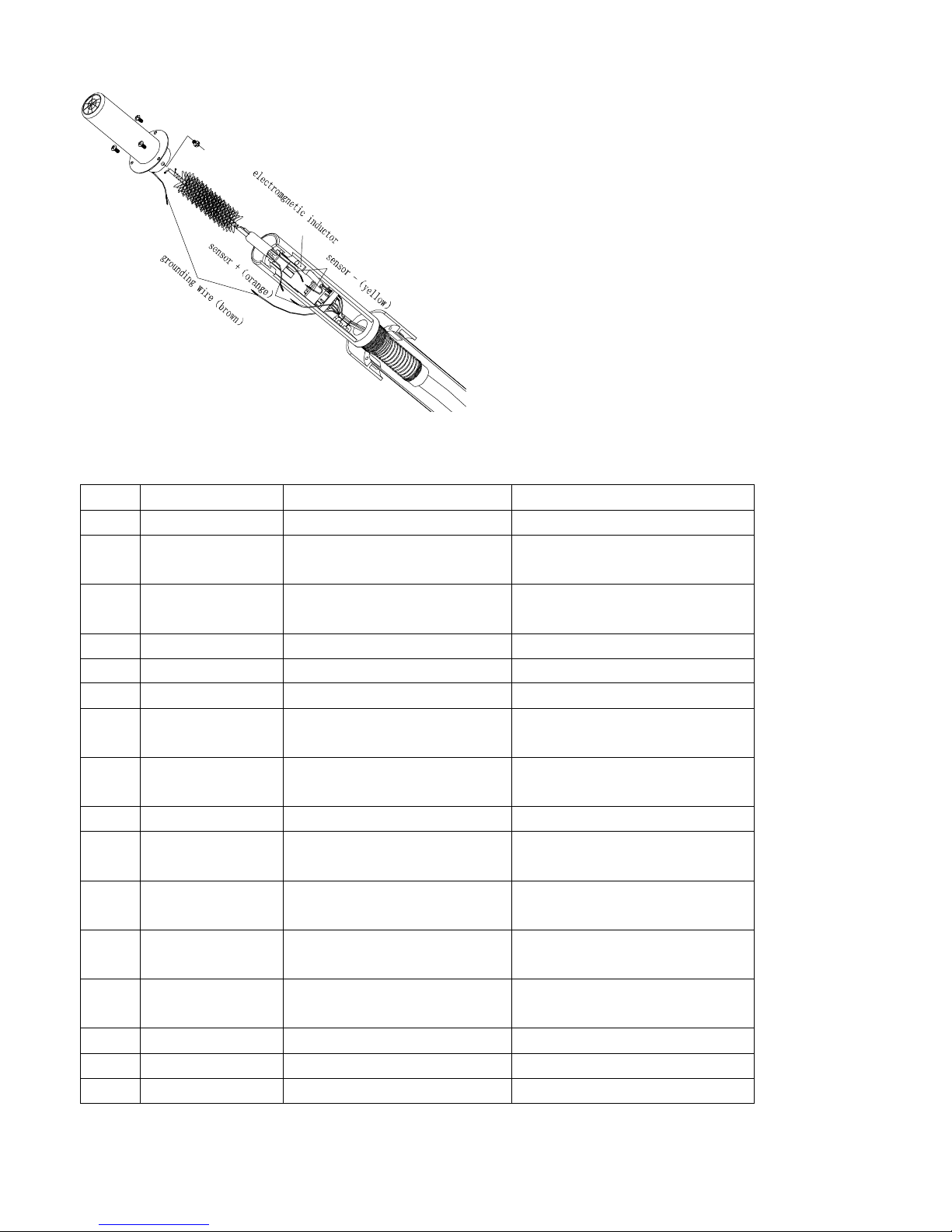
5.Replacement of Heating Element
1. Remove the anti-folding spring on the handle assembly.
2. As shown in the diagram, remove the three screws used to secure the steel
tube. Pull the steel tube out from the handle housing.
3. Loosen screws on the steel tube and also inside the frame of the handle,
get out the tube assembly. Make sure not to drop or lose the quarts-glass
and heat-insulator.
4. Disconnect the grounding wire, sensor connector and heater connector, get
out the heater assembly (including heating element and sensor)
5.Insert a new heater, then connect the heater connector. As sensor wires have
slopes, it is necessary to connect wires with the same colors.
6.Reassemble the handle.

5
6.Replaceable Parts
No Part Number Part Name Description
1 47131 Air Pump 24 VDC
2 47149 Heater (Heating element
and sensor assembly)
560W 220V/230V
3 47150 Heater (Heating element
and sensor assembly)
560W 110V
4 18050.220 Transformer 220VAC
5 18050.110 Transformer 110VAC
6 47151 Handle Holder Assembly
7 47152 Handle Assembly Heater, Plastic Handle,
Tube Assembly, Hose etc.
8 47153 Plastic Handle Inner and outer housing 1
pcs each
9 25043 Hose Silicon Gel
10 47154 Steel tube Assembly Steel tube, Insulator
etc.
11 47157 Electromagnetic
Inductor switch
12 47158 PCB Digital display CPU
controlled temperature
12 47168 PCB LED display normal
controlled temperature
13 24058 Nozzle ф8mm Single
14 24057 Nozzle ф12mm Single
15 24059 Nozzle ф6mm Single
*Specifications and design subject to change without notice.
Table of contents