MAG TOOLS BK104B User manual

BK104B and BK110B 06/01/2021
Maximum Capacity........................... 4-Ton @ 7,250 psig ......................10-Ton @ 7,250 psig
Ram Minimum Height..................................10.51"....................................................... 12.68"
Stroke.......................................................... 4.72"......................................................... 5.12"
Fluid Capacity ........................................... 12.8-oz. ......................................................22-oz.
Weight ...................................................... 40.7-Lbs. ................................................69.3-Lbs.
SPECIFICATIONS
OWNER'S MANUAL
BK104B AND BK110B
4-TON AND 10-TON
CAPACITY BODY REPAIR KIT
BK104B
4-TON
BK110B
10-TON
BK104B BK110B
S
A
F
E
T
Y
S
T
A
N
D
A
R
D
C
O
M
P
L
I
E
S
I
T
H
W
ASME PASE-2019
© 2021 Mac Tools

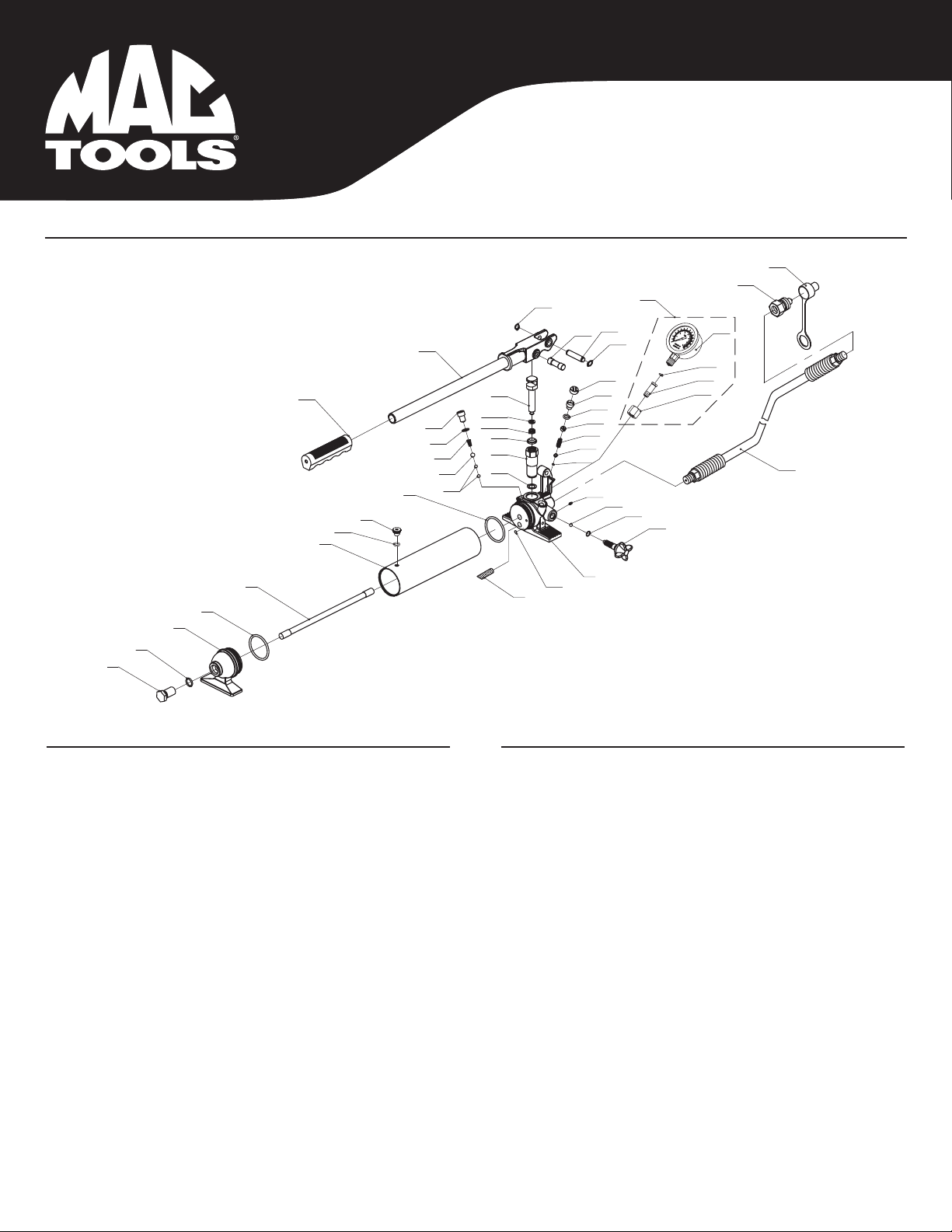
BK104B and BK110B 2 06/01/2021
WARNING INFORMATION
This is the safety alert symbol. It is used to alert you to
potential personal injury hazards. Obey all safety messages
that follow this symbol to avoid possible injury or death.
IMPORTANT: READ THESE INSTRUCTIONS BEFORE OPERATING
BEFORE USING THIS DEVICE, READ THIS MANUAL COMPLETELY AND THOROUGHLY, UNDERSTAND ITS OPERATING PROCEDURES, SAFETY WARNINGS
AND MAINTENANCE REQUIREMENTS. SAVE THESE INSTRUCTIONS.
It is the responsibility of the owner to make sure all personnel read this manual prior to using this Portable Hydraulic Power Kit. It is also the responsibility of the
kit owner to keep this manual intact and in a convenient location for all to see and read. If the manual or product labels are lost or not legible, contact Mac Tools
for replacements. If the operator is not fluent in English, the product and safety instructions shall be read to and discussed with the operator in the operator's
native language by the purchaser/owner or his designee, making sure that the operator comprehends its contents.
This product is intended only for use in the repair of vehicle bodies and frames. Do not use or modify this product for any other purpose than that for which it
was designed without consulting the manufacturer's authorized representative. The use of portable automotive lifting devices are subject to certain hazards
that cannot be prevented by mechanical means, but only by the exercise of intelligence, care, and common sense. It is therefore essential to have owners and
personnel involved in the use and operation of the equipment who are careful, competent, trained, and qualified in the safe operation of the equipment and its
proper use. Examples of hazards are dropping, tipping or slipping of loads caused primarily by improperly securing loads, overloading, off-centered loads, use
on other than hard level surfaces, and using equipment for a purpose for which it was not designed.
METHODS TO AVOID HAZARDOUS SITUATIONS
• Read, study, understand, and follow all instructions before operating this device.
• The kit owner is responsible for the kit being used in accordance with OSHA, state, and local safety standards.
• User and bystanders must wear eye protection that meets ANSI Z87.1 and OSHA standards.
• Do not use beyond rated capacity.
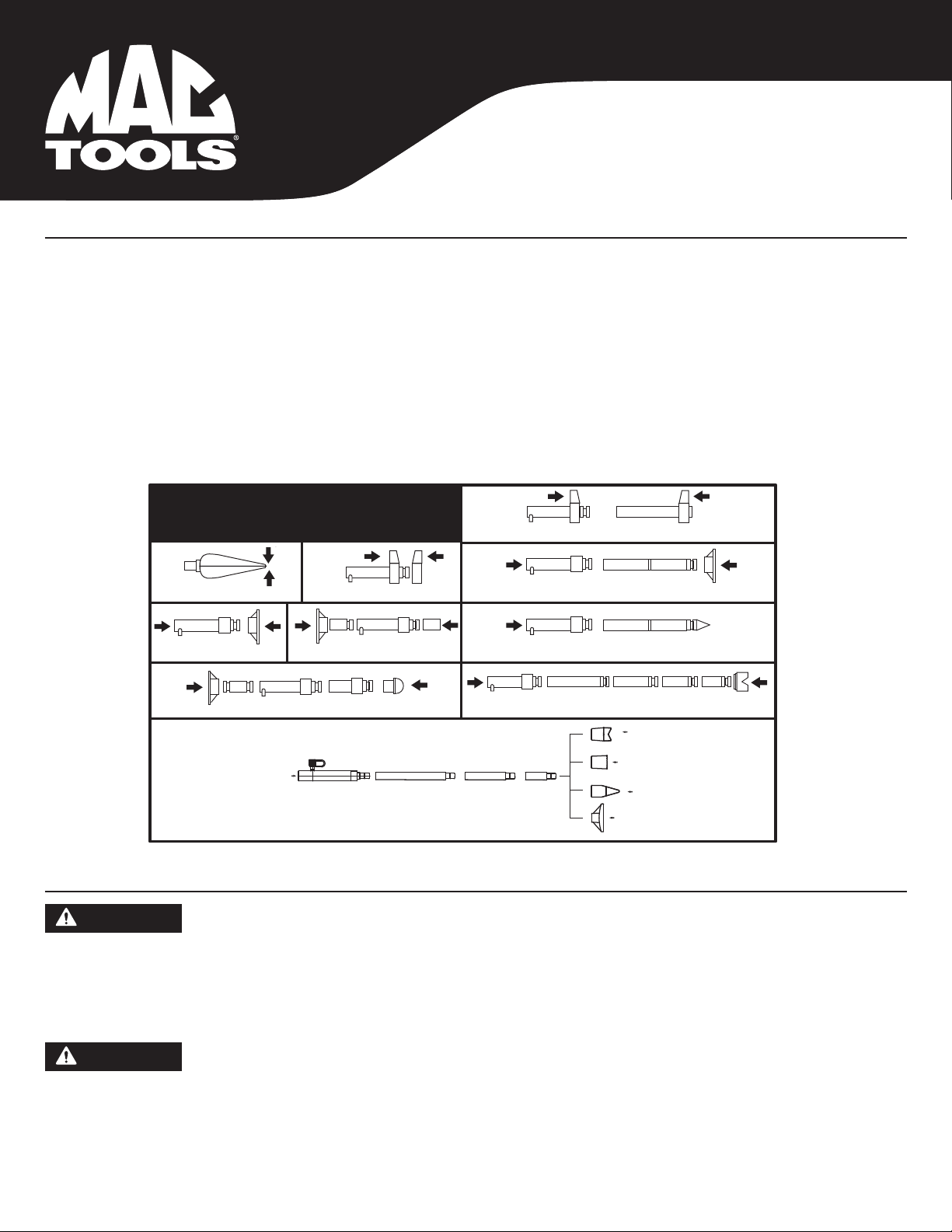
• When attachments and adapters are used with the kit, the rated capacity of the kit shall be no greater than the rated capacity of the lowest rated
component or combination of components that makes up the kit. Refer to the Owner’s Manual section titled “APPLYING FORCE” for typical
applications and corresponding load capacities.
• Use a pressure gauge that indicates force applied.
• Spreader Ram is rated at 1/2 ton capacity.
• Rubber Heads are rated at 1/2 ton capacity in the 4 ton kit and 1 ton capacity in the 10 ton kit.
• Do not overextend the rams.
• When using extension tubes, position the shortest tube farthest away from the cylinder.
• Attachments and extension tubes must be aligned and fully engaged so the ram force is straight and avoids off-center conditions.
• Before operating, tighten all hose, gauge and manifold connections so they are secure and leak free. Do not over tighten or it may cause premature
thread failure or split pressure fittings. Tighten all hose quick disconnect fittings by hand only.
• Do not subject the hose to extreme heat or cold, sharp surfaces, abrasion, impact, kinking, twisting, curling, bending or any condition that restricts
or affects fluid flow.
• Make sure setup is stable and secure before performing any work.
• Use this kit for the intended purpose of vehicle body/frame repair only.
• Only components supplied with this kit shall be used with this kit.
• No alterations or modifications shall be made to any of the kit components.
• Failure to follow these warnings could result in death or serious injury and/or property damage.
WARNING: This product can expose you to chemicals including nickel, which is known to the State of California to cause cancer and birth defects
or other reproductive harm. For more information go to www.P65Warnings.ca.gov.
WARNING: Indicates a hazardous situation
which, if not avoided, could result in death
or serious injury.
WARNING
WARNING
WARNING
THIS INSTRUCTION MANUAL USES THE FOLLOWING SYMBOLS AND DEFINITIONS TO ALERT YOU TO HAZARDOUS CONDITIONS WHICH MAY CREATE A RISK
OF PERSONAL INJURY AND/OR PROPERTY DAMAGE.

BK104B and BK110B 3 06/01/2021
SETUP INSTRUCTIONS
BK104B AND BK110B
4-TON AND 10-TON
CAPACITY BODY REPAIR KIT
Please refer to the exploded view drawings on page 6-11 in this manual in order to identify parts:
1. Refer to the parts list and drawing in this manual to identify parts mentioned in this setup procedure.
2. Before installing the force gage (P39) remove the plug A in the hose end of the pump (01). Thread the gage into the gage fitting (P41) and connect with the
receiver (P42) by turning it clockwise. Make sure the connection is tight to prevent leakage.
3. Open the release valve (P29) by turning it counterclockwise until it stops, then pump the handle 4 or 5 full incremented pump strokes to purge air from the
hydraulic system.
4. Install ram (02) or spreader (03) at the end of hose (P30) and secure the quick disconnect fittings together by hand tightening the threaded sleeve
(R06-4T & R15-10T) on the female coupler (R15-4T & R16-10T) to the male coupler (P31) at the end of the hose (P30).
OPERATING INSTRUCTIONS
1. Study the work to be done in order to determine the type ram and other attachments you will be using. Consult the enclosed chart titled “Applicable
force for component set ups” in order to determine the maximum allowable force to be used in your specific setup. All rams have female hose
disconnects attached to them, and the end of the hose has the male quick disconnect attached to it. Insert the end of the hose (P30) all the way in to the
ram’s female quick disconnect (R15). Slide the female connector’s threaded sleeve (R06-4T & R15-10T) on to the threads at the end of the hose (P30) and
hand tighten. Never use any tools to tighten this connection.
2. Consult this Owner’s Manual section titled APPLICABLE FORCE FOR COMPONENT SET UPS for typical attachment and extension tube setups and pay
very close attention to the corresponding load ratings of certain attachment connections. The use of extension tubes, ram or plunger toes greatly reduces
the hydraulic system’s capacity. When using extension tubes, put the shortest tubes on the ends of the setup.
3. The pump (1) may be operated in the horizontal or vertical position but the pump (1) must point down when used in the vertical position.
4. Make sure all hydraulic and attachment connections are fully engaged and tight so ram force is straight in order to avoid off-center load conditions.
5. During setup, make sure the hose routing avoids kinks, twists, curls or bends that will impede hydraulic fluid flow. Do not use the hose (P30) as a means
to carry the kit components. Do not subject the hose (P30) to any hazards such as fire, extreme heat or cold, sharp surfaces, or heavy impact. IF A HOSE
(P30) RUPTURES, BURSTS, OR NEEDS TO BE DISCONNECTED, IMMEDIATELY SHUT THE PUMP (1) OFF AND OPEN THE RELEASE VALVE (P29) TO RELEASE
HYDRAULIC PRESSURE. NEVER GRASP A LEAKING PRESSURIZED HOSE, FITTING OR COMPONENT WITH YOUR HANDS OR SUFFER SERIOUS INJURY.
6. Always use the pressure gauge (14) to make sure you are within the required force range when operating the system.
7. In order to pump the ram (2), it will be necessary to turn the release valve knob (P29) in a clockwise direction until tight. Tighten by hand only.
8. Pumping the handle (P34) up and down transfers the hydraulic fluid from the pump’s reservoir (P6), through the hose (P30), in to the cylinder and extends
the ram with each incremental pump stroke.
CONSEQUENCES OF NOT AVOIDING HAZARDOUS SITUATIONS
Failure to read this manual completely and thoroughly, failure to understand its OPERATING INSTRUCTIONS, SAFETY WARNINGS, MAINTENANCE INSTRUCTIONS
and comply with them, and failure to comply with the METHODS TO AVOID HAZARDOUS SITUATIONS could cause accidents resulting in serious or fatal personal
injury and/or property damage.
WARNING
Failure to follow these Setup Instructions may result in serious injury or death, and/or property damage.
Failure to follow these Operating Instructions may result in serious injury or death, and/or property damage.
WARNING
WARNING
P39
P40
P41
P42

BK104B and BK110B 4 06/01/2021
BK104B AND BK110B
4-TON AND 10-TON
CAPACITY BODY REPAIR KIT
PREVENTATIVE MAINTENANCE
1. Always store the kit in a well protected area where it will not be exposed to inclement weather, corrosive vapors, abrasive dust, or any other harmful
elements. The jack must be cleaned of water, snow, sand, grit, oil, grease or other foreign matter before using.
2. Based on continuous engagement and disengagement of the hose from the cylinder, eventually it will become necessary to add hydraulic fluid to the
pump’s reservoir. Completely retract the ram before adding hydraulic fluid. Do not overfill in order to avoid personal injury and hydraulic malfunction.
Use only hydraulic jack oil. Other fluids will cause damage to the hydraulic seals.
In order to prevent seal damage and kit failure, never use alcohol, hydraulic brake fluid or transmission oil in the pump.
3. Every kit owner is responsible for keeping the kit labels clean and readable. Use a mild soap solution to wash external surfaces of the kit components
but not any moving hydraulic components.
4. Do not attempt to make any hydraulic repairs unless you are a qualified hydraulic repair person that is familiar with this equipment. Repairs must be
performed by an authorized service center.
OPERATING INSTRUCTIONS (CONTINUED)
9. To release the pressure and return the ram (2) back in to its cylinder (R13-4T & R14-10T) , turn the release valve knob (P29) in a counterclockwise direction
very slowly. Turning the release valve knob (P29) slowly will determine the speed in which the ram (2) will retract back into its cylinder (R13-4T & R14-10T).
IMPORTANT: The pump includes an overload valve that will activate at the pump’s rated capacity only. If the setup requires a reduced rating, the operator is
responsible for using the gauge to determine when to stop pumping since the overload valve (P24) is set to a higher rating.
10. Make sure the ram (2) is completely retracted inside its cylinder (R13-4T & R14-10T) before disconnecting the hose from the cylinder.
11. The the hose (P30) and the ram (2) are repeatedly disconnected and exposed to shop or work place floors that are covered with dirt and debris. It is
important to use the dust caps (P32) provided to prevent contaminants from entering the air and hydraulic systems.
12. Based on continuous engagement and disengagement of the hose (P30) from the cylinder (R13-4T & R14-10T), eventually it will become necessary to
add hydraulic fluid to the pump’s reservoir (P6). Completely retract the ram before adding hydraulic fluid. Do not overfill in order to avoid personal injury and
hydraulic malfunction. Use only hydraulic jack oil, Chevron Hydraulic Oil AW ISO 32 or its equivalent Unocal Unax AW 150. Other fluids will cause damage to
the hydraulic seals.
Spreader Capacity
100% of Ram Capacity 100% of Ram Capacity
100% of Plunger Toe Capacity
25% of Ram Capacity
100% of Rubber Head Capacity
50% of Plunger Toe Capacity
25% of Ram Capacity
6% of Ram Capacity
APPLICABLE FORCE
FOR COMPONENT SET UPS
12% of Ram Capacity
Failure to follow these Preventative Maintenance instructions may result in serious injury or death, and/or property damage.
WARNING
WARNING

BK104B and BK110B 5 06/01/2021
BK104B AND BK110B
4-TON AND 10-TON
CAPACITY BODY REPAIR KIT
TROUBLESHOOTING
Important: If repairs are necessary they must be performed in a dirt-free environment by qualified personnel who are familiar with this equipment.
PROBLEM ACTION
1. Ram will not lift rated Load. Turn reservoir fill screw (P7) counterclockwise two complete revolutions and wait 10 seconds.
Turn screw clockwise until tight and proceed to pump. If that does not fix the problem check
the pump reservoir's fluid level. The proper amount of fluid should be BK104B - 12.8 ounces
and BK110B - 22 ounces. Use only hydraulic jack oil. For any other problems contact Mac
Tools®authorized hydraulic service center.
2. Unit will not sustain rated load or feels “spongy” under rated load. Purge air from hydraulic system as above.
3. Unit will not lift to full height. Purge air from hydraulic system as above.
4. Handle tends to raise up while the unit is under rated load. Pump the handle rapidly several times to push oil past ball valves in power unit.
5. Unit still does not operate. Contact Mac Tools®authorized hydraulic service center.
PROPER STORAGE
It is recommended that the kit be stored in a dry location with all wheels touching the ground on a relatively level surface.

BK104B and BK110B 6 06/01/2021
4-TON PARTS DIAGRAM
BK104B
4-TON CAPACITY
BODY REPAIR KIT
Only items identified by part number are available for purchase.
Item No. Part No. Description Qty.
01 RS4TPAR Pump (Incl. Hose) 1
RSHS Hose 1
02 RS4TR Ram 1
03 RSSPRAR Spreader 1
04 RS4T01 Case 1
05.1 RS4T02.1 3.23" (82mm) Extension 1
05.2 RS4T02.2 5.04"(128mm) Extension 1
05.3 RS4T02.3 8.50"(216mm) Extension 1
05.4 RS4T02.4 16.54"(420mm) Extension 1
05.5 RS4T02.5 19.49"(495mm) Extension 1
Item No. Part No. Description Qty.
06 RS4T04A Ram Toe 1
07 RS4T05 Plunger Toe 1
08 RS4T06 Wedge Head 1
09 RS4T07 V-Base 1
10 RS4T08 Male Connector 1
11 RS4T09 Serrated Saddle 1
12 RS4T10 Rubber Head 1
13 RS4T03 Flat Base 1
14 RSPGA Pressure Gauge Assembly 1
RSBK104BPLK Product Label Kit (not shown) 1
P39
P40
P41
P42
14

BK104B and BK110B 7 06/01/2021
*Items identified by an asterisk are available in pump seal kit, RS4TPSKA.
NOTE: Items which are not identified by a part number or with an asterisk are not available separately.
Item No. Part No. Description Qty.
P1 Screw 1
P2 * O-ring 1
P3 RS4TPFR Pump Foot - Red 1
P4 * O-ring 2
P5 Tie Rod 1
P6 Reservoir 1
P7 Breather Screw 1
P8 Oil Filter 1
P9 Valve Block 1
P10 * Ball 3
P11 * Ball 1
P12 * Spring 1
P13 * Washer 1
P14 Plug Screw 1
P15 * Copper Ring 1
P16 * Piston Seat 1
P17 * Anti-dust Ring 1
P18 * Sealing Ring (incl 18-1 & 18-2) 1
P19 Screw 1
P20 Piston 1
P21 * Ball 1
Item No. Part No. Description Qty.
P22 * Ball Cup 1
P23 * Spring 1
P24 * Screw 1
P25 * O-ring 2
P26 Screw 1
P27 Screw Cap 1
P28 * O-ring 1
P29 RSP15 Release Valve - Red 1
P30 RSHS Hose 1
P31 RSP17 Male Coupler 1
P32 RSP18 Hose Dust Cover 1
P33 Magnet 1
P34 RS4THNDLR Handle w/Grip - Red 1
P35 Handle Grip 1
P36 Pin 1
P37 Sealing Ring 2
P38 Pin 1
P39 RSPGA Pressure Gauge (incl P39 - P42) 1
P40 O-ring 1
P41 Gauge Fitting 1
P42 Nut 1
4-TON PUMP PARTS DIAGRAM
BK104B
4-TON CAPACITY
BODY REPAIR KIT
P1
P2
P3
P4
P5
P6
P25
P7
P10
P11
P12
P13
P14
P20
P18-1
P18-2
P17
P16
P15
P4
P8
P9
P10
P28
P29
P21
P22
P23
P24
P25
P26
P27
P31
P32
P30
P19
P34
P35
P36 P38
P37
P33
P37
P39
P40
P41
P42
P39

BK104B and BK110B 8 06/01/2021
*Items identified by an asterisk are available in Ram Seal Kit, RS4TRSKA.
NOTE: Items which are not identified by a part number or with an asterisk
are not available separately.
*Items identified by an asterisk are available in Spreader Seal Kit, RSSPRASK.
NOTE: Items which are not identified by a part number or with an asterisk are not available separately.
Item No. Part No. Description Qty.
R01 RS4TR01 Cover 1
R02 Circlip 1
R03 Piston Rod 1
R04 * Circlip 1
R05 * Bushing 1
R06 Nut 1
R07 * Sealing Ring Set 1
R08 * Retaining Ring 1
R09 Spring 1
R10 Screw 1
R11 RS4TR12 Protection Cap 1
R12 Limit Ring 1
R13 Cylinder 1
R14 Screw 1
R15 Female Coupler 1
R16 O-ring 1
R17 Dust Cover 1
R18 Sealing Ring 1
N/S RSRCPLR Ram Coupler (incl R06, R15–R18) 1
Item No. Part No. Description Qty.
S1 Pin 1
S2 Circlip 1
S3 Movable Jaw 1
S4 Spring 1
S5 Fixed Jaw 1
S6 Piston 1
S7 * Cup Seal 1
S8 * O-ring 1
S9 End Cap 1
S10 Nut 1
S11 Coupler 1
S12 O-ring 1
S13 Dust Cover 1
S14 Sealing ring 1
N/S RSSPRCPLR Spreader Coupler (incl S10 – S14) 1
4-TON RAM PARTS DIAGRAM
4-TON SPREADER PARTS DIAGRAM
BK104B
4-TON CAPACITY
BODY REPAIR KIT

BK104B and BK110B 9 06/01/2021
10-TON PARTS DIAGRAM
BK110B
10-TON CAPACITY
BODY REPAIR KIT
Only items identified by part number are available for purchase.
Item No. Part No. Description Qty.
01 RS10TPAR Pump w/Hose 1
RSHS Hose 1
02 RS10TR Ram 1
03 RSSPRAR Spreader 1
04 RS10T01 Case 1
RS10T01WH Wheel for Case 2
5.1 RS10T02.1 4.33” (110mm) Extension 1
5.2 RS10T02.2 10.43” (265mm) Extension 1
5.3 RS10T02.3 14.37” (365mm) Extension 1
5.4 RS10T02.4 20.47” (520mm) Extension 1
Item No. Part No. Description Qty.
06 RS10T04A Ram Toe 1
07 RS10T05 Plunger Toe 1
08 RS10T06 Wedge Head 1
09 RS10T07 V-Base 1
10 RS10T08 Male Connector 1
11 RS10T09 Serrated Saddle 1
12 RS10T10 Rubber Head 1
13 RS10T03 Flat Base 1
14 RSPGA Pressure Gauge Assembly 1
(incl. P39-P42)
N/S RSBK110BPLK Product Label Kit 1
06 07 08 09 10 11
05.1
05.2
05.3
05.4
12 13
04
01
02
03
P39
P40
P41
P42
14

BK104B and BK110B 10 06/01/2021
*Items identified by an asterisk are available in pump seal kit, RS10TPSKA.
NOTE: Items which are not identified by a part number or with an asterisk are not available separately.
Item No. Part No. Description Qty.
P1 Screw 1
P2 * O-ring 1
P3 RS10TPFR Pump Foot - Red 1
P4 * O-ring 2
P5 Tie Rod 1
P6 Reservoir 1
P7 Breather Screw 1
P8 Oil Filter 1
P9 Valve Block 1
P10 * Ball 3
P11 * Ball 1
P12 * Spring 1
P13 * Washer 1
P14 Plug Screw 1
P15 * Copper Ring 1
P16 * Piston Seat 1
P17 * Anti-dust Ring 1
P18 * Sealing Ring (incl 18-1 & 18-2) 1
P19 Screw 1
P20 Piston 1
P21 * Ball 1
Item No. Part No. Description Qty.
P22 * Ball Cup 1
P23 * Spring 1
P24 * Screw 1
P25 * O-ring 2
P26 Screw 1
P27 Screw Cap 1
P28 * O-ring 1
P29 RSP15 Release Valve - Red 1
P30 RSHS Hose 1
P31 RSP17 Male Coupler 1
P32 RSP18 Hose Dust Cover 1
P33 Magnet 1
P34 RS10THNDLR Handle w/Grip - Red 1
P35 Handle Grip 1
P36 Pin 1
P37 Sealing Ring 2
P38 Pin 1
P39 RSPGA Pressure Gauge (incl P39 - P42) 1
P40 O-ring 1
P41 Gauge Fitting 1
P42 Nut 1
10-TON PUMP PARTS DIAGRAM
BK110B
10-TON CAPACITY
BODY REPAIR KIT
P1
P2
P3
P4
P5
P6
P25
P7
P10
P11
P12
P13
P14
P20
P18-1
P18-2
P17
P16
P15
P4
P8
P9
P10
P28
P29
P21
P22
P23
P24
P25
P26
P27
P31
P32
P30
P19
P34
P35
P36 P38
P37
P33
P37
P39
P40
P41
P42
P39

BK104B and BK110B 11 06/01/2021
10-TON RAM PARTS DIAGRAM
10-TON SPREADER PARTS DIAGRAM
BK110B
10-TON CAPACITY
BODY REPAIR KIT
*Items identified by an asterisk are available in Ram Seal Kit, RS10TRSKA.
NOTE: Items which are not identified by a part number or with an asterisk are
not available separately.
*Items identified by an asterisk are available in Spreader Seal Kit, RSSPRASK.
NOTE: Items which are not identified by a part number or with an asterisk are not available separately.
Item No. Part No. Description Qty.
R01 RS10TR01 Cover 1
R02 Circlip 1
R03 Piston Rod 1
R04 * Circlip 1
R05 * Bushing 1
R06 * Nut 1
R07 Sealing Ring Set 1
R08 * Circlip 1
R09 Spring 1
R10 Screw 1
R11 RS10TR12 Protection Cap 1
R12 Limit Ring 1
R13 Cylinder 1
R14 Screw 1
R15 Female Coupler 1
R16 O-ring 1
R17 Dust Cover 1
R18 Sealing Ring 1
N/S RSRCPLR Ram Coupler (incl R15–R18) 1
Item No. Part No. Description Qty.
S1 Pin 1
S2 Circlip 1
S3 Movable Jaw 1
S4 Spring 1
S5 Fixed Jaw 1
S6 Piston 1
S7 * Cup Seal 1
S8 * O-ring 1
S9 End Cap 1
S10 Nut 1
S11 Coupler 1
S12 O-ring 1
S13 Dust Cover 1
S14 Sealing ring 1
N/S RSSPRCPLR Spreader Coupler (incl S10 – S14) 1

BK104B and BK110B 12 06/01/2021
MAC TOOLS WARRANTS TO ITS CUSTOMERS THAT THE COMPANY’S MAC TOOLS BRANDED PRODUCTS ARE FREE FROM DEFECTS IN WORKMANSHIP
AND MATERIALS.
Mac Tools will repair or replace its Mac Tools branded products which fail to give satisfactory service due to defective workmanship or materials, based upon
the terms and conditions of the following described warranty plans attributed to that specific product. This product carries a ONE-YEAR warranty. During this
warranty period, Mac Tools will repair or replace at our option any part or unit which proves to be defective in material or workmanship.
Other important warranty information:
This warranty does not cover damage to equipment or tools arising from alteration, abuse, misuse, damage and does not cover any repairs or replacement
made by anyone other than Mac Tools. The foregoing obligation is Mac Tools sole liability under this or any implied warranty and under no circumstances shall
we be liable for any incidental or consequential damages.
Note: Some states do not allow the exclusion or limitation of incidental or consequential damages, so the above limitation or exclusion may not apply to you.
If you have any questions about warranty service, please contact Mac Tools. This warranty gives you specific legal rights and you may also have other rights
which vary from state to state.
LIMITED WARRANTY
BK104B AND BK110B
4-TON AND 10-TON
CAPACITY BODY REPAIR KIT
This manual suits for next models
1
Table of contents
Other MAG TOOLS Power Tools manuals
Popular Power Tools manuals by other brands

Monti
Monti Bristle Blaster Electric operating instructions

Jet
Jet JDP-370 operating instructions

Stocker
Stocker Kantia E-22 TR user manual

Balcrank
Balcrank Roughneck II 4110-022 Operation, installation, maintenance and repair guide

Ares
Ares 43012 Operation manual

APT
APT RP 160 Safety and operating instructions