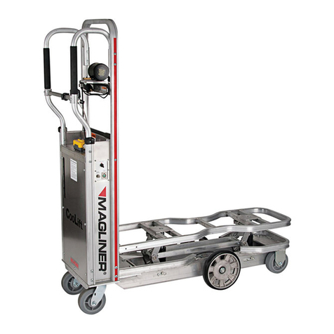
Magliner CooLift CMH Series User manual

1-800-MAGLINE (624-5463) Page 1 www.magliner.com
CooLift®
Serial #: _________________________________
Date of Purchase: ________________________
Owner’s Manual
IMPORTANT: Read entire manual before operating
For CooLift models with manual hydraulic lift (CMH-- models)

1-800-MAGLINE (624-5463) Page 2 www.magliner.com
CooLift®
Warranty
Magliner products have a one (1) year warranty (unless otherwise specied) from the date of
purchase against defects in workmanship or material. Any part or component, except items covered
by warranties of other manufacturers, returned to the factory or service center freight prepaid
by the owner, found upon examination by Magline, Inc. to be defective or the result of improper
workmanship by the factory will be repaired or replaced without charge and returned to the owner
freight prepaid by Magline, Inc.
Alterations of Magliner products void any warranty or liability on the part of Magline, Inc. Magline,
Inc. does not guarantee product capacity if alterations are made.

1-800-MAGLINE (624-5463) Page 3 www.magliner.com
CooLift®
Table of Contents
Introduction, Safety Instructions ...........................................................................................................4
Operating Labels ...................................................................................................................................5
General Specications ..........................................................................................................................6
CooLift Pallet .........................................................................................................................................7
Controls -- General Operation ..........................................................................................................8-11
Troubleshooting...................................................................................................................................12
Replacement Parts List ................................................................................................................. 13-14
Inspection / Maintenance Checklist................................................................................................ 15-20

1-800-MAGLINE (624-5463) Page 4 www.magliner.com
CooLift®
Thank you for purchasing the Magliner CooLift! If you have any questions regarding your new
Magliner product please call our customer service department at 1-800-MAGLINE (624-5463) or
(989) 512-1000. Please read this manual thoroughly to become familiar with the safe operation and
maintenance of your new Magliner CooLift.
General Safety Instructions
• Carefully read this entire manual before using your Magliner CooLift.
• Keep hands and feet away from all moving parts.
• Always stand clear of lifting platform area when operating.
• Do not attempt to use the Magliner CooLift on a truck ramp.
• Engage the foot brake whenever in a stopped position.
• Keep the Magliner CooLift in an upright position at all times.
• Do not utilize Magliner CooLift as a lifting device for anything other than a CooLift pallet.
• Do not use the Magliner CooLift to transport people.
• A routine check of the CooLift should be performed daily that includes, but not limited to:
checking for any leaks in the hydraulic or brake system; making sure the containment strap
functions correctly; making sure the lift deck raises and lowers smoothly without excessive
slowing or shuddering; checking the speed control brake system to ensure proper slowing
and stopping functions; checking the foot brake system to ensure it prevents rear casters
from rotation and swivel.
• Always use the containment strap when moving loads with the Magliner CooLift.
• When transporting a load, always use the handles provided at the user end of the CooLift
in order to provide quick access to the braking system should immediate stopping be
required.
• Operator should be positioned uphill from CooLift when descending on natural grades,
sloping or uneven surfaces.
• Use hand brake to control speed.
• Avoid making sharp turns.
• Do not exceed the 1,000 lbs. capacity limit.
• Brake and hydraulic uids are a slip hazard on any ooring surface; if a leak occurs it
should be cleaned up immediately and completely.

1-800-MAGLINE (624-5463) Page 5 www.magliner.com
CooLift®
Please follow the reminder labels found on your CooLift unit.
NO FORK
Always stand clear
of lifting platform
area
when operating
Keep hands and feet
clear of lifting platform
Safety Instructions
• Read and understand operating instructions
before using
• Always inspect CooLift and pallets for damage
before using. Do not use if there are signs of
damage, improper maintenance or load shift
• Do not exceed capacity limit
• NO RIDING — Riding on the CooLift could
cause serious injury
• DO NOT USE ON TRUCK RAMPS
• Use caution on natural grades; operator
should be positioned uphill from cart when
descending, use brake to control speed, no
sharp turns
• Always apply holding brake and lower lift
before unloading pallet or leaving CooLift
unattended
WARNING
WARNING

1-800-MAGLINE (624-5463) Page 6 www.magliner.com
CooLift®
General Specications CMH43
Corresponding pallet size 43 inch
Capacity 1,000 lbs
Weight 182 lbs
Overall height 65 inches
Overall width 19 inches
Overall depth 60 inches
Operating temperature* -20 to 120°F
*NOTE: When the outside temperature is below 30°F the CooLift should not be left inside the truck
overnight and should never be left inside a freezer or a cooler for extended periods of time. Extended
exposure to subfreezing temperatures will adversely aect CooLift performance and increase cycle
time.
CooLift with
bulk head
CMH43

1-800-MAGLINE (624-5463) Page 7 www.magliner.com
CooLift®
Pallets
Buttons for attaching beginning of
stretch wrap
General Pallet Information:
• Always load within capacity limit.
• Always load within pallet footprint; do not allow load to hang over pallet.
• CAUTION: When using any multiple load handling system (such as a triple-double) to move
the CooLift pallets, do not spread the forks while underneath pallet as it may result in pallet
failure.
• Store in upright position in cool, dry location.
• Do not drop.
• Do not stand upon.
• Wash with mild soap and water.
• Do not use if damaged.
• Make sure to interlock empty pallets when stacking.
• Only stack pallets when empty.
• Do not make modications.
• Secure load before transporting.
• Use for intended purpose only.
Ergonomically placed hand
holes for easy carrying
Size Capacity with
Manual CooLift
Part
Number
43” pallet 1,000 309344
Pallet design allows
for any size pallet to
stack on top of any
other size pallet.
Anti-slip tape
reduces product
from shifting

1-800-MAGLINE (624-5463) Page 8 www.magliner.com
CooLift®
User Controls
A) Speed Control Brake Lever – used for slowing and stopping the momentum of the CooLift. This brake
does not act as a parking brake.
B) Foot Brake Lever - the foot brake is used as a parking brake for when the CooLift is in transit in the back
of a vehicle, or if the CooLift is left unattended.
C) Pump release valve – when valve is closed, the deck can be lifted. Open the valve to release the deck.
D) Containment Strap – should be used to secure loads during transport.
E) Operator Handles – foam cushioned, ergonomic handles for lift control.
F) Manual Pump Handle – handle and retention strap for when not in use.
G) Lift Assist Handle (optional) - handles pivot upward to give additional leverage when lifting back of CooLift
Deck Operation of the Magliner Manual CooLift
The CooLift deck is raised and lowered using the hand pump handle provided with the unit.
To raise the deck:
1. Rotate the valve handle toward the back of the CooLift (i.e. clockwise direction).
2. Carefully remove the retention strap from the pump handle.
3. Make sure the pump handle is securely inserted into the pump handle receiver located at the top of the
pump.
4. Firmly grasp the handle and swing downward until it reaches the limit of travel - this increases pressure
in the hydraulic line to apply lifting force to the deck. Return handle to upright position.
5. Repeat step 3 until the load is lifted to desired height.
6. Replace the retention strap on the pump handle in the upright position.
Note: The heavier the load, the more pumps it may take to raise the deck to the top position. With a 1,000
lbs. load, this could take approximately 18 pumps of the handle to lift the deck to the top position.
To lower the deck:
1. Rotate the valve handle toward the front of the CooLift (i.e. counter-clockwise direction).
2. The rate of descent can be controlled by how much the valve handle is rotated toward the front of the
CooLift. The deck can be lowered part way and then held in place by rotating the handle toward the back
of the unit until descent stops.
3. The deck will lower into the lowest position.
Operating the Foot Brake
The foot brake prevents the rear casters from rotating and from swiveling.
To engage, press down on the foot pedal until it locks in the down (locked) position. To disengage, pull up on
the foot pedal until it is released and in the up (unlocked) position.

1-800-MAGLINE (624-5463) Page 9 www.magliner.com
CooLift®
D
C
A
B
F
E
G

1-800-MAGLINE (624-5463) Page 10 www.magliner.com
CooLift®
General Operation of the Magliner CooLift
A) Storage and Use of Foot Brake
1) Engage the foot brake whenever leaving the CooLift unattended.
2) Pallets on the Magliner CooLift should always be in the down position when not moving.
3) Keep hands, feet and all items clear of the moving parts of the CooLift.
4) Never place hands or feet under a loaded elevated pallet.
5) Store the CooLift on a hard level surface.
CooLift with product strapped to deck
Front Underside View
B) Loading a pallet on the Magliner CooLift
1) Make sure CooLift deck is in down position.
2) Push the CooLift under the pallet until fully inserted and the back of the pallet is touching
the back of the cart or the bulk head if one is installed.
3) Rotate the valve handle in the clockwise direction. Pump the manual pump handle until the
deck interlocks with the pallet. Once the deck is in the desired position, return the handle
to the upright position and place the retention strap on the pump handle.
4) Engage the foot brake by pressing the brake down toward the ground or oor until it locks
into the engaged position.
Note: Make sure the deck is in the up position prior to fastening the containment strap.
5) Fasten the containment strap to secure the load by: a) rmly grasping the end of the
strap; b) pulling it out from the roll directly over the center of the load taking care not to twist
the strap; c) extending strap far enough to snap into position; and d) hooking strap to the
containment lock located at the lower front end of the cart (see Front Underside View).
6) The maximum stacking height is 50”. However, never stack a load that is higher than your
line of vision.

1-800-MAGLINE (624-5463) Page 11 www.magliner.com
CooLift®
Figure 1: CooLift secured under a loaded
pallet with the foot brake engaged
Figure 2: CooLift strapped into truck for transport
D) Unloading a pallet from the Magliner CooLift
1) Position the cart in place on a level surface and engage the foot brake.
2) Lower the deck completely by turning the pump valve counter-clockwise.
3) Unlock the containment strap from the lock by lifting the tab and sliding the latch out.
4) Walk the strap back into position on the roll.
5) Disengage the foot brake by pulling the brake lever up until the brake releases.
E) Transporting the Magliner CooLift inside the truck
Note: It is important to keep the CooLift upright at all times.
1) If you are transporting the CooLift on a truck that has loaded pallets, insert the CooLift
completely under a fully loaded pallet and lift the until deck makes contact with the bottom
of the pallet but does not lift it. Engage the foot brake (Figure 1).
2) If there are no loaded pallets on the truck, the CooLift should be parked next to the wall
and strapped in with the foot brake engaged (Figure 2).
C) Transporting a pallet with the Magliner CooLift
1) When transporting a pallet with the CooLift the operator should always use caution on
natural grades. Be positioned uphill from cart when descending, use brake to control speed
and make no sharp turns.
2) Care should be taken to address any sidewalk ramps or door thresholds to help maintain
stability in the load.
3) Use caution at all sloping or uneven surface areas and make any nal positioning changes.
4) Release the manual pump valve by turning the valve handle counter-clockwise until the
CooLift deck has lowered completely. Note: it is possible to have the pallet sitting on
the oor and the deck still engaged to the bottom of the pallet if the deck has not been
completely lowered.
5) Remove the CooLift from under the pallet.

1-800-MAGLINE (624-5463) Page 12 www.magliner.com
CooLift®
The deck lifts to the top position but then gradually lowers.
Is the manual release valve fully closed?
Do you see any leaks in the hydraulic system?
The deck lifts slower than usual.
Is the manual release valve closed all the way?
Do you see any leaks in the hydraulic system?
The brakes are not working or braking unevenly side to side.
Do you see any leaks in the brake system?
If you pump the brake lever several times, does it start working?
Are both of the calipers mounted tightly to the rail?
The deck is in the up position and will not go down.
Is there any foreign matter in the linkage system?
Hydraulic or brake uid has dripped underneath the CooLift deck.
Wipe up any uid that may have leaked using shop towels.
Troubleshooting

1-800-MAGLINE (624-5463) Page 13 www.magliner.com
CooLift®
Replacement Part Description Part Number
Axle - 14.3” long for center CooLift wheels 309020
Axle - 12.9” long for front wheels 309844
Axle mount bracket for center wheels 315009
Back access panel 315081
Brake disc 309050
Brake handle clamp 81207
Brake line assembly (includes brake lever, master cylinder, split brake line, junction box, calipers
and brake pads) PLEASE NOTE: items within assembly not sold separately. 315090
Brake line insert bushing 315098
Brake line nut 315097
Brake pedal kit (includes brake pedal, two 80302 screws and two 80675 lock nuts) 86433
Bulk head for CMH43 and CMH48 models 309790
Bulk head mount 315087
Cable tie 61052
Caster - 6” x 2” swivel, gray TPR with top brake (rear caster) 13085
Caster brake weldment 315117
Caster brake pedal 315107
Caster wheel - 6” x 2” gray at tread (front caster) 130014
Center wheel - 10” x 2” with deep groove ball bearings 309059
Clamp block for axle/brake caliper mount 309022
Containment strap 309152
Containment strap mounting spacer - all models 309150
Containment strap tongue 309133
Cotter pin - 1/8” x 1-1/2” long 81078
Cross brace assembly 315048
Cross brace warning label 98360
Deck weldment 315030
Deep groove ball bearing for center CooLift wheels 309060
Handle assembly with foam handle sleeve 315042
Handle cross brace with rivnuts 315047
Hex head cap screw - 5/16”-18 x 1” long 80011
Hex head cap screw - 5/16”-18 x 1-1/4” long 80012
Hex head cap screw - 5/16”-18 x 2” long 80018
Hex head cap screw - 3/8”-16 x 1” long 80025
Hex head cap screw - 3/8”-16 x 1-1/4” long 80132
Hex head cap screw - 3/8”-16 x 1-1/4” long 80026
Hex head cap screw - 3/8”-16 x 1-1/2” long 79988
Hex lock nut - 1/4”-20 80675
Hex lock nut - 5/16”-18 80676
Hex lock nut - 3/8”-16 80603
Hex lock nut ange - 3/8”-16 80624
Hex socket head cap screw - 5/16”-18 x 1” long 80038
Hydraulic cylinder assembly (includes items below with *) 315094

1-800-MAGLINE (624-5463) Page 14 www.magliner.com
CooLift®
Hydraulic cylinder* 59010
Hydraulic cylinder mount, xed* 315078
Hydraulic cylinder mount, moveable* 315079
Hydraulic tting - 90-degree elbow, 3/8 NPSM female (swivel end) x 3/8 NPTF male end* 55425
Hex socket head cap screw - 3/4”-15 x 1-1/4” long* 80157
Hex socket head cap screw - 1/4”-20 x 3/4” long* 80041
Hydraulic cylinder mount, xed pin 315058
Hydraulic cylinder mount bracket 315076
Hydraulic cylinder mount plate 315075
Hydraulic hose - 3/18” x 6’ long 55424
Knob replacement kit (includes one 315069 knob, one 80326 set screw and one hex key
wrench) 315069K
Lift assist handle assembly - LH 315110
Lift assist handle assembly - RH 315111
Lift assist handle backing plate 315033
Pallet stop for CMH43 and CMH48 models 309206
Pan head cross recess screw - #10-24 x 2-1/2” long 80004
Pan head machine screw - #10-32 x 3/4” long, thread forming 80323
Pan head machine screw - #10-32 UNF x 1” long 80123
Pan head machine screw - 1/4”-20 x 1/2” long 80139
Pan head machine screw - 1/4”-20 x 1” long 80102
Pan head machine screw - 1/4”-20 x 1-3/4” long 80106
Pan head machine screw - 1/4”-20 x 2” long, self tapping 80292
Pan head machine screw - 1/4”-20 x 2-1/4” long 80263
Pan head machine screw - 1/4”-20 x 2-3/4” long 80111
Pan head machine screw - 1/4”-20 x 3” long 80110
Pan head machine screw - 5/16”-18 x 1-3/4” long 80142
Pump mount plate 315071
Pump - manual hand pump assembly 315095
Saddle plate for CTA43 and CTA48 309341
Saddle plate for CTA53 309151
Shoulder screw - 6mm diameter x 8 mm long 80234
Spacer for master cylinder - vinyl 304273
Straight cotter pin 81142
Washer - at, 6mm 80772
Washer - 1-1/4” x .796 x .0478 for front axle/casters 80723
Washer - SAE 5/16” 80761
Washer for center CooLift wheel 80718
Replacement Part Description Part Number

1-800-MAGLINE (624-5463) Page 15 www.magliner.com
CooLift®
NotesTiming
Daily
Daily
Daily
Daily
Daily
Findings
Pass or Fail
Normal Condition
• Frame is not twisted or bent
• User enclosure is
perpendicular to the frame
• Deck is angled slightly
toward enclosure when
retracted
• Handles are not bent or
damaged
• Straight sections
• Smooth curves
• Flat surfaces
Cart should travel in nearly a
straight line for several feet
• Brakes should feel
responsive and not “soft”
• Brake lever should not
contact handle
• Deck should lift completely
within 5 strokes of pump
handle (no load on deck)
• Manual bypass valve should
allow deck to descend and
not leak once re-closed
Method of
Inspection
Visual inspection
Visual inspection
Push cart and let
roll
Roll cart at walking
speed and apply
brakes
Operate hydraulic
pump up and down
several times with
pump handle
Description
Cart is straight and
properly aligned
No damage or
excessive wear
Cart rolls smoothly
Brakes are responsive
when applied
Manual operation
Area
General
Inspection
General
Inspection
General
Inspection
General
Inspection
Hydraulics
Cart Serial No: _________________________ Inspection Date: ____________
Customer: ____________________________ Inspector’s Name: ____________
Estimated Usage: ______________________

1-800-MAGLINE (624-5463) Page 16 www.magliner.com
CooLift®
Area Description Method of
Inspection Normal Condition Findings
Pass or Fail Timing Notes
General
Inspection
Warning and branding labels
are in good condition Visual inspection
• Labels are in place and not coming
loose
• Labels are in good condition
• Red stripes are in place and in
good condition
Weekly
Frame
Frame is in good condition
• No damage
• No excessive wear
Visual inspection
• Straight sections
• Smooth curves
• Flat surfaces
• Minor scratches and dings are
expected
Weekly
Frame Containment strap plate Visual inspection
•Plate should be at and free of
damage or excessive wear
• Plating should not be cracked or
damaged
• Mounting screw should be tight
Weekly
Deck
Deck is in good condition
• No damage
• No excessive wear
Visual inspection
• Straight sections
• Smooth curves
• Flat surfaces
• Minor scratches and dings
Weekly
Deck Yoke screws are not loose
in deck Manual inspection Screws are tight Weekly
Brake System
No system leaks
• Fittings on master cylinder,
connecting block & calipers
• Master cylinder body
• Caliper body
• Hoses
Wipe around
ttings and master
cylinder with dry
rag
No leaks (rag remains dry) Weekly
Brake System
Brake lever in good
condition and operating
properly
Visual inspection
Operate brake
• No visible damage
• Smooth operation Weekly
Brake System
Parking brake pawl in good
condition and operating
properly
Visual inspection
Set brake
• No visible damage
• Brake locks in place - casters
should not rotate or swivel
Weekly
Brake System
Mounting screws tight
• Master cylinder mount to
handle
• Master cylinder cap
• Connecting block to base
of enclosure
• Caliper mounting
Manual inspection • Parts are tight to mounting surfaces Weekly

1-800-MAGLINE (624-5463) Page 17 www.magliner.com
CooLift®
Area Description Method of
Inspection Normal Condition Findings
Pass or Fail Timing Notes
Hydraulics Cylinder is not leaking Visual inspection Thin lm of oil on piston rod Weekly
Hydraulics
Cylinder condition
• No rod scoring
• Return springs fully
functional
Visual inspection Cylinder rod is smooth and retracts
fully into cylinder body Weekly
Suspension Wheels and tires are in good
condition Visual inspection Wheels and tires are free of damage Weekly
Suspension
Components are straight and
undamaged
• Front wheel mounting yoke
• Main axle
• Rear swivel caster frames
Manual inspection
• Components are not damaged and
operate freely
• Main axle plating is not cracked or
damaged
Weekly
Operator Interface
External mounting screws
are tight
• Base plate mounting to
frame
• Enclosure mounting or base
plate
• Handle mounting screws
• Switch plate mounting
screws
Manual inspection Components are tight to mounting
surfaces Weekly
Operator Interface
Handle, enclosure and door
are free of damage and in
good condition
Visual inspection
• Straight sections
• Smooth curves
• Flat surfaces
• Minor scratches and dings are
expected
Weekly
Operator Interface Handle grips Visual inspection Grips are not worn or damaged Weekly
Operator Interface Containment strap
• Belt should be free of tears and abrasions
• Plating on buckle should not be cracked
or damaged
• Mounting screws should be tight
• Mounting tab should not be bent or dam-
aged
• Belt should retract into housing such that
only the buckle protrudes
• Housing should not be cracked or
damaged
• Strap tongue should rotate freely
Weekly

1-800-MAGLINE (624-5463) Page 18 www.magliner.com
CooLift®
Area Description Method of
Inspection Normal Condition
Findings
Pass or
Fail
Timing Notes
Welds No cracked welds Visual inspection Welds intact, no cracks Monthly
Brake System Fluid level Visual inspection Fluid level up to notch in master
cylinder reservoir Monthly
Brake System Hose without damage,
abrasion, wear Visual inspection No visible damage or wear Monthly
Brake System Brake discs have minimal
rub and warp Spin wheel Wheel should continue to rotate
several times before stopping Monthly
Hydraulics
Fittings not leaking
• Hose ttings inside
enclosure
• Tube ttings under
enclosure and in frame
• Cylinder ttings
Wipe around
ttings with dry rag No leaks (rag remains dry) Monthly
Hydraulics No cracks or damage to
hose or tubing Visual inspection No deep scratches or dents Monthly
Hydraulics Manual operation
Operate hydraulic
pump up and down
several times
using pump handle
and bypass valve
• Deck should lift completely within
3-5 strokes of pump handle when
the deck is empty
• Manual bypass valve should allow
deck to descend and not leak once
re-closed
Daily
Hydraulics Cylinder mount screws to
frame and deck are tight Manual inspection Cylinder body is tight to frame; deck
mounting screw is tight Monthly
Hydraulics Fluid level Visual inspection Fluid should be about 1/2 inch below
top of reservoir when deck is down Monthly
Suspension Wheels and casters spin
freely Manual inspection Wheel should continue to rotate
several times before stopping Monthly

1-800-MAGLINE (624-5463) Page 19 www.magliner.com
CooLift®
Area Description Method of
Inspection Normal Condition
Findings
Pass or
Fail
Timing Notes
Suspension
Mounting hardware is tight
• Front wheel yoke
• Rear caster frame
• Main axle mounts to frame and
axle clamp
• Cotter pins for main wheels
Manual inspection All hardware is tight Monthly
Linkage System
Hardware is properly installed
and undamaged
• Spring pins
• Washers
• Springs
Visual inspection All hardware is in place and in good
condition Monthly
Linkage System Link pins Visual inspection • Pins are straight with no signs of wear
• Pin plating is not cracked or damaged Monthly
Linkage System
Links
• Minimal play between pins and
bushings
• Bushings are not working out
of links
Manual / Visual
inspection
• Links are straight with no signs of
damage or wear
• Minimal play between pins and links
• Bushings are ush with side of the
links
Monthly
Linkage System Link pins are not loose in deck,
frame or sync links Manual inspection Minimal play between pins and deck,
frame and synch links Monthly
Operator Interface
Internal mounting hardware is
tight
• Vertical slide cover screws
• Vertical slide mounting screws
• Guide block cotter pins in rod
• Pump mounting plate
• Pump mounting screws
• Pump band clamp
Manual inspection Components are tight to mounting
surfaces Monthly
Operator Interface
Brushes
• In front of enclosure
• In door
Visual inspection
• Brushes are not worn or damaged
• Brushes are properly positioned in
holders
Monthly
Welds Frame - general Visual inspection No cracks or damage Monthly
Welds No cracked welds Visual inspection No cracks or damage Monthly

1-800-MAGLINE (624-5463) Page 20 www.magliner.com
CooLift®
Area Description Method of
Inspection Normal Condition
Findings
Pass or
Fail
Timing Notes
Welds Front caster plate Visual inspection No cracks or damage Monthly
Welds Base plate Visual inspection No cracks or damage Monthly
Welds Enclosure Visual inspection No cracks or damage Monthly
Welds Handle cross bar Visual inspection No cracks or damage Monthly
Welds Vertical slide rod Visual inspection
• Rod is straight with no signs of
wear
• Rod plating is not cracked or dam-
aged
Quarterly
Operator
Interface Guide blocks
• Visual inspection
• Cycle deck up
and down several
times
Blocks are not damaged or worn and
move freely in the vertical slide Quarterly
This manual suits for next models
1
Table of contents
Other Magliner Lifting System manuals