Magliner Coolift CPA Series User manual

1-800-MAGLINE (624-5463) Page 1 www.magliner.com
CooLift®
Serial #: ________________________________
Date of Purchase: ________________________
Service Manual
IMPORTANT: Read entire manual before operating
For CooLift models with electric hydraulic lift AND propulsion
(CPA-- models)

1-800-MAGLINE (624-5463) Page 2 www.magliner.com
CooLift®
Table of Contents
CooLift Toolkit ........................................................................................................................................3
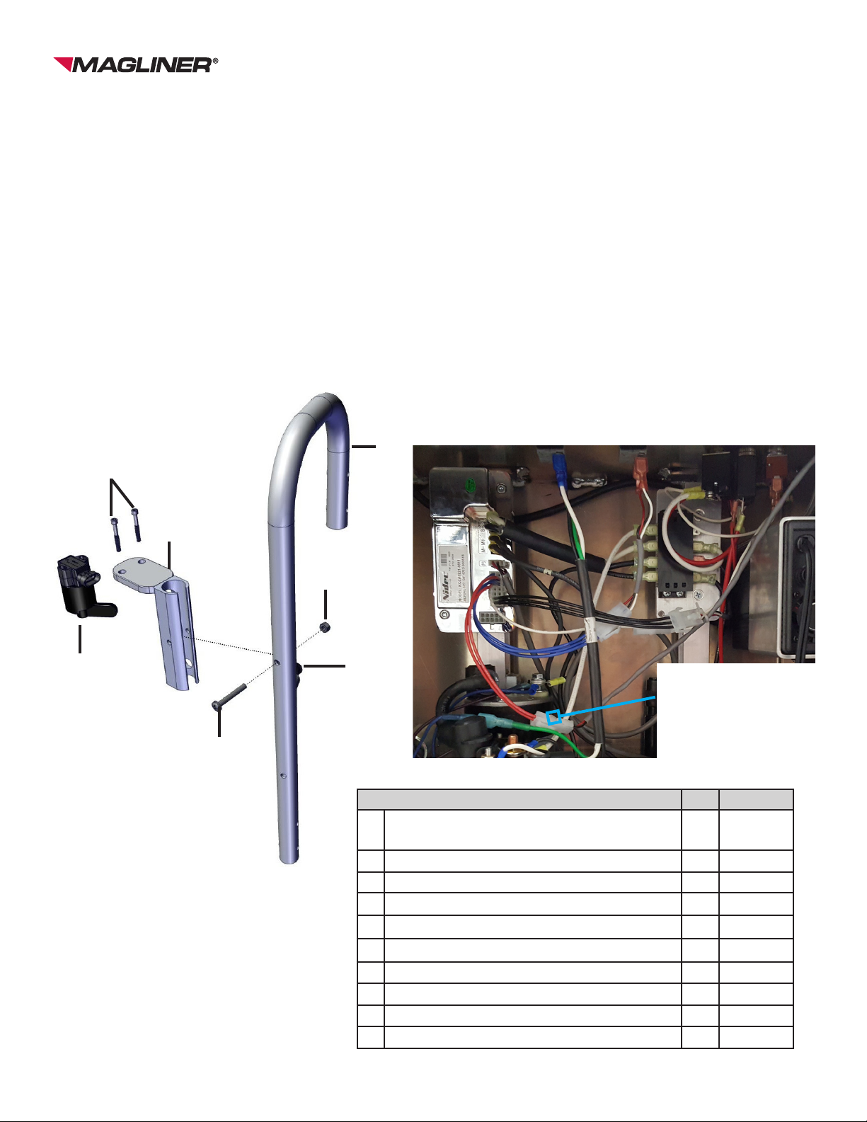
Vertical Loop Throttle Handle Removal ................................................................................................4
Vertical Loop Throttle Handle Replacement...................................................................................... 4-5
Replacing Throttle .................................................................................................................................6
Replacing Throttle Interlock Button .......................................................................................................7
Bulk Head Removal and Installation.................................................................................................8-11
Replacing Corner Post ........................................................................................................................12
Replacing Pallet Stops ........................................................................................................................12
Replacing Front Wheel........................................................................................................................13
Replacing Rear Swivel Caster.............................................................................................................13
Replacing Brushes ..............................................................................................................................14
Replacing Back Panel Latch................................................................................................................15
Removing Deck ...................................................................................................................................15
Removing Bottom Pans/Brace ............................................................................................................16
Replacing Containment Strap and Tongue..........................................................................................17
Replacing Battery Charger ..................................................................................................................18
Replacing Charger Cord................................................................................................................ 19-20
Replacing Power Switches..................................................................................................................21
Replacing Directional Switch...............................................................................................................21
Replacing Battery Meter......................................................................................................................22
Replacing Circuit Breaker....................................................................................................................23
Replacing Propulsion Controller..........................................................................................................24
Electrical Schematic ............................................................................................................................25
Replacing Motor Assembly ............................................................................................................ 26-27
Replacing Clutch Assembly ........................................................................................................... 28-29
Replacing Dierential Assembly .................................................................................................... 30-31
Changing Brake Caliper ................................................................................................................ 32-33
Changing Brake Pad ..................................................................................................................... 34-35
Changing Upper Brake Line .......................................................................................................... 36-37
Changing Lower Brake Line .......................................................................................................... 38-39
Replacing Brake Master Cylinder.................................................................................................. 40-41
Bleeding Brakes ............................................................................................................................ 42-43
Changing Hydraulic Pump............................................................................................................. 44-45
Changing Hydraulic Cylinder......................................................................................................... 46-47
Bleeding Hydraulic System............................................................................................................ 48-49
Replacing Brake Pawl ................................................................................................................... 50-51
Relocating Master Cylinder .................................................................................................................51
Replacing Center Wheel and Brake Disc ............................................................................................52
Troubleshooting............................................................................................................................. 53-54
Inspection / Maintenance Checklist................................................................................................ 55-62

1-800-MAGLINE (624-5463) Page 3 www.magliner.com
CooLift®
• Set of torx drivers
• #2, #3, #4 Phillips head screwdrivers
• 5/16”, 7/16”, two - 9/16”, 5/8”, 11/16”, 3/4”, 13/16” wrenches
• 6mm, two - 8mm, 10mm, 12mm, 13mm, 14mm, 17mm, two - 33mm,
35mm wrenches
• Four spacer blocks (4” x 4” x 24” wooden blocks)
• Isopropyl alcohol
• Vise on workbench
• Four vise-grip plier clamps (size 6r)
• Channel locks
• Rubber mallet
• Drift pin
• 1/2” socket w/extension and ratchet
• Needle nose pliers
• #1 at head screwdriver
• 4mm, 5mm Allen wrench
• 5/16”, 9/64” Allen wrench
• Tape measure
• Torque wrench
• Medium at head screwdriver
• Drip pan (cake pan will work)
• Absorbing material (kitty litter)
• DOT 3 or DOT 4 brake uid
• Hydraulic uid
• Shop towels
• Tube of clear silicone sealant
• Medium strength thread locker (blue)
• Flashlight
• Hydraulic thread sealant
• Utility knife
CooLift Toolkit

1-800-MAGLINE (624-5463) Page 4 www.magliner.com
CooLift®
VERTICAL LOOP THROTTLE HANDLE REMOVAL
TOOLS NEEDED:
TORX T30 DRIVER, #3 PHILLIPS SCREWDRIVER, 7/16” WRENCH, 7/64 ALLEN WRENCH
1) Turn o main power switch. Disconnect the batteries.
2) Unplug the throttle and throttle interlock button wiring from the main wiring harness (see pages
6-7).
3) Remove the two socket head screws at the lower part of the handle using two 7/16” wrenches.
4) Remove the two pan head machine screws at the top of the handle using #3 Phillips and one 7/16
wrench.
5) Remove the pan head machine screw holding the horizontal brace to the vertical loops.
6) Rotate the vertical loop handle toward center to clear the upper handle mounts.
7) The handle should be able to slide vertically through the end of the horizontal brace and removed.
This may take some eort and the end of the brace can be pried open slightly if necessary to ease
removal.
8) As the handle lifts, carefully guide and pull the throttle and throttle interlock cables through the
opening in the enclosure.
9) Once the cables have been pulled out of the enclosure the handle can be removed completely.
VERTICAL LOOP THROTTLE HANDLE REPLACEMENT
TOOLS NEEDED:
TORX T30 DRIVER, #3 PHILLIPS SCREWDRIVER, 7/16” WRENCH, , 7/64 ALLEN WRENCH
NOTE: Replacing a handle on the CooLift requires that the entire handle assembly rst must be
removed. See Vertical Loop Handle Removal for instructions.
1) Turn o main power switch. Disconnect the batteries.
2) With the entire handle assembly removed from the CooLift, take the new vertical loop handle
and slide the replacement handle into the horizontal brace, before it is lowered into place take
the throttle and interlock cables and feed them into the opening of the enclosure. Slide the
replacement handle into place and replace the screw; nger tighten only for now.
3) As the handle is lowered into place carefully pull the cables into the enclosure being sure not to
pinch them under the handle.
4) Once the handle is seated down rotate the top of the vertical loop handle into position.
5) Place the two screws into the top holes in the handles and then hand tighten it to the frame.
6) Place the screws the bottom holes located in the handles and hand tighten them to each of the
corner posts.
7) Place the remaining screw in the hole that secures the horizontal brace to the vertical loop handle,
carefully being sure not to pinch the cables in the handle, and tighten them using #3 Phillips
screwdriver and 7/16” wrench.
8) Tighten all previously hand tightened screws.
9) Plug the throttle cable and the interlock cable back into the main wiring harness going to the
controller (see pages 6-7).

1-800-MAGLINE (624-5463) Page 5 www.magliner.com
CooLift®
Item Qty. Part Number
AVertical loop handle - RH (includes handle, throttle mount
weldment, throttle interlock button and cable) 1 309667
B Vertical loop handle - LH 1 309568
C Horizontal brace 1 309560
D Pan head machine screw - 1/4”-20 x 1-1/2” long 6 80105
E Hex lock nut 1/4”-20 10 80675
F Pan head machine screw - 1/4”-20 x 1-3/4” long 2 80106
G Brake master cylinder 1 309218
H Throttle 1 309782
I Hex head cap screw - 1/4”-20 x 3/4” long 2 80005
A
H
G
F
E
D
B
I

1-800-MAGLINE (624-5463) Page 6 www.magliner.com
CooLift®
REPLACING THROTTLE
TOOLS NEEDED: 33mm WRENCHES; 3mm ALLEN WRENCH
1) Place the CooLift on a level ooring surface with the holding brake engaged.
2) Turn o main power switch. Remove back panel. Disconnect the batteries.
3) Unplug the throttle wiring harness from the main wiring harness that goes to the controller (see
below)
4) Using the Allen wrench remove the two screws from the top of the throttle mount.
5) Lift up on the tab and pull on the connector. Remove throttle cable.
6) Put new throttle on by pushing the cable into the new throttle until the plastic lock clicks.
7) Put two screws back into the top of the throttle with the lever towards the handle and snug up
the screws. Be careful not to tighten too much - over-torqueing may cause the lever to not move
freely. Tighten the screws and test to ensure that the throttle system is still moving freely.
8) Reconnect the throttle to the main wiring harness going to the controller and replace the back
panel.
A
Throttle mount screws
Unplug throttle from main
wiring harness HERE.
This part of the main wiring
harness consists of three
BLACK wires.
Item Qty. Part No.
A Throttle 1 309782

1-800-MAGLINE (624-5463) Page 7 www.magliner.com
CooLift®
REPLACING THROTTLE INTERLOCK BUTTON
TOOLS NEEDED: #3 PHILLIPS SCREWDRIVER, FLAT HEAD SCREWDRIVER, 7/16” WRENCH,
NEEDLE NOSE PLIERS
Item Qty. Part No.
AVertical handle assembly with throttle (includes
items below): 1 309667
B Handle 1 309627
C Mounting weldment for throttle 1 309765
D Pan head machine screw - 1/4”-20 x 1-3/4” long 1 80106
E Hex lock nut - 1/4”-20 1 80675
F Throttle interlock button 1 62042
G Cable for throttle interlock (in handle, not shown) 1 62057
H Throttle 1 309782
I Throttle cable (in handle, not shown) 1 62073
J Socket head cap screw - #10-24 x 1-1/2” long 2 80145
1) Place the CooLift on a level ooring surface with the holding brake engaged.
2) Turn o main power switch. Remove back panel. Disconnect the batteries.
3) Unplug throttle interlock button wiring harness from the main wiring harness that goes to the
controller (see below).
4) Carefully pull old interlock button out of the handle being careful not to damage the wiring. Use
the at head screwdriver if necessary.
5) Remove wires from button.
6) Attach wires to the new button (quick connect tabs) by aligning the connector with tab and push
on. It does not matter which wire goes on which tab.
7) Carefully insert button into the hole in handle, and press in place.
8) Plug throttle interlock button wiring harness into the main wiring harness as shown below.
B
C
D
E
FH
J
Unplug throttle interlock
from main wiring harness
HERE.
This part of the main wiring
harness consists of two
RED wires.

1-800-MAGLINE (624-5463) Page 8 www.magliner.com
CooLift®
CPA43 BULK HEAD REMOVAL
TOOLS NEEDED:
7/16” WRENCH, 1/2” WRENCH, #3 PHILLIPS SCREWDRIVER, #4 PHILLIPS SCREWDRIVER
SPACER BLOCK (4” x 4” x 24” WOODEN BLOCK)
Note: It is important to keep the CooLift upright at all times.
1) Place the CooLift on a level ooring surface with the holding brake engaged.
2) Raise the deck to the highest position.
3) Place a spacer block between the deck and the base of the cart.
4) Turn o main power switch.
5) Remove the two screws (I) that attach the bulk head (A) to the base plate using the #4 Phillips
screwdriver and the 1/2” wrench.
6) Take out the four screws (G) that attach the bulk head saddle plate (B) and the load retaining strap
assembly and spacer (C, D) to the bulk head and the main cart using the #3 Phillips screwdriver
and the 7/16” wrench.
NOTE: If the bulk head is going to be reinstalled after servicing, only the two screws (G)
anchored to the main cart and the saddle plate need to be removed. If the bulk head is
taken o and the CooLift will be used in the 53” pallet conguration, a new saddle plate
(309151) will need to be installed.
7) Lift and remove the saddle plate. Then lift and remove the bulk head frame to disengage from the
base plate.
CPA43 BULK HEAD INSTALLATION
TOOLS NEEDED:
7/16” WRENCH, 1/2” WRENCH, #3 PHILLIPS SCREWDRIVER, #4 PHILLIPS SCREWDRIVER
SPACER BLOCK (4” x 4” x 24” WOODEN BLOCK)
Note: It is important to keep the CooLift upright at all times.
1) Place the CooLift on a level ooring surface with the holding brake engaged.
2) Raise the deck to the highest position.
3) Insert a spacer block between the deck and the base of the cart.
4) Turn o main power switch.
5) Slide the bulk head (A) into position on the bulk head mounts located on the base plate.
6) Place the bulk head saddle plate (B) into position with the containment strap assembly and strap
spacer (C, D) above it and attach using the four screws (G) and lock nuts (H) and nger tighten.
7) Attach the bulk head to the mounts on the base plate using the two screws (I) and securely tighten
them to the lock nuts (J) using the #4 Phillips screwdriver and the 1/2” wrench.
8) Securely tighten the four screws (G) in the bulk head saddle plate (B) using the #3 Phillips
screwdriver and the 7/16” wrench.

1-800-MAGLINE (624-5463) Page 9 www.magliner.com
CooLift®
Item Qty. for
CTA43
Qty. for
CTA53 Part Number
A Bulk head for CTA43 1 -- 309790
B Bulk head saddle plate for CTA43 1 -- 309341
C Containment strap 1 1 309152
D Containment strap mounting spacer 1 1 309150
E Screw - 3/8”-16 x 1-1/2” long 1 1 79988
F Hex lock nut - 3/8”-16 1 1 80603
G Screw - 1/4”-20 x 2-3/4” long 4 2 80111
H Hex lock nut - 1/4”-20 4 2 80675
I Screw - 5/16”-18 x 1” long 2 -- 80313
J Hex lock nut - 5/16”-18 2 -- 80676
Completed assembly
E
C
D
B
F
G
A
H
J
I

1-800-MAGLINE (624-5463) Page 10 www.magliner.com
CooLift®
CPA48 BULK HEAD REMOVAL
TOOLS NEEDED:
7/16” WRENCH, 1/2” SOCKET END WRENCH, #3 PHILLIPS SCREWDRIVER, TWO 9/16”
WRENCHES, SPACER BLOCK (4” x 4” x 24” WOODEN BLOCK)
Note: It is important to keep the CooLift upright at all times.
1) Place the CooLift on a level ooring surface with the holding brake engaged.
2) Raise the deck to the highest position.
3) Place a spacer block between the deck and the base of the cart.
4) Turn o main power switch.
5) Remove the two screws (I) and lock nuts (F) that attach the bulk head (A) to the base plate using
the 1/2” socket end wrench.
6) Take out the four screws (G) and lock nuts (H) that attach the bulk head saddle plate (B) and the
containment strap assembly and spacer (C, D) to the bulk head and the main cart using the #3
Phillips screwdriver and the 7/16” wrench.
NOTE: If the bulk head is going to be reinstalled after servicing, only the two screws (G)
anchored to the main cart and the saddle plate need to be removed. If the bulk head is
taken o and the CooLift will be used in the 53” pallet conguration, a new saddle plate
(309151) will need to be installed.
7) Lift and remove the saddle plate. Then lift and remove the bulk head frame to disengage from the
base plate.
CPA48 BULK HEAD INSTALLATION
TOOLS NEEDED:
7/16” WRENCH, 1/2” SOCKET END WRENCH, #3 PHILLIPS SCREWDRIVER, TWO 9/16”
WRENCHES, SPACER BLOCK (4” x 4” x 24” WOODEN BLOCK)
Note: It is important to keep the CooLift upright at all times.
1) Place the CooLift on a level ooring surface with the holding brake engaged.
2) Turn o main power switch.
3) Slide the bulk head (A) into position on the base plate in the location shown in Figure 2.
4) Fasten in place using the two screws (I) and lock nuts (F) and nger tighten (the screw heads will
be on top of the base plate and the lock nuts underneath).
5) Place the bulk head saddle plate (B) into position and attach using the four 1/4”-20 x 2-3/4” long
screws (G) and 1/4”-20 lock nuts (H) and nger tighten.
6) Place the containment strap mounting spacer (D) onto the bulk head saddle plate and then place
the containment strap assembly (C) onto the mounting spacer. Insert one 3/8”-16 x 1-1/2” long
screw (E) and 3/8”-16 lock nut (F) and securely tighten using the two 9/16” wrenches.
7) Once all items are in place, securely tighten the hardware for the bulk head saddle plate and for
the hardware connecting the bulk head to the base plate

1-800-MAGLINE (624-5463) Page 11 www.magliner.com
CooLift®
Figure 2
A
B
D
GC
F
E
I
H
Item Qty. for
CTA48
Qty. for
CTA53 Part Number
A Bulk head for CTA48 1 -- 309791
B Bulk head saddle plate for CTA48 1 -- 309341
C Containment strap 1 1 309152
D Containment strap mounting spacer 1 1 309150
E Screw - 3/8”-16 x 1-1/2” long 1 1 79988
F Hex lock nut - 3/8”-16 3 1 80603
G Screw - 1/4”-20 x 2-3/4” long 4 2 80111
H Hex lock nut - 1/4”-20 4 2 80675
I Screw - 3/8”-16 x 1-1/4” long 2 -- 80026

1-800-MAGLINE (624-5463) Page 12 www.magliner.com
CooLift®
B
A
C
B
309206
REPLACING PALLET STOPS - CPA43 AND CPA48
TOOLS NEEDED:
1/2” SOCKET END WRENCH
Note: It is important to keep the CooLift upright at all times.
1) Place the CooLift on a level ooring surface with the holding brake engaged.
2) Turn o main power switch.
3) Remove and discard old pallet stop.
4) Locate the front hole of the pallet stop as shown in Figure 1 and insert the screw (A).
5) Locate the front hole on the deck (for CTA43 models) or the back hole on the deck (for CTA48 models). Insert the
pallet stop (B) and the screw (A) as shown. Fasten with the 5/16”-18 lock nut (C) using the 1/2” socket end wrench on
the lock nut on the inside of the deck frame channel.
6) Repeat process for the opposite side. Item Qty. Part No.
A Screw - 5/16”-18 x 1-1/4” long 2 80012
BPallet stop - CPA43 models 1 309826
Pallet stop - CPA48 models 1 309206
C Hex lock nut - 5/16”-18 2 80676
Quantities listed are for both sides of the CooLift
CTA48
CTA43
REPLACING CORNER POST
TOOLS NEEDED:
7/16” WRENCH, 1/2” WRENCH, #3 PHILLIPS HEAD SCREWDRIVER
Note: It is important to keep the CooLift upright at all times.
1) Place the CooLift on a level ooring surface with the holding brake engaged.
2) Turn o main power switch.
3) Remove the battery box (see Replacing Battery Box for proper removal).
4) Remove the ve screws (C, E) and hex nuts (A, D) and the corner post (B).
5) Position the new corner post in place and secure with the previously removed screws and nuts.
6) Replace the battery box (see Replacing Battery Box for proper installment).
Item Qty. Part Number
A Hex lock nut - 1/4”-20 3 80675
B Corner post assembly 1 309108
C Screw - 1/4”-20 x 1-1/2” long 3 80105
D Hex lock nut - 5/16”-18 2 80676
E Screw - 5/16”-18 x 1-1/2” long 2 80115
Quantities listed are for one side of the CooLift
C, A
B
E, D
309826

1-800-MAGLINE (624-5463) Page 13 www.magliner.com
CooLift®
REPLACING FRONT WHEEL
TOOLS NEEDED: PLIERS
Caution: Remove and replace only one roller at a time.
1) With the cart sitting on a level ooring surface and the holding brake engaged, remove the cotter pin, washers and
roller.
2) Replace with new roller and washers as shown below. Install cotter pin and bend the ends to hold in place.
A
B
C
BD
Item Qty. Part
Number
A Cotter pin - 1/8” x 1-1/2” long 1 81078
B Washer 2 80723
C Front wheel 1 130014
D Front axle - 13” long 1 309844
Quantities listed are for each front roller
REPLACING REAR SWIVEL CASTER
TOOLS NEEDED: TWO 9/16” WRENCHES
Caution: Remove and replace only one caster at a time.
1) With the cart sitting on a level ooring surface, the holding brake engaged and the rear access panel removed,
remove the battery(ies).
2) Loosen the three screws that hold the caster mount to the base of the cart using the pair of 9/16” wrenches.
3) The entire rear swivel caster assembly can now be lowered and slid out of position.
4) Position the replacement rear swivel caster in place and insert the three screws through the base of the cart and
fasten with lock nuts against the swivel caster mount using the pair of 9/16” wrenches.
5) Replace back access panel.
A
C
Item Qty. Part
Number
AHex head cap screw - 3/8”-16
x 1-1/4” long 3 80026
BHex lock nut ange - 3/8”-16 3 80624
CCaster assembly - 6” x 2”
swivel grey at tread 1 130066
Quantities listed are for each rear swivel caster
B

1-800-MAGLINE (624-5463) Page 14 www.magliner.com
CooLift®
REPLACING BRUSHES
TOOLS NEEDED:
FLAT HEAD SCREWDRIVER, #3 PHILLIPS SCREWDRIVER, PAIR OF PLIERS
Note: It is important to keep the CooLift upright at all times.
1) Place the CooLift on a level ooring surface.
2) Engage the holding brake.
3) Turn o main power switch.
4) Remove the back access panel from the cart.
5) Insert the at head screwdriver into end of the slotted frame that holds the brush section and bend
the end of the slot open enough to allow the old sections to slide out (A, B).
6) Remove the old brush sections using the pliers to grab them and slide them out of the slots.
7) Slide in the new brush sections (A, B) into place.
8) Using the pliers, re-crimp the ends of the slots to enable the brush sections to remain in place.
9) Place the back access panel back into position and secure with the latches.
Item Qty Part Number
A Yoke brush 1 309257
B Back panel brush 1 309259
B
A

1-800-MAGLINE (624-5463) Page 15 www.magliner.com
CooLift®
D
C
A
B
REMOVING THE DECK
TOOLS NEEDED: #3 PHILLIPS SCREWDRIVER, FLAT HEAD SCREWDRIVER, 7/16” WRENCH
1) Place the CooLift on a level ooring surface with the holding brake engaged.
2) Raise the deck to the highest position.
3) Turn o main power switch. Disconnect batteries.
4) Remove the two screws connecting the deck to the hydraulic cylinders.
5) Remove the four screws and lock nuts connecting the back of the deck to the yokes.
6) Pull deck forward out of the yokes; use light blows with a soft mallet if needed.
7) Reconnect batteries.
Item Qty. Part Number
A Deck 1 309825
B Flat head machine screw - 1/4” -20 x 2” long 4 80224
C Hex lock nut - 1/4”-20 4 80675
D Slotted truss head screw - 3/8”-16 x 1/2” long 2 80286
REPLACING BACK PANEL LATCH
TOOLS NEEDED: #3 PHILLIPS SCREWDRIVER
1) Remove back panel from the unit. Remove the damaged latch from back panel.
2) Insert new latch in the orientation shown below. Position the mounting bracket on the opposite side for the panel.
3) Install enclosed screw through the bracket and latch; tighten.
4) Adjust the clamp screw:
• Loosen jam nut.
• Adjust the screw in or out until latch will rmly secure door in place.
• Tighten jam nut.
Item Qty. Part
Number
ABack access panel latch (includes
items below, not sold separately) 1 309573
B Screw 1 -
C Mounting bracket 1 -
D Latch assembly 1 -
NOTE - full back panel assembly replacement part
number is 309842.
D
A
C
B

1-800-MAGLINE (624-5463) Page 16 www.magliner.com
CooLift®
REMOVING BOTTOM PANS/BRACE
TOOLS NEEDED: 1/2” WRENCH, T30 TORX SCREWDRIVER, BLUE THREAD LOCKER
Note: It is important to keep the CooLift upright at all times.
1) Place the CooLift on a level ooring surface with the holding brake engaged. For some
procedures, the CooLift can be placed safely on sturdy surfaces that raise the CooLift at least 12”
o the ground.
2) Remove the front and rear pans using the T30 Torx screwdriver.
3) Remove the center brace using 1/2” wrench.
4) When reinstalling these items to the CooLift, coat the threads of all fasteners with blue thread
locker.
Item Qty.
Part
Number
A Front pan 1 309821
B Center brace 1 309614
C Rear pan 1 309822
D Pan head thread forming screw - 1/4”-20 x 3/4” long 14 80308
EHex head cap screw with thread locking patch -
5/16”-18 x 3/4” long 4 80010

1-800-MAGLINE (624-5463) Page 17 www.magliner.com
CooLift®
REPLACING CONTAINMENT STRAP TONGUE
TOOLS NEEDED: #2 PHILLIPS HEAD SCREWDRIVER AND 3/8” WRENCH
Note: It is important to keep the CooLift upright at all times.
1) Place the CooLift on a level ooring surface with the holding brake engaged.
2) Remove the containment strap tongue (I) by taking out the mounting screw (J) and lock nut (H)
using the #2 Phillips head screwdriver and the 3/8” wrench.
3) Position the new containment strap tongue (J) so the tab with the rectangle-shaped hole is facing
outward from front of cart and the holes are lined up with the holes on the mounting block and
secure it with the previously removed screw (J) and lock nut (H), allowing the tongue to rotate
freely.
REPLACING CONTAINMENT STRAP
TOOLS NEEDED: TWO 1/2” WRENCHES
Note: It is important to keep the CooLift upright at all times.
1) Place the CooLift on a level ooring surface with the holding brake engaged.
2) Remove the containment strap assembly (A) by taking out the mounting screw (C) and lock nut
(D) using the two wrenches.
3) Position the new containment strap assembly (A) such that the tab sits on top of the mounting
spacer (B). Insert the previously removed screw (C) and tighten the lock nut (D) using the two
wrenches.
H
J
I
Front
Underside
View
Item Qty.
Part
Number
A Containment strap 1 309152
BContainment strap mounting
spacer 1 309150
C Screw - 3/8”-16 x 1-1/2” long 1 79988
D Hex lock nut - 3/8”-16 1 80603
Item Qty. Part
Number
HHex lock nut w/ nylon insert -
#10-24 UNC 1 80683
I Containment strap tongue 1 309133
J Screw - #10-24 x 2-1/2” long 1 80004
A
B
C
D

1-800-MAGLINE (624-5463) Page 18 www.magliner.com
CooLift®
REPLACING BATTERY CHARGER
TOOLS NEEDED:
#2 PHILLIPS HEAD SCREWDRIVER
Note: It is important to keep the CooLift upright at all times.
1) Place the CooLift on a level ooring surface.
2) Engage the holding brake.
3) Turn o main power switch. Remove the back access panel. Unplug the charger connect cable (A).
4) Disconnect the batteries from the existing charger (B).
5) Unplug the output cord from the charger.
6) Remove the two #10 x 3/4” long screws (C) from the U-shaped mounting bracket (D) using the #2 Phillips
head screwdriver, taking care to keep the charger and bracket from dropping once the screws are
removed.
7) Unplug the input cord from the charger. Remove the old battery charger from the mounting bracket.
8) Place the charger ON/OFF switch on the ON position on the new charger (see Figure 3). Plug the input
cord in the new charger.
9) Center the charger in the mounting bracket. NOTE: The charger ON/OFF switch should be oriented
towards the back wall.
10) Carefully place the charger and mounting bracket against the RH inside enclosure wall,
centering the charger within the mounting bracket. Reinstall the 3/4” long screws into the
mounting bracket.
11) Plug the charger output cord into the charger.
12) Connect the charger output cord to the batteries.
13) Test the charger by plugging the charger cord into a grounded 115v outlet and check the
charger indicator lights.
Troubleshooting tips if no light turns on:
- Conrm 115v outlet is operable.
- Conrm the charger ON/OFF switch is in the ON position.
- Conrm the input power cord is securely plugged into the charger receptacle.
14) Replace the back access panel.
Item Description Qty. Part #
ACharger connect cable 1 62046
BAC charger for 24v battery 1 63004A
CPan head machine screw - #10-32 x
3/4” long 2 80121
D Charger mounting bracket 1 309207
B
C
Figure 3
ON/OFF switch
D
B
A

1-800-MAGLINE (624-5463) Page 19 www.magliner.com
CooLift®
1) Turn o main power switch. Unplug the charger connect cable.
2) Loosen the cord grip using slip joint pliers. Remove the jam nut on the cord grip and pull out the
rubber insert to allow the cord to move freely within the tting.
3) Remove the male end of the plug from the existing cord using the #2 Phillips head screwdriver.
4) Remove the back access panel from the cart by removing the mounting screws using the #3
Phillips head screwdriver.
5) Unplug the existing cord from the charger socket and remove from the enclosure.
5) Cord installation:
a. Assembling into the enclosure
i. Remove the male end of the plug (D) from the replacement cord using the #2 Phillips head
screwdriver.
ii. Slip the cord (C) from the inside of the enclosure up through the hole in the enclosure and
through the cord grip (A) and lock nut (B).
iii. Remove excess cord from the inside of the enclosure until a length of 6-1/2” to 7” is left.
iv. Tighten the jam nut.
b. Assemble cord plug (see wiring part diagram, next page)
i. Shorten the three exposed wires to 1-1/8”long, then strip each wire back 9/16” from the end.
ii. Insert the cord end through the cord plug base, then insert and secure the three wires to the
plug terminals:
a. Green wire to center terminal
b. Black or blue wire to terminal with black or brass screw terminal
c. White or brown wire to silver screw terminal
Note: Review wiring part diagram to conrm correct wire-terminal connection.
iii. Reassemble cord plug and securely tighten cord grip clamp.
6) Test the charger by plugging the charger cord into a grounded 115v outlet and check the charger indicator
lights.
Troubleshooting tips if no light turns on:
- Conrm 115v outlet is operable.
- Conrm the charger ON/OFF switch is in the ON position.
- Conrm the input power cord is securely plugged into the charger receptacle.
7) Replace and secure the enclosure panel using the #3 Phillips head screwdriver.
8) To store the charger cord, coil the charger cord around the two brackets, interlacing the cord plug within
the coiled cord loops to secure it. Figure 2 shows the completed bracket assembly with the cord properly
secured to the brackets.
REPLACING CHARGER CORD
TOOLS NEEDED:
SLIP JOINT PLIERS
#2 PHILLIPS HEAD SCREWDRIVER
#3 PHILLIPS HEAD SCREWDRIVER
18 AWG WIRE STRIPPER/CUTTER
Note: It is important to keep the CooLift upright at all times.

1-800-MAGLINE (624-5463) Page 20 www.magliner.com
CooLift®
Item Description Qty. Part #
A Cord grip - PG-16 1 309122
B Hex lock nut - PG-16 1 309123
C Electrical cord 8’ long with C13 connector on one end 1 64020
D Plug - 15A rated 5-15p three-prong cord plug 1 61053
Figure 2
A
Wiring Part Diagram
Jam nut
Cord grip
(A)
Figure 1
Hex lock nut
(B)
D
C
4 % Dn _
9
•
=1
BSS OR BLACK SCREW
This manual suits for next models
2
Table of contents
Other Magliner Outdoor Cart manuals

Magliner
Magliner 4-WHEEL ARISTOCART User manual

Magliner
Magliner GEMINI XL User manual

Magliner
Magliner BS-MLS User manual

Magliner
Magliner Caddy Cart User manual

Magliner
Magliner MGA81G16-3 User manual

Magliner
Magliner Powered Stair Climber Operating instructions

Magliner
Magliner HD Series User manual

Magliner
Magliner Hand Truck User manual

Magliner
Magliner HMK111AA15 User manual