manuals.online logo
Brands
  1. Home
  2. •
  3. Brands
  4. •
  5. Magnaflux
  6. •
  7. Diagnostic Equipment
  8. •
  9. Magnaflux EV6000 User manual

Magnaflux EV6000 User manual

© 2016 Magnaflux Page 1 Magnaflux-SRVC-TS032
Issued: Mar 2016
Rev. 1
EV-6000 LED UV Lamp Repair Technique Sheet
© 2016 Magnaflux Page 2 Magnaflux-SRVC-TS032
Issued: Mar 2016
Rev. 1
Repairs that are possible on the EV-6000 (Refer to Page 5 in the EV-6000
Manual for exact part location and part numbers)
A. Replacement of Rear Cover Gasket (Index #10)
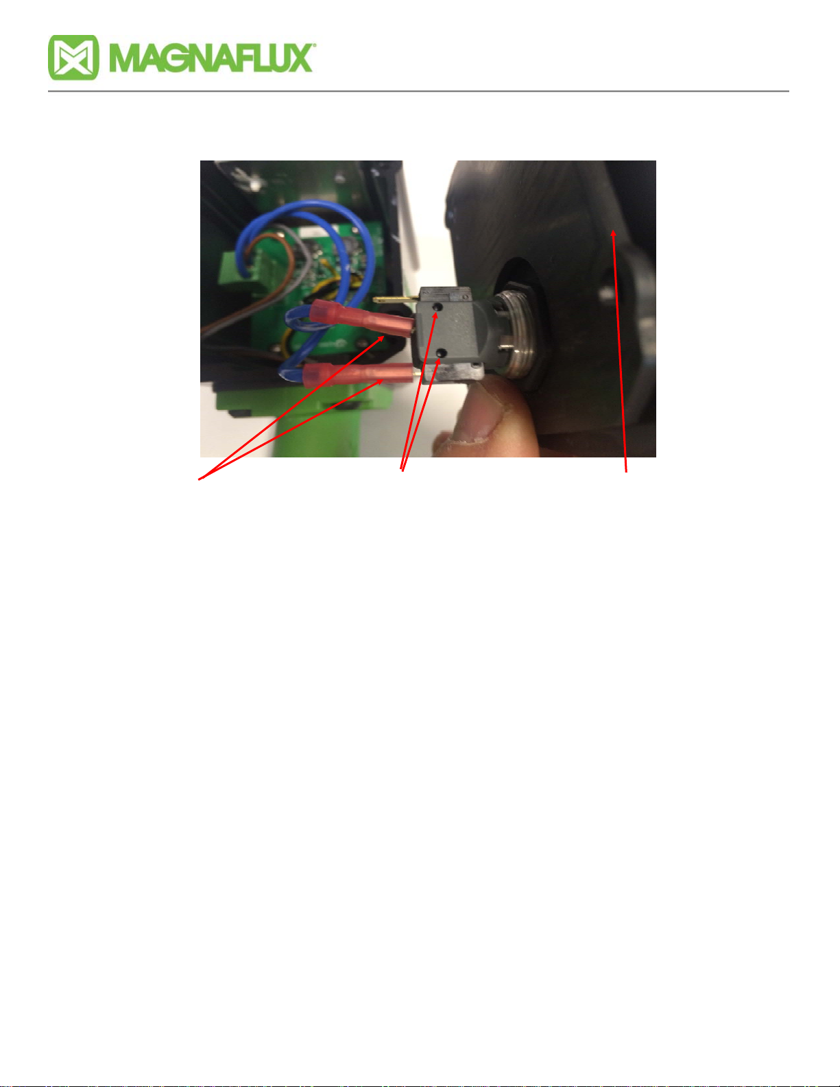
B. Replacement of “On/Off” Power Switch (Index #12)
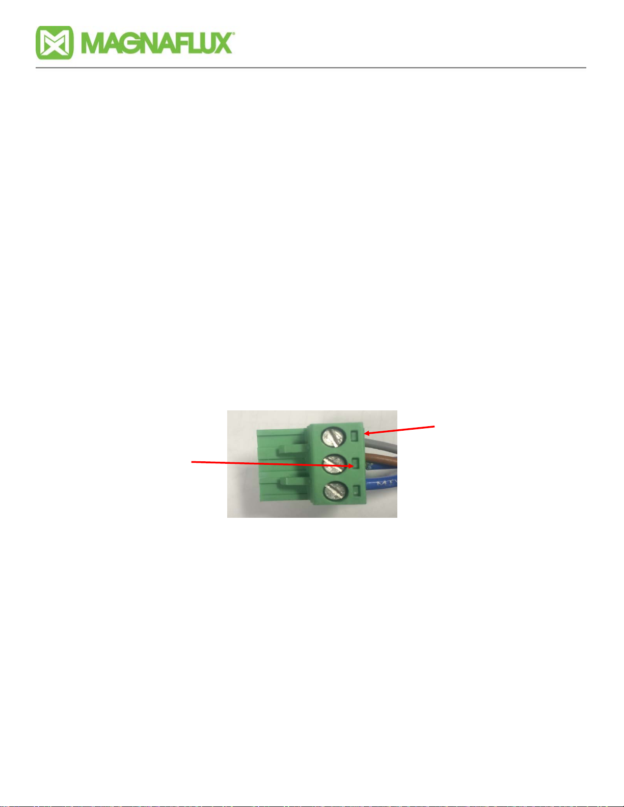
C. Testing and Replacing EV6000 Power Cable (Index #17)
D. Testing and Replacing EV6000 Power Supply (Not shown in manual)
E. Replacement of EV6000 LED Assembly (Index #7) — Note: Only complete replacement
of the EV6000 LED Assembly is authorized. No repairs are possible and the optic lens
are not field replaceable.
NOTE #1: Replacement of the UV filter, filter gasket and front cover gasket (Index #’s 3, 4
and 6)— Instructions are located on page 4 of the EV6000 manual.
NOTE #2: Anytime the rear cover is removed, the rear cover gasket should be inspected for
any signs of degradation, deformation, or tears. If anything unusual is observed, replace
the gasket.
Tools needed to perform work:
1. 2.5 mm Hex Key Wrench (Used for LED Array Assembly)
2. 3 mm Hex Key Wrench (Used for removal of front and rear covers
3. 22 mm wrench or crescent wrench (only needed if replacing “On/Off” Power Switch)
4. Needle nose pliers (only needed if replacing “On/Off” Power Switch)
5. AC/DC voltmeter — Capable of reading 115/230 volts AC and 24 volts DC
Additional items needed if replacing the EV6000 LED Assembly:
1. Static control mat with grounding protection
2. Techspray Silicone Free Heat Sink Compound 1978-DP (4 oz. tube). Please note that
other silicone free heat sink compounds have not been tested for compatibility with the
EV6000 LED Array Assembly and therefore are not authorized to be used.
© 2016 Magnaflux Page 3 Magnaflux-SRVC-TS032
Issued: Mar 2016
Rev. 1
Replacement Procedures
Prior to starting any repairs — the EV6000 should be disconnected from
the power supply.
A. Replacement of Rear Cover Gasket
1. Using the 3 mm hex key wrench, loosen and remove the 4 shoulder bolts that hold on
rear cover shown in Figure 1.
2. Once the 4 shoulder bolts are removed, carefully lift the rear cover off of the EV-6000.
The rear cover gasket may or may not come off with the rear cover.
3. In order to replace the rear cover gasket, you will have to remove the electrical part of
the “On/Off” switch called the micro-switch This is easy to do — but it is also easy to
break the switch. Refer to Figure 2 on the following page and follow the instructions to re-
move the operational part of the “On/Off” switch.
Figure 1
Shoulder BoltsShoulder Bolts
© 2016 Magnaflux Page 4 Magnaflux-SRVC-TS032
Issued: Mar 2016
Rev. 1
Figure 2
Guide Pins that hold the opera-
tional part of the “On/Off” switch
in place. There is a set on each
side of the gray holder.
Rear cover gasket is
on the rear cover
Wires on switch are
on the bottom two
terminals
4. Grasp the micro-switch portion of the “On/Off Switch” with your forefinger & thumb and tilt
the switch in the gray holder until the two guide pins on the switch come out of the guide
pin holes of the gray holder. Then tilt the switch in the opposite direction so that the other
two guide pins on the switch comes out of the guide pin holes on the opposite side.
NOTE: You may have to rock the switch back and forth to free the switch.
5. Once switch is removed, you can now easily replace the rear cover gasket.
6. Once rear cover gasket is replaced, insert the micro-switch back into the gray switch hold-
er, ensuring that the two wires on the micro-switch are in the same configuration (closest
to the bottom of the EV6000). You will know when the micro-switch is in it’s proper posi-
tion as the guide pins on each side of the switch will lock into the guide pin holes on the
gray micro-switch holder.
7. Place rear cover onto EV6000 and insert the 4 shoulder bolts removed in step A.1 using
the 3 mm hex key wrench until they stop (little or no pressure required to do this. The
tighten the 4 shoulder bolts an additional 1/8—1/4 turn.
© 2016 Magnaflux Page 5 Magnaflux-SRVC-TS032
Issued: Mar 2016
Rev. 1
B. Replacement of “On/Off” Power Switch
1. Perform steps A.1 through A.4 “Replacement of Rear Cover Gasket
2. Using 22 mm wrench or small crescent wrench, remove the nut that holds on the mechani-
cal portion of the “On/Off” Power Switch as shown in Figure 3. Note: Pink Post-It note is
shown in Figure 3 so that the nut can be seen.
3. Once nut is removed, the mechanical portion of the “On/Off Switch” will slide out easily.
4, Insert new mechanical portion into hole with the gray micro-switch holder aligned so that
the sides as shown in Figure 3. Screw on nut by hand until tight. Then tighten nut with
wrench an additional 1/8”.
5. Using needle nose pliers, remove the electrical leads from the micro-switch portion of the
“On/Off Switch” as shown in Figure 4. You will have to move the connector back and forth
in order to remove the lead from the terminal on the micro-switch.
Figure 3
Nut that holds on me-
chanical portion of
“On/Off” Switch.
Figure 4
© 2016 Magnaflux Page 6 Magnaflux-SRVC-TS032
Issued: Mar 2016
Rev. 1
6. Reattach leads to the new micro-switch. Ensure leads are attached to the “C” terminal on
the bottom and the “NO” terminal located next to it as shown in Figure 5.
7. Ensure rear cover gasket is place on rear cover (if removed earlier) and insert the micro-
switch back into the gray switch holder, ensuring that the two wires on the micro-switch
are in the same configuration (closest to the bottom of the EV-6000). You will know when
the micro-switch is in it’s proper position as the guide pins on each side of the switch will
lock into the guide pin holes on the gray micro-switch holder. Refer to Figure 2 on page 4
for proper installation.
8. Place rear cover onto EV6000 and insert the 4 shoulder bolts using the 3mm hex key
wrench until they stop (little to no pressure required). Then tighten the 4 shoulder bolts an
additional 1/8—1/4 turn.
Figure 5
“C” Terminal “NO” Terminal
© 2016 Magnaflux Page 7 Magnaflux-SRVC-TS032
Issued: Mar 2016
Rev. 1
C. Testing and Replacing of EV6000 Power Supply
Note: No repairs of the EV6000 Power Supply are authorized other than replacing the Power
Supply or associated cord that goes from the Power Supply to the EV6000 LED light.
1. To verify that the EV-6000 Power Supply is functioning correctly:
a. Set voltmeter to DC volts and adjust the range so that the voltmeter can read 24
volts DC.
b. You will need to use two pieces of 18 GA or 20 GA wire. Trim both pieces so that
you have bare wire exposed at both ends (Approx. 1/4”). Ensure that the exposed
portions are twisted together tightly.
c. Refer to Figure 6 and Figure 7. Insert the two pieces of wire into the connector as
shown in Figure 6 and 7. Then hook up leads of voltmeter as shown in Figure 6.
d. Plug the EV6000 power supply into a 115 volt outlet.
e. DC voltage coming out of Power Supply should be 24 volts DC (+/-1 volt). If the
voltmeter reads “0” volts — Ensure that your 115 volts is energized. If the 115 volt AC
is energized — Then you will need to replace the power supply. The Magnaflux Part #
for the power supply (115 volt and 230 volt) is 625877.
Figure 6 Figure 7
Notch
“+” (POS)
”-” (NEG)
“+” (POS)
”-” (NEG)
© 2016 Magnaflux Page 8 Magnaflux-SRVC-TS032
Issued: Mar 2016
Rev. 1
D. Testing and Replacing EV 6000 Power Cable (Cable that goes from power
supply to EV6000 Light)
1. Prior to replacing the power cable, a simple test can be performed to verify if the cable is
bad or not.
a. Perform EV6000 Power Supply Test as described in Section C and verify that
EV6000 Power Supply is functioning correctly.
b. Remove the rear cover and rear cover gasket of the EV6000 and rear cover gasket
per A.1 and A.2 of this procedure.
c. Unplug the Power Cable Connector Plug (shown in Figure 8) so that you can gain
access to test points on the plug.
d. Set the voltmeter to DC volts and the range so that it will read 24 volts. Place the
“+” lead on the middle screw terminal (brown wire) and the “-” lead on the first screw
terminal (gray wire) as shown in Figure 9.
e. Plug in the EV6000 power supply and observe the voltage. If 24 volts (+/- 1 volt) is
not observed and the EV600 Power Supply has been tested and working satisfactorily,
then the EV6000 Power Cable will need to be replaced.
Figure 8
Power Cable
Connector Plug
Figure 9
“+” (POS)
”-” (NEG)
Figure 8a
NOTE: Green and Yellow wire (may be different color) has terminal on it and is at-
tached to bolt that secures LED array. The other end of the wire is connected to
earth ground in the power supply.
© 2016 Magnaflux Page 9 Magnaflux-SRVC-TS032
Issued: Mar 2016
Rev. 1
2. To replace the EV6000 Power Cable:
a. Unplug the EV6000 Power Supply
b. Disconnect the EV6000 Power Cable from the EV6000 Power Supply
c. Refer to Figure 9, using a small flat tip screwdriver, loosen the terminals that hold
the gray wire (“-”) and brown wire (“+”) and then remove the wire from the terminals.
On the middle terminal (“+”), there is also a blue wire which you will reattach when the
new EV6000 Power Cable is installed.
d. Using either a 15 MM open-end wrench or crescent wrench -Loosen and remove
the strain relief nut shown in Figure 10. Once the nut is completely loose — you can
back off the strain relief nut onto the cord.
NOTE: It may take a little bit of “force” to loosen the strain relief nut, but that is okay.
e. Using a 3 mm hex key wrench remove the 4 bolts that hold on the EV-6000 handle
and handle gasket as shown in Figure 11. Then remove the handle and gasket.
Figure 11
Strain Relief Nut
Figure 10
Handle Mounting
Bolts Handle Mounting
Bolts
© 2016 Magnaflux Page 10 Magnaflux-SRVC-TS032
Issued: Mar 2016
Rev. 1
f. Pull the existing EV6000 Power Cable back through the EV6000 handle. Remove
the strain relief nut so that it can be reused on the new EV6000 Power Cord.
g. Slide the strain relief nut over the wire end of the new EV6000 Power Cable.
h. Insert the new EV6000 Power Cable into the EV6000 handle. Push the cable up
through the handle until the insulated part of the cable is at the top of the handle.
i. Slide the strain relief nut up the EV6000 Power Cable and attach it to the fitting that
is installed on the EV6000 handle. Tighten nut by hand until it stops and then use the
15 mm wrench to tight nut and additional 1/8 to 1/4 of a turn. NOTE: Over tightening
of the nut will cause the strain relief clamp to cut through the insulation of the cable.
j. Ensure the gasket is in place on top of the EV-6000 handle and reinstall the EV6000
handle with the mounting bolts that were removed in step 2.e. Use the 3 mm hex key
to screw in the bolts until they stop and then tighten an additional 1/8—1/4 of a turn..
k. Connect the gray wire from the EV6000 Power Cable to the first terminal of Power
Cable Connector Plug. Then connect the brown wire and the blue wire (that was
disconnected when the old EV6000 Power Cable was removed) to the middle
terminal. Proper wire connections are shown below in Figure 12.
l. Insert Power Cord Connector into socket on EV6000 circuit board. The connector is
keyed so there is only one direction that it can be inserted into the socket.
m. Ensure the rear cover gasket is in place on the rear cover and also ensure that the
“On/Off” micro switch is positioned correctly in the gray holder (Micro-switch guide pins
locked into pin holders on gray holder).
n. Place rear cover onto EV6000. Use the 3 mm hex key wrench and install the 4
shoulder bolts removed in step A.1 until they stop. Then tighten an additional 1/8 -
1/4 of a turn.
Figure 12 Gray Wire
1st terminal
Brown and Blue
Wire
(Middle Terminal)
© 2016 Magnaflux Page 11 Magnaflux-SRVC-TS032
Issued: Mar 2016
Rev. 1
F. Replacing the EV6000 LED Assembly
SAFETY PRECAUTION: The replacement of the LED Array must be done on an ESD mat
with grounding protection for the technician, Failure to do so may result in static electricity
damaging the LED Array. Failure to follow this safety precaution violates the EV6000 War-
ranty.
1. Place the EV6000 so that it is sitting on it’s shade as shown in Figure 13.
2. Using the 3 mm hex key wrench, loosen and remove the 4 shoulder bolts that hold on rear
cover shown in Figure 14.
Figure 13
Shoulder Bolts Shoulder Bolts
Figure 14
© 2016 Magnaflux Page 12 Magnaflux-SRVC-TS032
Issued: Mar 2016
Rev. 1
3. Remove rear cover and rear cover gasket from EV-6000. Inspect the rear cover gasket
for integrity. Replace if integrity has been compromised (i.e. gasket has tears in it, gasket
is uneven… Unplug Power Cable Connector from LED Array (Shown In Figure 15) and
set rear cover aside.
4. Using the 2.5 mm hex key wrench, completely loosen the 4 bolts that are located on top of
the EV-6000. These 4 bolts hold the EV6000 LED Assembly in place. There is no need
to remove them completely as there is sufficient room to leave the bolts in place and re-
move the EV6000 LED Assembly.
5. Grasp the EV6000 LED Assembly by the Power Cable Connector socket and remove ar-
ray from the unit. NOTE: You may have push down slightly on the Power Cable wires
when removing the EV6000 LED Assembly.
6. Prior to installing the new EV6000 LED Assembly, place a very thin coat of Techspray Sili-
con Free Heat Sink Compound (1978-DP) on the top portion of the array. The top portion
should look like Figure 16.
Figure 15
Power Cable
Connector
Figure 16
Note: Green and Yellow
wire will be connected to
LED array mounting plate.
© 2016 Magnaflux Page 13 Magnaflux-SRVC-TS032
Issued: Mar 2016
Rev. 1
7. Grasp new EV6000 LED Assembly by Power Cord Cable connector and insert it into
EV6000.
8. Line up holes with the 4 bolts that were loosened in step F.4. Once bolts are lined up,
use the 2.5 hex key wrench to start the bolts going into the top of the new EV6000 LED
Assembly. TECH TIP: It is easier to start all 4 bolts before tightening any of the 4 bolts
completely. If you encounter resistance on a bolt — Back it off and start over. Re-
sistance is a sign of cross-threading.
9. Tighten all 4 bolts completely until snug and then tighten1/8—1/4 additional turn.
10.Ensure all wires are secure on Plug Power Cord Cable Connector. Then plug the Power
Cord Cable Connector back into the socket on the EV6000 LED Assembly.
11. Install the rear cover with the rear cover gasket back onto the EV6000—But do not install
the 4 shoulder bolts yet.
12. Plug in the EV6000 and turn it on and allow it to warmup for a period of 10 minutes.
13. Using a calibrated UV light meter (such as Magnaflux Part # 625024), measure the UV
light output of the EV6000 at a height of 15” from the face of the EV6000 (the UV filter
glass) to the top of the sensor. Light output should be between 4000 uw/cm2 and 5000
uw/cm2.. If the light output is outside of this range, then you will need to adjust R-7 locat-
ed on the LED Array shown in Figure 17. NOTE: The LED Arrays come pre-adjusted
from the factory — Adjustments in the field should not normally have to be made. DO
NOT ADJUST UV OUTPUT GREATER THAN 5000 UW/CM2..
Figure 17
R-7 (UV Output
Adjustment)
© 2016 Magnaflux Page 14 Magnaflux-SRVC-TS032
Issued: Mar 2016
Rev. 1
14.Turn off the EV6000 and unplug it.
15.If the rear cover and gasket were removed to adjust the EV6000 LED Assembly, reinstall
the rear cover and gasket.
16.Install the 4 shoulder bolts onto the rear cover. Using the 3 mm hex key wrench, tighten
all 4 bolts until they stop (little to no pressure required) then tighten an additional 1/8—1/4
of an additional turn.

Other manuals for EV6000

1

Other Magnaflux Diagnostic Equipment manuals

Magnaflux AD-2045 User manual

Magnaflux

Magnaflux AD-2045 User manual

Magnaflux MD3-2060 Series User manual

Magnaflux

Magnaflux MD3-2060 Series User manual

Magnaflux MD-2030 Series User manual

Magnaflux

Magnaflux MD-2030 Series User manual

Magnaflux D-2060 Series User manual

Magnaflux

Magnaflux D-2060 Series User manual

Magnaflux MD-2060 Series User manual

Magnaflux

Magnaflux MD-2060 Series User manual

Magnaflux M-2040 Series User manual

Magnaflux

Magnaflux M-2040 Series User manual

Popular Diagnostic Equipment manuals by other brands

St. Jude Medical QUANTIEN Instructions for use

St. Jude Medical

St. Jude Medical QUANTIEN Instructions for use

FXTUL M3 user manual

FXTUL

FXTUL M3 user manual

BOMTECH A-ONE Lite user manual

BOMTECH

BOMTECH A-ONE Lite user manual

JBM 52542 instruction manual

JBM

JBM 52542 instruction manual

GF Signet 3-0250 manual

GF

GF Signet 3-0250 manual

Foxwell I75TS manual

Foxwell

Foxwell I75TS manual

BRP BUDS2 user manual

BRP

BRP BUDS2 user manual

MSG Equipment MS004 COM user manual

MSG Equipment

MSG Equipment MS004 COM user manual

Autel MaxiSys MS906TS manual

Autel

Autel MaxiSys MS906TS manual

eddyfi R-Scan Array user manual

eddyfi

eddyfi R-Scan Array user manual

DG Technologies Beacon user manual

DG Technologies

DG Technologies Beacon user manual

Wow DIALOOQ C15 quick guide

Wow

Wow DIALOOQ C15 quick guide

Ridgid Kollmann Standard SeeSnake Series Operator's manual

Ridgid Kollmann

Ridgid Kollmann Standard SeeSnake Series Operator's manual

LAUNCH TECH Creader 629 quick start guide

LAUNCH TECH

LAUNCH TECH Creader 629 quick start guide

Hologic Genius Review Station Operator's manual

Hologic

Hologic Genius Review Station Operator's manual

TecMate VacuumMate Allweather Service manual

TecMate

TecMate VacuumMate Allweather Service manual

Autel MAXISYS MS906 Quick reference guide

Autel

Autel MAXISYS MS906 Quick reference guide

One-Tool OTE6100Q Operation guide

One-Tool

One-Tool OTE6100Q Operation guide

manuals.online logo
manuals.online logoBrands
  • About & Mission
  • Contact us
  • Privacy Policy
  • Terms and Conditions

Copyright 2025 Manuals.Online. All Rights Reserved.