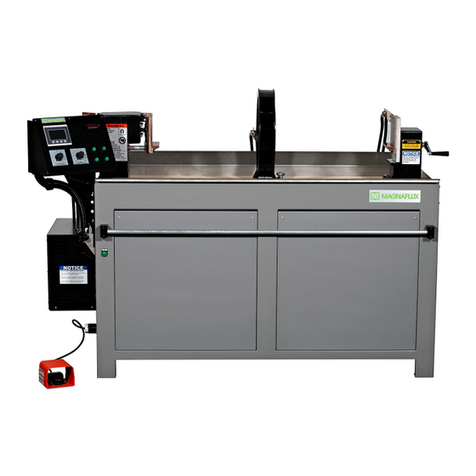
Magnaflux D-2000 Series User manual

D-2000 Series Revised March 2020
Page | 1-0
D-2000 SERIES

D-2000 Series Revised March 2020
Page | 1-1
TABLE OF CONTENTS
GENERAL SAFETY INSTRUCTIONS ............................................................................................. 1-2
SECTION 1 - EQUIPMENT SPECIFICATIONS ............................................................................... 1-3
Scope of this Manual ............................................................................................................ 1-3
Purpose of the Equipment .................................................................................................... 1-3
Equipment Characteristics .................................................................................................... 1-3
Equipment Specifications...................................................................................................... 1-4
Equipment Warranty………………………………………………………………………………..1-7
SECTION 2 - INSTALLATION and STORAGE ............................................................................... 2-1
General ................................................................................................................................. 2-1
Installation............................................................................................................................. 2-1
Preparation for Storage or Shipment .................................................................................... 2-8
SECTION 3 - OPERATING INSTRUCTIONS .................................................................................. 3-1
Operating Controls and Indicators ........................................................................................ 3-1
Daily Start Up and Operation Checklist ................................................................................ 3-7
Piece Part Setup ................................................................................................................... 3-9
Magnetizing Procedures ..................................................................................................... 3-10
Demagnetization ................................................................................................................. 3-11
Shutdown ............................................................................................................................ 3-12
Emergency Shutdown......................................................................................................... 3-12
SECTION 4 - MAINTENANCE ......................................................................................................... 4-1
General ................................................................................................................................. 4-1
Daily Operator Maintenance ................................................................................................. 4-1
Weekly Operator Maintenance ............................................................................................. 4-2
Monthly Operator Maintenance............................................................................................. 4-2
Periodic Internal Maintenance .............................................................................................. 4-2
Operational Checkout Procedures........................................................................................ 4-4
Initial Set-up .......................................................................................................................... 4-4
Circular (Contact) and Longitudinal (Coil) Magnetization Check .......................................... 4-5
SECTION 5 – TROUBLESHOOTING .............................................................................................. 5-1
Troubleshooting Stack (Firing Board) ................................................................................... 5-1
Troubleshooting Guide.......................................................................................................... 5-2
SECTION 6 – DRAWINGS & SPARE PARTS LIST........................................................................ 6-1
SECTION 7 – HOOD & BLACK LIGHT INSTALLATION................................................................ 7-1
Hood Installation ................................................................................................................... 7-1
Black Light Installation .......................................................................................................... 7-8
D-2000 Series Revised March 2020
Page | 1-2
GENERAL SAFETY INSTRUCTIONS
This manual provides information on how to install, operate, and maintain your Magnaflux magnetic particle
inspection machine.
Read these instructions carefully before operating or servicing your machine.
•Only trained personnel should operate or service this machine. Be familiar with your facility and local
procedures as well as Lock Out/Tag Out requirements before working with this machine.
•Read this entire manual before operating this machine.
•Wear safety glasses that conform to ANSI Standard Z87.1 while operating this machine.
•Do not wear loose clothing or jewelry while operating or servicing this machine.
•Inspect the machine daily for unsafe conditions; replace any worn or broken parts (see Section 4).
•Keep all unauthorized personnel away from the machine operating area.
•According to the American Conference of Governmental Industrial Hygienists (ACGIH)
recommendations, inspectors with pacemakers should avoid exposure to D.C. fields over 10 gauss; or
60 cycle A.C. field over 1.0 gauss. There are a variety of pacemakers with different susceptibilities to
magnetic fields. Wearers should discuss pacemaker limitations with their physicians and learn more
exactly what they should avoid, and whether they should be exposed to magnetic fields before
operating this equipment.
•When you are finished operating the machine, turn off all power.
•This machine was designed to help the end user comply with ASTM E-1444. Calibration frequency is
dictated by this standard.

D-2000 Series Revised March 2020
Page | 1-3
SECTION 1: EQUIPMENT SPECIFICATIONS
SCOPE OF THIS MANUAL
This manual provides essential information required for installation, operation, and maintenance of standard
Magnaflux D-2000 Series Stationary Magnetic Particle Inspection Machines.
PURPOSE OF THE EQUIPMENT
The equipment is used to inspect ferromagnetic parts by means of the magnetic particle inspection method.
Magnetic particle inspection (MPI) is a non-destructive method for revealing surface, and, under certain
conditions, sub-surface discontinuities. It consists of three basic operations:
1. Application of magnetic particles.
2. Establishment of a suitable magnetic field.
3. Inspection and evaluation of particle accumulations.
Discontinuities may exist in raw material from which parts are made, or, they may occur during processing or
fabrication of the parts, or, they may exist as cracks due to excessive service stresses. Discontinuities are
considered defects if their existence is detrimental to the usefulness of the part. Magnetic particle inspection
can readily and reliably locate discontinuities revealing manufacturing and/or service-induced defects.
EQUIPMENT CHARACTERISTICS
Stationary magnetic particle inspection units consist of a processing station and an integral power pack. The
power pack provides low-voltage, high-amperage 3-phase full wave direct current for magnetization and
reversing 3-phase full wave direct current for demagnetization.
The output current levels are governed by either 2 separate current control encoders or the HMI. Selection of
Contacts or Coil operation is provided by push buttons on the Operator Control Panel. A push button on the
Operator Control Panel, or a push bar, initiates the timed magnetizing current “shot.”
A digital ammeter provides a reading of the magnetizing current. The reading is held until the next current
“shot” is initiated. The wet bath is contained in a tank that runs the full length of the machine. A pump re-circu-
lates the particle in bath and provides flow to the spray nozzle or the Optional Autobath nozzles. Grilles cover
the tank, provide a work surface, and prevent parts from falling into the tank.
The air-operated headstock and adjustable locking tailstock provide the necessary clamping force to assure
good electrical contact with the part.
Parts clamped between the headstock and tailstock for circular magnetization may also be magnetized
longitudinally with the coil while clamped in the headstock and tailstock.
The bath is filled with magnetic particles. An ultraviolet black light causes the coated particles to glow,
revealing flaws in the part being tested.

D-2000 Series Revised March 2020
Page | 1-4
Pertinent data (e.g., the unit’s serial number, electrical specifications, and duty cycle rating) may be found on
the Magnaflux Data Plate, located on the headstock end of the unit.
EQUIPMENT SPECIFICATIONS
CONVENIENCE OUTLETS 2 each 115 volts AC, 10 amperes (for Black Light)
COMPRESSED AIR (1/8” NPT pipe connection) 90-120 psig
Input Specifications
The equipment can be fused based on less than the maximum amperage draw due to the duty cycle. Refer to
NEC Code Section 630.31 Ampacity of Supply Conductors and Table 630.31(A) (2) Duty Cycle Multiplication
Factors for Resistance Welders (NPFA National Electric Code 2011).
Table 1-1. Electrical Input
Model
Series
Input Volts
AC
Phase
Load
(Amperes)
Recommended Line
Fuse (Amperes)
Recommended Wire
Size (AWG)
D-2060
(SEE MOD AC
options below)
208
230
380
415
460
575
3
3
3
3
3
3
160
160
100
90
80
70
125
125
80
70
60
60
2
2
6
6
6
6
D-2100
(SEE MOD AC
options below)
208
230
380
415
460
575
3
3
3
3
3
3
400
400
245
220
200
160
300
300
200
175
150
125
0
0
2
2
4
4
MOD6 AC
(Optional for
D-2060 and
D-2100)
208
230
380
415
460
575
N/A
3
3
3
3
3
N/A
575
350
325
300
200
N/A
350
200
200
150
100
N/A
2/0
0
0
2
2
D-2100XL4
460
3
350
250
2/0
D-2100XL5
460
3
350
250
2/0
Output Specifications
*All contacts current ratings are based on the maximum current through a 2000 amp/100 mv shunt.
*Some coils may be capable of handling more current but these levels are based on the duty cycle of the unit.

D-2000 Series Revised March 2020
Page | 1-5
Table 1-2. Magnetization and Demagnetization Output
Model
Series Mode
Maximum Current (Amperes)* Current
Control Demag
Average (DC)
D-2060
Contacts
12” Coil
16” Coil
20” Coil
25” Coil
30” Coil
36” Coil
6000
4600
4400
4200
4000
3000
3000
Continuously
Variable
In all cases
Reversing
Decaying DC
D-2100
Contacts
12” Coil
16” Coil
20” Coil
25” Coil
10000
5800
5200
5000
4700
Continuously
Variable
In all cases
Reversing
Decaying DC
D-2100XL4
Contacts
25” Coil
Split Coil
10000
8000
6000
Continuously
Variable
In all cases
Reversing
Decaying DC
D-2100XL5
Contacts
25” Coil
Split Coil
10000
7800
6000
Continuously
Variable
In all cases
Reversing
Decaying DC
Table 1-3. Duty Cycle
Model Series Seconds “On” Seconds “Off”
D-2060 SERIES
At Maximum Output
At 1000 A. Output
0.5
0.5
10
5
D-2100 SERIES
At Maximum Output
At 1000 A. Output
0.5
0.5
20
5

D-2000 Series Revised March 2020
Page | 1-6
Dimensions and Capacities
Table 1-4. Part Weight Capacity
Description
Maximum Load
Pounds
Kilograms
Using contact pad mounted v-blocks to support part
300
136
Using contact pad mounted v-blocks to support part (with rotating heads)
70
32
Using rail mounted steady rests to support part
1500
680
Equipped with heavy duty frame option and rail mounted steady rests to support part
4000
1814
Table 1-5. Part Length Capacity
Table 1-6. Recommended Bath Level
Model No.
Length
Model No.
Gallons
Liters
D-2***
54" (137 cm)
D-2060 (2 door) 20 76
D-2***L
102" (259 cm)
D-2060L (3 door) 34 129
D-2***XL
146" (370 cm)
D-2060XL (4 door) 46 174
D-2100XL4 243” (617 cm)
D-2060XL2 (5 door) 58 220
D-2100XL5 278” (706 cm)
Table 1-7. Machine Weight
Model No.
Approximate Weight (Dry)
Approximate Weight (Crated)
Pounds
Kilograms
Pounds
Kilograms
D-2*** 1600 726 1875 850
D-2***L 1825 828 2100 952
D-2***XL 1925 873 2200 998
D-2100XL4 6600 3000
D-2100XL5 7500 3400

D-2000 Series Revised March 2020
Page | 1-7
Table 1-8. Overall Dimensions
Description D-2*** D-2***L D-2***XL D-2100XL4 D-2100XL5
Basic Unit (No Hood)
Length
Depth
Height
84½(215cm)
41(104cm)
60¼(153cm)
132½(336cm)
41(104cm)
60¼(153cm)
176½(448cm)
41(104cm)
60¼(153cm)
280½(712½cm)
41(104cm)
60¼(153cm)
317½(806½cm)
41(104cm)
60¼(153cm)
Basic Unit (Optional Hood)
Length
Depth (Hood Opened)
Depth (Hood Closed)
Height (Hood Opened)
Height (Hood Closed)
86(218cm)
50(127cm)
73(185cm)
120(305cm)
89½(227cm)
135(336cm)
50(127cm)
73(185cm)
120(305cm)
89½(227cm)
178(452cm)
50(127cm)
73(185cm)
120(305cm)
89½(227cm)
N/A N/A
EQUIPMENT WARRANTY
The Equipment Warranty Statement can be found on our Web site at the following link:
https://www.magnaflux.com/Files/Corporate/Equipment-Warranty-Statement.pdf

D-2000 Series Revised March 2020
Page | 1-8
PAGE LEFT BLANK
INTENTIONALLY

D-2000 Series Revised March 2020
Page | 2-1
SECTION 2: INSTALLATION AND STORAGE
GENERAL
This section contains information required for unpacking, inspecting, and setting up the magnetic particle
inspection unit. Information for preparing the inspection unit for shipment and storage is also included.
INSTALLATION
Location of Unit
Consider the following requirements before selecting a permanent location for the inspection unit:
1. A power source of the proper voltage, frequency and phase (as designated on the Magnaflux Data
Plate located on headstock end of inspection unit) capable of providing current per the nameplate.
2. A compressed air supply capable of providing minimum 90-120 psig at 5 cubic feet per minute.
3. A minimum of two feet is required at both ends and the rear of the inspection unit to ensure adequate
space for servicing and ventilation.
4. A firm, reasonably level floor capable of supporting the inspection unit and the materials awaiting
inspection.
5. Adequate space to accommodate a black light inspection hood (Optional), material storage, material
movement and access to the materials.
Unpacking
No special unpacking process is necessary. Observe normal precautions to prevent damage to inspection unit,
and adhere to standard practices for the removal of crating material, protective barrier materials and
preservatives.
Visually inspect the machine and Optional accessories for any apparent shipping damage, and to ascertain
that all accessories ordered have been received. If shipping damage is found, please contact the freight
company to report the damage before contacting Magnaflux Customer Service via phone at 847-657-5300, or
via e-mail at support@magnaflux.com.
Leveling
Check the tailstock rails for true level, shimming the legs as required. When the inspection unit is level, secure
it to the floor with a bolt through each leg.

D-2000 Series Revised March 2020
Page | 2-2
Electrical Connections
The inspection unit as supplied is internally wired for operation from a power source as designated on the
Magnaflux Data Plate (located on headstock end of inspection unit). When connecting the unit all local codes
should be followed. External wiring directions for operation on the designated voltage are as follows:
1. Open rear panel located on the headstock end, or Optional disconnect, to gain access to input power
terminal block.
WARNING: Turn off and lock-out the external disconnect switch (not normally supplied)
before opening the rear panel. Failure to disconnect incoming power could
result in severe electrical shock or death.
2. Connect external power source to the terminal block on the rear of the inspection unit, or the top
connectors in the Optional disconnect. Refer to Table 1-1 for recommended dual-element time delay
fuse size and power source conductor size.
WARNING: Magnetic particle baths can carry electrical current. Since operators will come
in contact with the bath during operation, proper grounding of the inspection
unit is essential. Failure to ground the inspection unit properly may result in an
electrical shock hazard. Check the ground connection with an ohmmeter. A
reading of 0 ohms denotes an acceptable ground connection.
In Figure 2-1 above, the rear headstock side panel has been removed. This is the location for the electrical
connection. Figure 2-2 above is a closer view of where the connection is located. The black wires on the right
side of the High Voltage label in Figure 2-2 would be the wires that the customer installs.
In Figure 2-3 above, the copper lug shown is the ground lug. The top punch out hole in the frame is for the
customer to run the wires through and connect to the terminal block located behind the High Voltage label.
Figure 2-2
Figure 2-1
Figure 2-3

D-2000 Series Revised March 2020
Page | 2-3
Table 2-1. Recommended Fuse Size
D-2060 and D-2060 MOD 2.5 AC
Input Volts AC Phase Full Load (Amps) Line Fuse (Amps) Wire Size (AWG) Ground wire
208
230
380
415
460
575
3
3
3
3
3
3
160
160
100
90
80
70
125
125
80
70
60
60
#2
#2
#6
#6
#6
#6
Same as line
or larger
D-2100 and D-2100 MOD 4.0
Input Volts AC Phase Full Load (Amps) Line Fuse (Amps) Wire Size (AWG) Ground Wire
208
230
380
415
460
575
3
3
3
3
3
3
400
400
245
220
200
160
300
300
200
175
150
125
#0
#0
#2
#2
#4
#4
Same as line
or larger
D-2060 MOD 6AC and D-2100 MOD 6AC
Input Volts AC Phase Full Load (Amps) Line Fuse (Amps) Wire Size (AWG) Ground wire
208
230
380
415
460
575
N/A
3
3
3
3
3
3
N/A
575
350
325
300
200
N/A
350
200
200
150
100
N/A
2/0
0
0
2
2
Same as line
or larger
Note: The equipment can be fused based on less than the maximum amperage draw due to the duty cycle.
Refer to NEC Code Section 630.31 Ampacity of Supply Conductors and Table 630.31(A) (2) Duty Cycle
Multiplication Factors for Resistance Welders (NPFA National Electric Code 2011). Some areas refer to 2
phase instead of 1 phase. The incoming power goes directly to an isolation transformer so the unit will operate
identically on 1 or 2 phase power.

D-2000 Series Revised March 2020
Page | 2-4
Air Supply
Connect a 90-120 psig compressed air supply to the air filter. Adjust the pressure regulating knob until the air
pressure gauge indicates 40 psi. Figure 2-4 and 2-5 below show this regulator on the headstock end of the
machine.
The air connection is required to operate the pneumatic headstock and pneumatic contactor, which is shown
below in Figure 2-6.
WARNING: If air is not connected to the machine, severe damage can occur.
Figure 2-6
Pump Connection
WARNING: Pump should not be run dry. Be sure to fill the tank with oil or water bath prior to
plugging in the pump.
After the tank is filled with oil or water bath, and the proper amount of magnetic particles, plug the pump in to
the outlet located on the operator’s end of machine. Figures 2-7 below shows the pump as it is shipped and
Figure 2-4
Figure 2-5

D-2000 Series Revised March 2020
Page | 2-5
normal operation. Figure 2-8 shows the front cover removed however you have to remove the entire cover to
do any maintenance.
NOTE: The following procedure should be performed by a qualified maintenance technician.
Ammeter Accuracy Verification
1. With the unit electrically installed, the compressed air supply connected, and the inspection hood
(optional) installed, connect the foot switch to the foot switch receptacle or the optional Dual Palm to
the Dual Palm receptacle on the left side of the unit. Refer to Figure 2-9 to locate both receptacles.
Figure 2-8
Figure 2-7
Foot Switch Receptacle
Dual Palm Receptacle
Figure 2-9

D-2000 Series Revised March 2020
Page | 2-6
2. Unlock and position tailstock where the digital test meter kit shunt can be supported by the tailstock
and headstock shelves. Lock tailstock.
3. Position the digital test meter kit shunt (Magnaflux Accessory Part Number 622350) as shown in
Figures 2-10 and 2-11, and specified in Table 4-5, between the headstock and tailstock.
Figure 2-10 Figure 2-11
4. Connect the shunt cable to the test meter shunt input as directed in the test kit instructions.
5. Check that the pressure gauge indicates 40 psi.
6. Turn on disconnect switch; Operator HMI and power indicator will light.
7. If equipped with the AUTOBATH option, toggle AUTOBATH and PUMP buttons to off. If equipped with
the AUTOMAG option, toggle AUTOMAG to off.
8. Press the foot switch or the Optional Dual Palm to firmly clamp the shunt in position between the
headstock and tailstock.
9. Press CONTACTS push-button to on.
10. Set the amperage using the CONTACT current control or use the AMPERAGE SETPOINT on the HMI
to a desired value.
11. Set digital test meter to FWDC.
12. Press MAG button. After the timed “shot,” both the unit’s digital ammeter and test kit ammeter should
display within ±10% or 50 Amps whichever is greater.
13. Repeat steps 10-12 at various setpoints as required.

D-2000 Series Revised March 2020
Page | 2-7
Coil Ammeter Accuracy Verification
1. This unit is designed with one meter. The signal to the meter comes from the same source as the
contacts. If the meter is accurate in the contact mode, the meter is considered calibrated for the all
modes.
Preparation of Bath
WARNING: Never operate the pump without bath in the tank. Operation of the pump without bath
may overheat the pump seal.
1. Be certain that the drain cock at the rear of the unit is closed.
2. Agitation system is checked for leaks prior to shipment with light oil. If using water bath, carefully
clean the entire system with liquid detergent solution and re-circulate, followed by a thorough water
rinse. If using oil bath, flush system with light oil (Specification MIL-L-15016) such as Magnaflux
Carrier II. (NOTE: All units are tested with the oil bath during the certification process by Magnaflux.
Look for the tag on the pump housing prior to adding the bath to the system.)
3. Prepare bath according to the manufacturer’s recommendations and any applicable specifications. For
proper particle agitation, DO NOT EXCEED VOLUME RECOMMENDED IN TABLE 1-6.
4. Press PUMP button on HMI. The button is dimly lit when off and brighter when on. Allow the bath to
agitate and circulate through the system.
Table 2-2. Recommended Bath Concentration
Magnaglo®
Magnaflux®
Water
Conditioners
14A
MG-410
20B
7C
WA-2B
WA-4
Recommended Concentration
Ounces/Gallon
Grams/Liter
1/6
1.25
1/10
0.75
1½
11.25
1¼
9.4
1
10.0
1 Part to
100 parts
water
Settling Volume (ml/100 ml
bath)
0.15-
0.25
0.05-0.15
0.15-0.25
1.1-1.7 N/A N/A
Use Centrifuge Tube Part #
8493
507923
8493
2461
N/A

D-2000 Series Revised March 2020
Page | 2-8
Checking Bath Concentration Using Settling Test
NOTE: The settling test applies to both oil and water suspensions. As water evaporates more quickly than oil,
water baths generally require more frequent maintenance. Check applicable specifications for test frequency.
1. Allow the pump to thoroughly agitate the suspension for at least fifteen minutes to assure uniform
particle distribution.
a. Run the suspension through a spray nozzle for at least one minute to assure the suspension in the
hose is fresh and agitated.
2. Using the spray nozzle, fill the centrifuge tube with agitated solution to 100 ml.
3. Centrifuge tube with solution should be demagnetized by one of the following methods:
a. Hold centrifuge tube with solution in the middle of the coil and initiate a demag cycle (1000A or
higher).
OR
b. Run the centrifuge tube with solution through a stand-alone demagnetization unit (S or SB-Series).
4. Place the centrifuge tube in its stand (Magnaflux Accessory Part Number 1837A) and allow the
suspension to settle for thirty minutes (water bath) or sixty minutes (oil bath) in a vibration-free location.
5. Observe the total level of settled particles. Graduations read directly in milliliters (ml). If a contaminant
layer is present, subtract from the total level to obtain magnetic particle concentration.
6. Illuminate the centrifuge tube and suspension with a black light (Optional). Fluorescence in the liquid or
presence of a non-fluorescent particle layer indicates a solution breakdown and requires replacement
of the tank solution.
7. If the solution concentration is outside the range of the manufacturer’s recommendations or applicable
specifications, adjust the amount of liquid or particles as required. Repeat steps 1 through 5 to verify
concentration.
8. Return the contents of the centrifuge tube to the tank and clean the centrifuge tube prior to the next
test.
PREPARATION FOR STORAGE OR SHIPMENT
Limited Storage
When the inspection unit will not be used for a period up to 30 days, it should be serviced as follows:
1. Open the Auto-bath valve (Optional).

D-2000 Series Revised March 2020
Page | 2-9
2. Open the drain cock at the rear of the inspection unit, drain all bath solution into a suitable container
and discard the used solution.
3. Remove and clean the grilles, agitator vee; then, replace these back on the unit, and close the drain
cock. The tank and spray nozzle can be cleaned using compressed air.
4. Open the valve (turn counterclockwise) at the bottom of the regulator/gauge/filter bowl and blow out.
Then, shut off the air supply to the machine.
5. Disconnect power from the inspection unit by placing the external disconnect switch in the off position.
6. Disconnect the foot switch or Dual Palm (Optional), and the black light (Optional). Pack and store in a
plastic bag or carton on the grilles.
7. Cover the tank with paper, cardboard or plastic to prevent the accumulation of dust, dirt or other
contaminants. Close the hood (Optional) curtains for added protection.
Long Term Storage and/or Shipment
1. Open the Auto-bath valve (Optional).
2. Open the drain cock at the rear of the inspection unit, drain all bath solution into a suitable container
and discard the used solution.
3. Remove and clean the grilles, agitator vee; then, replace these back on the unit, and close the drain
cock. The tank and spray nozzle can be cleaned using compressed air.
4. Open the valve (turn counterclockwise) at the bottom of the regulator/gauge/filter bowl, and blow out.
Then, shut off the air supply to the machine.
5. Lock the tailstock assembly close to the headstock.
6. Disconnect power from the inspection unit by placing the external disconnect switch in the off position.
Disconnect the three conductors from the terminal block. Disconnect the ground conductor from the
brass grounding screw.
7. Disconnect the foot switch or Dual Palm (Optional) and the black light (Optional). Pack and store in a
plastic bag or carton on the grilles.
8. Support the hood (Optional) at both ends and then remove the hardware securing the hood to the
inspection unit frame. Lower the hood and pack separately. Install the removed hardware back in the
frame.
9. Remove the mounting screws and shims securing the inspection unit to the floor.

D-2000 Series Revised March 2020
Page | 2-10
10. Use the original shipping materials if possible. If the original packaging is not available, fabricate a
shipping container with sufficient blocking, bracing, and bolting to protect the contents during shipment
and long-term storage. For overseas shipping, the shipping crate must be lined with sealed case liners.
For commercial level packing, fabricate a shipping container in accordance with Consolidated Freight
Classification Rules that will ensure safe transportation to the point of delivery. Estimated shipping
dimensions and weight are listed in Tables 1-7 and 1-8. Mark the crate(s) clearly to identify the
contents and denote which side is to be up.

D-2000 Series Revised March 2020
Page | 2-11
PAGE LEFT BLANK
INTENTIONALLY
Other manuals for D-2000 Series
1
This manual suits for next models
11
Table of contents
Other Magnaflux Industrial Equipment manuals

Magnaflux
Magnaflux A-2030 Series User manual

Magnaflux
Magnaflux A-2000 Series User manual

Magnaflux
Magnaflux D-2100 Series User manual

Magnaflux
Magnaflux M-2030 Series User manual

Magnaflux
Magnaflux Y6 Yoke User manual

Magnaflux
Magnaflux L-10 User manual

Magnaflux
Magnaflux M-2060 Series User manual

Magnaflux
Magnaflux ADH-2045 Series User manual

Magnaflux
Magnaflux Universal WE User manual

Magnaflux
Magnaflux Universal WE TOUCH with TCODE User manual