Magnetek IMPULSE G+ User manual

OVERVIEW
This procedure is a supplement to other documentation for the
IMPULSE•G+/VG+ Series 5 variable frequency drive (VFD). This
guide details the installation and setup of the VFD.
Before using the VFD-controlled equipment, the operator shall
read the operating manual of the hoisting machine, shall be
trained, and understand the hazards of operating of cranes, hoists,
or lifting devices.
When installing the VFD, follow the required wiring practices and
all applicable codes. Ensure that the mounting of components is
secure and that the environment, such as extreme dampness, poor
ventilation, etc., will not cause system degradation.
Read this document thoroughly before attempting installation.
Refer to the technical manual for circuit protection and wiring
recommendations, available at: www.cmco.com/magnetek
Step 1
Connect Motor and Line Power
The following figure shows the electrical connections for the input
power and motor terminals of the IMPULSE•G+/VG+ Series 5
VFD. Make the appropriate connections with power turned off.
Follow required wiring practices and applicable electrical codes.
Ensure the equipment is properly grounded, as shown.
DANGER! DANGEROUS VOLTAGES ARE PRESENT
WHEN VFD IS ON. Improper wiring can cause bodily
harm and damage to the equipment. Before applying
power to the IMPULSE•G+/VG+ Series 5, ensure the pro-
tective covers are fastened and wiring connections are
secure. After power has been turned OFF, wait at least 5
minutes until the charge indicator extinguishes com-
pletely before commissioning the VFD.
Step 2
Typical Connection Diagram
Below is a typical wiring diagram and connection points for the IMPULSE•G+/VG+ Series 5
VFD. Wiring connections should only be made by trained and authorized personnel when
power to the VFD is turned off.
Step 3
PG-X3 Encoder Feedback Card and Encoder Wiring
(IMPULSE•VG+ Series 5 Only)
This step explains the installation and encoder wiring of the PG-X3 encoder
feedback option card. WITH POWER OFF, install the PG-X3 card as shown
below. Make sure to follow required wiring practices and follow all
applicable codes.
Option Card Installation
This option card must be inserted into the CN5-C (left) connector.
Encoder Power Supply Encoder Connection
(Max. 200mA)
Select Encoder Power
Supply (IP, IG)
with Jumper CN3.
It is required to use a differential quadrature
encoder with A+, A-, B+, B- channels.
PG-X3 Encoder Wiring
A – Connector CN5-A
B – Connector CN5-B
C – Connector CN5-C
D – Insert PG-X3 into CN5-C
E – PG-X3 option card
F – Mounting screws
G – LED status ring board
H – Front cover
I – Digital operator keypad
A – Terminal block (TB1)
B – Installation holes
C – Jumper for PG power supply voltage (CN3)
D – Terminal block (TB2)
E – Connector (CN5)
PG-X3 Option Card
Default
IMPORTANT: Verify Encoder
Power Supply Rating
V
B+ Z+ Z- SD FEA- B-A+
PG-X3 Terminals
a+ a- b- z+IG SGIP b+ z+
TB1
TB2
+ -
Encoder
Power
Encoder Signals
PG
(Required for Closed Loop Vector Operation)
IMPULSE®•G+/VG+ Series 5 Variable Frequency Drive
Quick Start Guide
N49 W13650 Campbell Drive
Menomonee Falls, WI 53051
Phone: 262.783.3500
Fax: 262.783.3510
Toll-Free Phone: 800.288.8178
Toll-Free Fax: 800.298.3503
For questions regarding service or technical information contact:
1.833.SVC.CMCO (1.833.782.2626)
International Service
Outside the U.S. & Canada call 1.262.783.3500, press 3
www.cmco.com/magnetek
IMPULSE•G+/VG+ Series 5 Quick Start Guide
144-80081 R0
August 2023 © Copyright 2023 Magnetek

Step 4
Keypad Navigation and Menu Displays
This step shows the keypad menu structure and how to access the
Parameter and Monitor locations along with the locations for Parameter
Backup, Auto-Tuning, Diagnostic Tools, and Time Settings.
Make sure all protective covers have been re-attached and power is turned
on. DO NOT RUN THE MOTOR.
NOTE: Refer to the technical manual for detailed information on the
parameters and monitors.
Step 5
Select a Control Method
This step explains the available Control Method settings.
V/f:
Set parameter A01-02 = 0 (V/f).
Only available for IMPULSE•G+ Series 5 and is recommended for most Traverse
and Mechanical Load Brake hoist applications.
Open Loop Vector:
Set parameter A01-02 = 1 (Open Loop Vector).
Only available for IMPULSE•G+ Series 5 and is recommended for Traverse and
Mechanical Load Brake hoist applications that require finer speed control or
torque limiting.
Closed Loop Vector:
Set parameter A01-02 = 3 (Closed Loop Vector).
Only available for IMPULSE•VG+ Series 5 and is locked to this setting. It is
recommended for Hoist applications without load brake and requires encoder
feedback.
NOTE: An Auto-Tune is recommended when using the Open Loop Vector or Closed
Loop Vector control methods.
Step 6
Select a Motion
This step explains how to configure the VFD for a Hoist or Traverse application.
Traverse:
Set parameter A01-03 = 0 (Traverse).
Hoist (with Mechanical Load Brake):
Set parameter A01-03 = 1 (Standard Hoist).
Not available for IMPULSE•VG+ Series 5.
Hoist (with No Load Brake):
Set parameter A01-03 = 2 (NLB Hoist).
Not available for IMPULSE•G+ Series 5.
NOTE: An Auto-Tune is recommended when using a No Load Brake Hoist motion.
Step 7
Select a Speed Reference
This step lists the Speed Reference settings.
NOTE: Default speed settings will be automatically applied via X-Press
Programming. See technical manual for more details and wiring instructions.
2-Speed Multi-Step: A01-04 = 0 3-Step Infinitely Variable: A01-04 = 4
3-Speed Multi-Step: A01-04 = 1 Uni-Polar Analog: A01-04 = 5
5-Speed Multi-Step: A01-04 = 2 Bi-Polar Analog: A01-04 = 6
2-Step Infinitely Variable: A01-04 = 3
Step 8
Auto-Tuning with Motor
In this step, the IMPULSE•G+/VG+ Series 5 VFD is set up for use with the motor.
Make sure all protective covers have been re-attached and then apply full line
power to the VFD. DO NOT RUN THE MOTOR.
V/f:
Select “Stationary Line-Line Resistance”
Open Loop Vector and Closed Loop Vector:
Decouple motor from load and disengage brake.
Select “Rotational Auto-Tuning”
When prompted, enter the following motor parameters:
Motor Rated Power (US: HP, Europe: kW)
Motor Rated Voltage (e.g., 230 V, 460 V)
Motor Rated Current (e.g., 22.0 A)
Motor Base Frequency (e.g., 60.0 Hz)
Number of Motor Poles (e.g., 4 Poles)
Motor Base Speed (e.g., 1750 rpm)
Encoder Pulse Count (e.g., 1024 PPR)
Motor No-Load Current (e.g., 5.0 A)
Motor Rated Slip Frequency (e.g., 2.90 Hz)
Motor No-Load Voltage (e.g., 391.0 VAC)
IMPULSE®•G+/VG+ Series 5 Variable Frequency Drive
Quick Start Guide
www.cmco.com/magnetek
IMPULSE•G+/VG+ Series 5 Quick Start Guide
144-80081 R0
August 2023 © Copyright 2023 Magnetek
N49 W13650 Campbell Drive
Menomonee Falls, WI 53051
Phone: 262.783.3500
Fax: 262.783.3510
Toll-Free Phone: 800.288.8178
Toll-Free Fax: 800.298.3503
For questions regarding service or technical information contact:
1.833.SVC.CMCO (1.833.782.2626)
International Service
Outside the U.S. & Canada call 1.262.783.3500, press 3

WARNING! SUDDEN MOVEMENT HAZARD. The motor will spin
during a Rotational Auto-Tune.
WARNING! ELECTRIC SHOCK HAZARD. High voltage will be
supplied to the motor when Auto-Tuning is performed. Do not
touch the motor during Auto-Tuning.
Encoder Direction
Check the motor speed monitor U01-05
while turning the motor manually in forward
direction (CW). If the sign displayed is
negative, power down the VFD, wait at
least five minutes until the charge
indicator extinguishes completely, then
swap encoder wires A+ with A- on the
PG-X3 card. Next, power up the VFD and
repeat this test. Or, reverse the encoder
direction with parameter F01-02.
Frequently Asked Questions
Question: How do I reset the VFD parameters back to
factory default settings?
Answer: There are two options. Setting A01-05 = 1110
will revert the parameters to the settings saved at the
factory. Setting A01-05 = 2220 will revert all parameters
back to default.
Question: How do I adjust the time it takes the motion to
speed up or slow down?
Answer: Adjust the acceleration time parameter b05-01
and deceleration time parameter b05-02.
Question: How do I prevent the occurrence of an OV
fault (overvoltage) while my motor is ramping down?
Answer:
Increase deceleration time parameter b05-02
and check braking resistor.
Question: How do I prevent the occurrence of an OL1
fault (overload) while my motor is ramping down?
Answer: Verify motor rated current parameter E02-01
and motor overload protection time parameter L01-02.
Question: How can I run my motor above the base
motor speed?
Answer: Increase the value of parameter E01-04
Maximum Frequency. For hoists, the Ultra-Lift feature is
recommended. Verify that the motor and system allow
for this.
Question: How can I change motor direction without
changing the motor leads?
Answer: Set parameter b03-04 = 1 (exchange phases).
Question: What should I do when the VFD detects a
brake failure and displays a BE6 or BE8 fault?
Answer: Do not turn off power! Lower the load to the
ground and inspect the brakes.
Question: On no load brake (NLB) hoist applications,
why does the brake stay open temporarily at the end of a
run?
Answer: This feature is called Load Float and reduces
wear on the brakes. See parameter C08-10 to adjust the
time.
Question: Where can I find troubleshooting information
regarding faults and alarms?
Answer: Reference the technical manual.
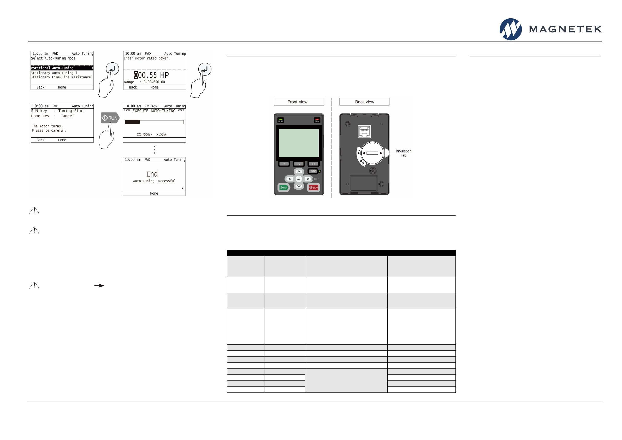
Step 9
Remove Keypad Insulation Tab
Detach the keypad and pull the insulation tab located on the back, next to the battery compartment.
The battery will now maintain the date and time settings.
Refer to Step 4 for the location of the Set Date/Time menu.
Step 10
Quick Start Parameters
The following table lists commonly used parameters as well as frequently asked questions.
Refer to Step 4 for the location of the parameters.
Parameter Description Settings Comments
A01-01 Access Level 0 = Operation
1 = User
2 = Advanced (Default)
3 = Expert
Advanced level contains the most
commonly used parameters and
hides the rest. Expert level contains
every available parameter.
A01-02 Control Method 0 = V/f
2 = Open Loop Vector*
3 = Closed Loop Vector*
* Auto-Tune Recommended
A01-03 Motion 0 = Traverse
1 = Hoist w/ Load Brake (G+ only)
2 = Hoist w/o Load Brake (VG+ only)
A01-04 Speed Reference 0 = Two-Speed Multi-Step
1 = Three-Speed Multi-Step
2 = Five-Speed Multi-Step
3 = Two-Step Infinitely Variable
4 = Three-Step Infinitely Variable
5 = Uni-Polar Analog (0-10VDC, 4-20mA)
6 = Bi-Polar Analog (-10 – +10VDC)
b01-01 – b01-16 Speed References 0.00 - 300.00 Hz Limited by E01-04
b05-01 Acceleration Time 0.0 - 60.0 Seconds
b05-02 Deceleration Time 0.0 - 60.0 Seconds
E02-01 Motor Rated FLA Dependent on o02-04 Setting See Motor Nameplate
H01-xx Digital Inputs
See Technical Manual for Settings
Terminals S1 - S8
H02-xx Digital Outputs Terminals M1-M2, M3-M4, M5-M6
H03-xx Analog Inputs Terminals A1, A2, A3
H04-xx Analog Outputs Terminals AM, FM
IMPULSE®•G+/VG+ Series 5 Variable Frequency Drive
Quick Start Guide
www.cmco.com/magnetek
IMPULSE•G+/VG+ Series 5 Quick Start Guide
144-80081 R0
August 2023 © Copyright 2023 Magnetek
N49 W13650 Campbell Drive
Menomonee Falls, WI 53051
Phone: 262.783.3500
Fax: 262.783.3510
Toll-Free Phone: 800.288.8178
Toll-Free Fax: 800.298.3503
For questions regarding service or technical information contact:
1.833.SVC.CMCO (1.833.782.2626)
International Service
Outside the U.S. & Canada call 1.262.783.3500, press 3
Other manuals for IMPULSE G+
1
This manual suits for next models
2
Other Magnetek Industrial Equipment manuals