5/5
1.2 Display and Setup
1.2.1 User interface buttons
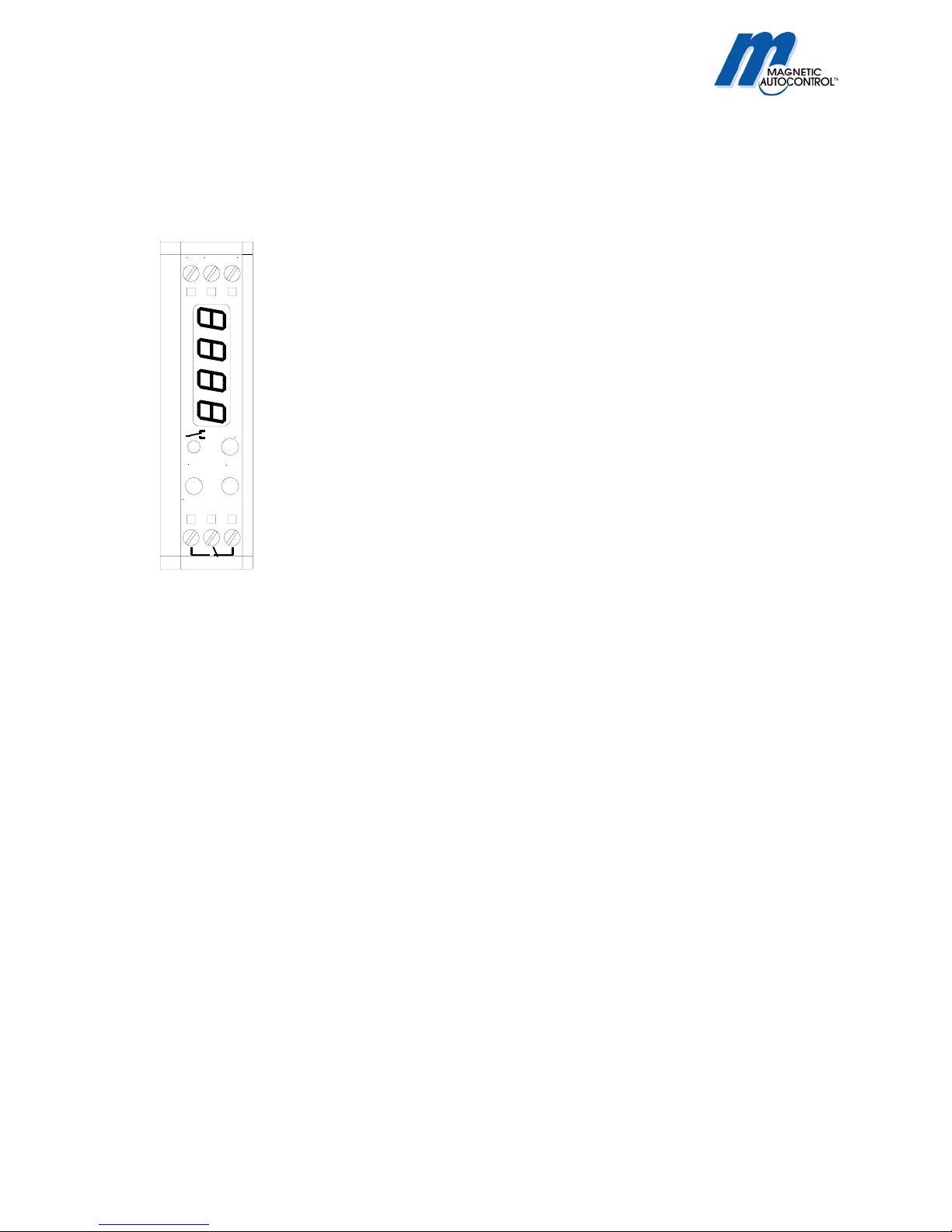
The VEK CN1 digital counter is adjusted with the three (3) user interface buttons located on top of the unit. The
display shows the current menu and status of the setup. The buttons have following functionality:
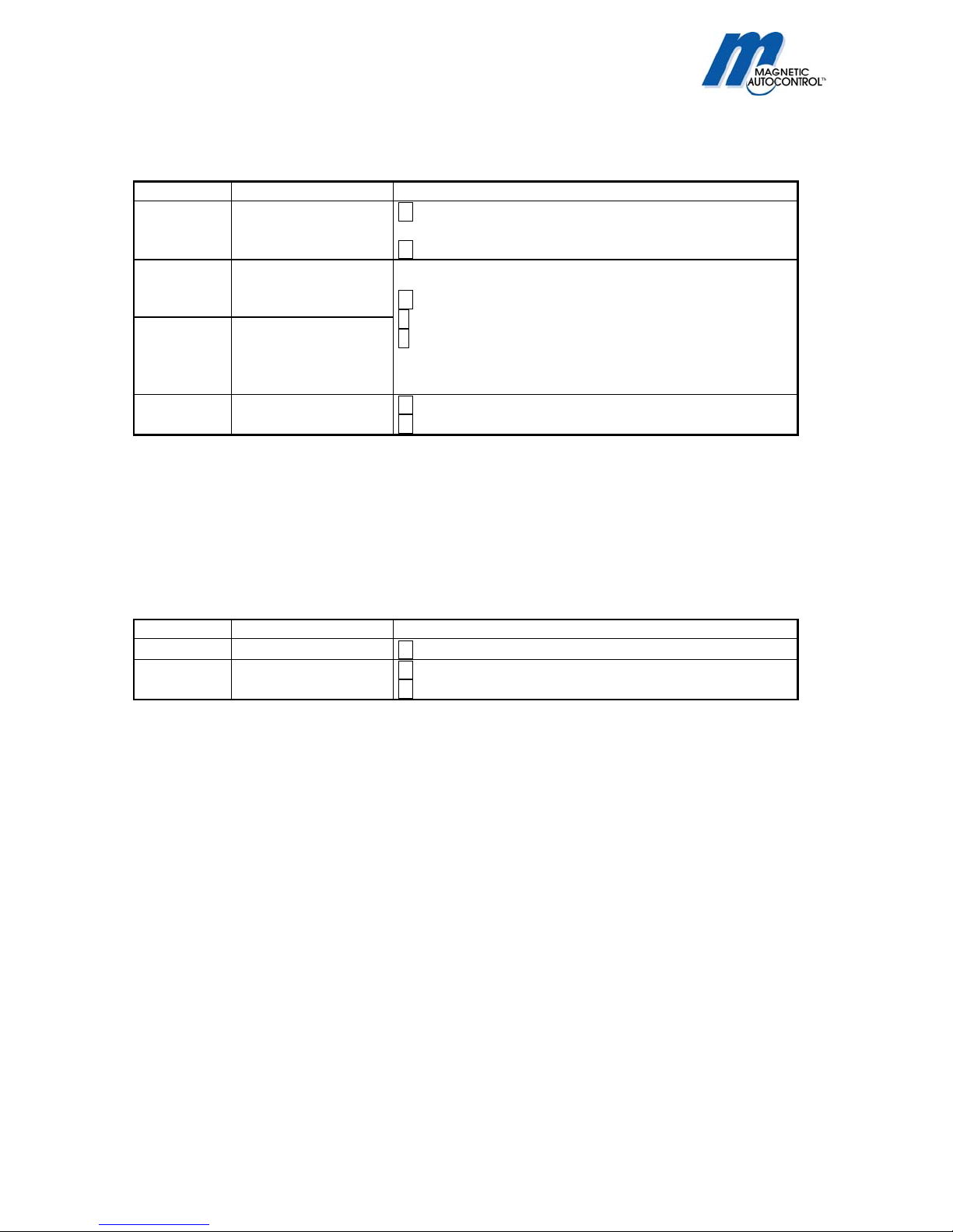
Button Function
M Short Next Menu, next digit, Cancel settings.
(Mode) Long Activate System menu, Save changes, exit menu.
∧Short Display value increments + 1
(UP) Long Display value fast increments
∨Short Display value increments – 1
(DOWN) Long Display value fast decrements
Two simultaneously Cancel changes, back to operating mode.
The menu is divided in base menu and system menu. During setup the flashing display signalizes that the
settings aren’t saved yet. If the unit was idle for 30sec. the unit goes back to normal operating mode without
saving the changes.
1.2.2 Power Failure
During loss of power the current count values and setup are saved. When the power returns the unit goes back
in normal operating mode but signalizes with the flashing display that there was a loss of power and the open
space count must be checked and if necessary updated.
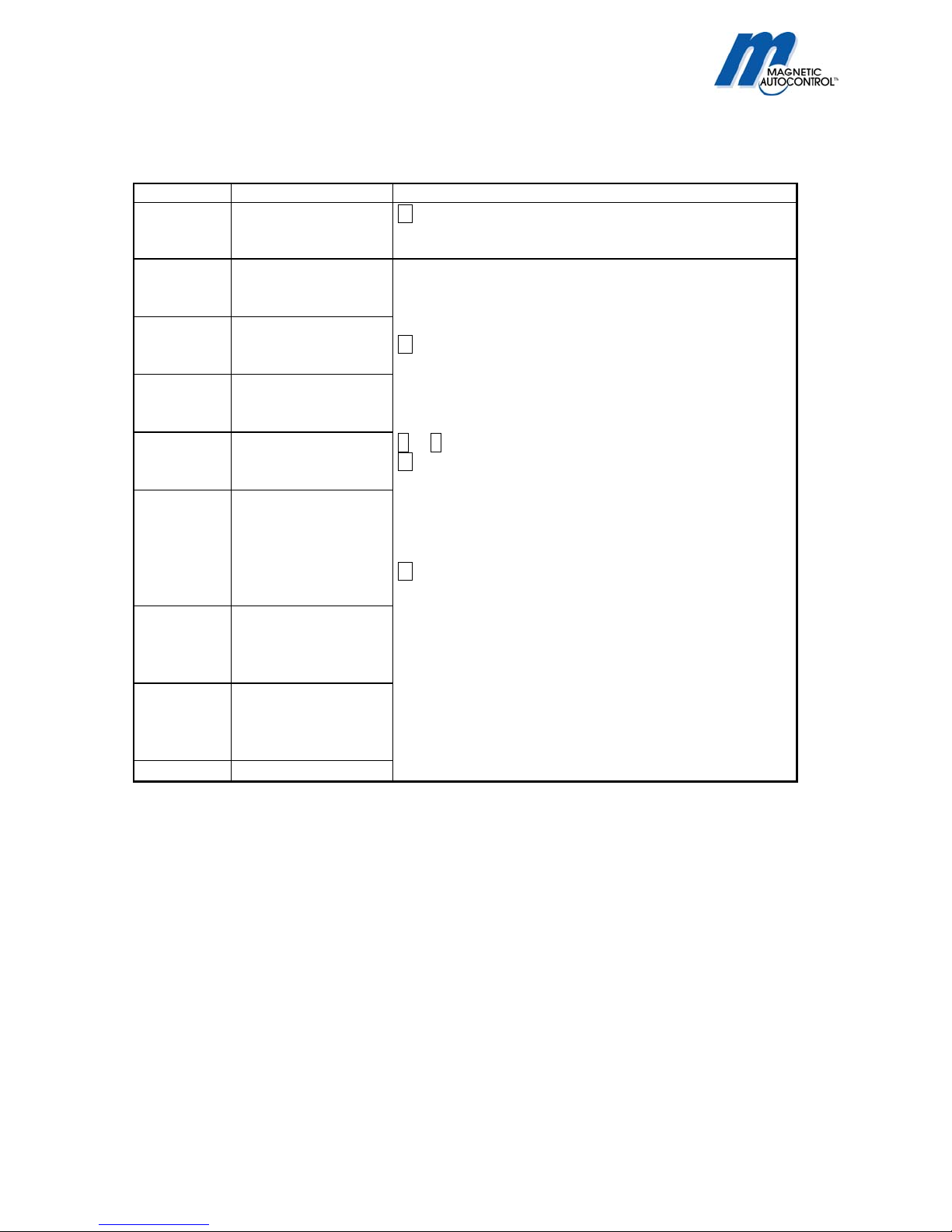
Display Status Setting
1234
Flashing
Return after loss of
power ∧or ∨→Update open space count
M →Confirm existing count is correct.
1.2.3 Display during normal operation
In normal operating mode you can have the display show either how many vehicles entered the car-park or how
many open spaces are left (see 1.4.1Operating Mode/Switching point). The relay status is displayed with the
LED-Light. The input status are displayed with 4 dots. Special statuses are directly displayed.
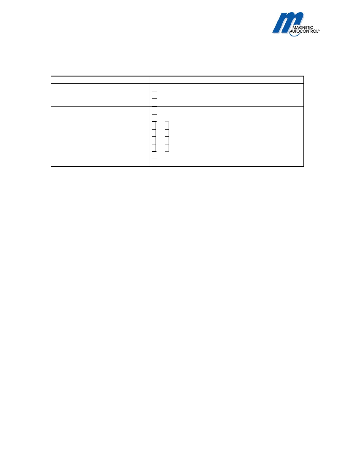
Display Status
Number, for example 1234 Normal operation, Current count
Number /occu alternating
display
Current count, Output manually set to “occupied”
Number /FrEE alternating
display
Current count, Output manually set to “free”.
0000 Reset Input active (Optional)
Dots Input Status, left to right 1,2,3,4
LED on/off Output relay status: activated = on/deactivated = off
Display off if unit was idle for
30sec.
Power save mode
Note:
1. If one of the four (4) input counter display is activated the display will not switch back to normal operating
display by itself.
2. If the Power save mode is activated the display will turn off when the unit was idle for more than 30 sec. By
pressing the M-Button the display can be turned on again (see 1.4.6 Power Save Mode)