The Magstim Company Ltd.© 9
Product Guarantee
The Magstim Company Ltd. guarantees the effectiveness of both materials and
workmanship for a period of two years from the date of shipment for the following
products:
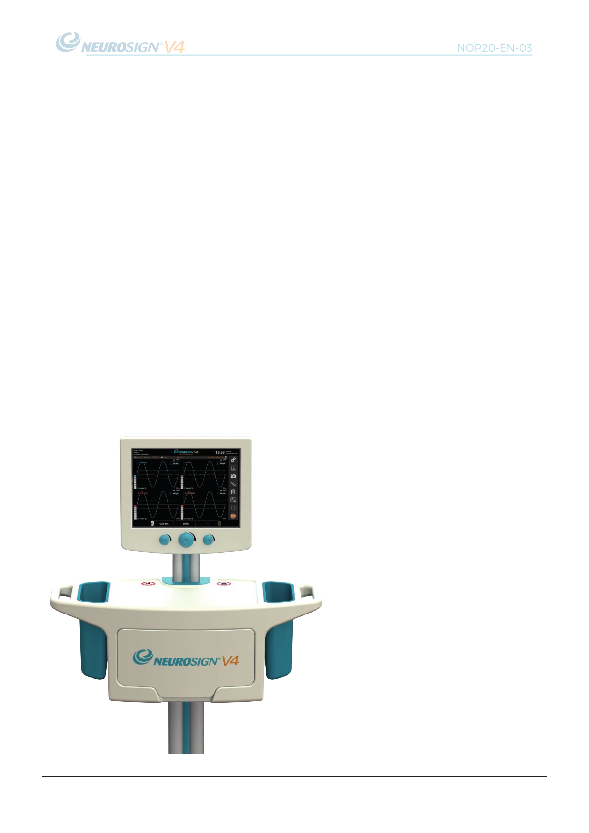
Neurosign®V4 Intraoperative Nerve Monitor - P/N: 4230-00
Neurosign®V4 Stimulator Pod - P/N: 4440-00
Neurosign®V4 Pre-amplifier - 4-Channel - P/N: 4444-00
Neurosign®V4 Pre-amplifier - 8-Channel - P/N: 4448-00
Neurosign®V4 Mute Sensor - P/N: 4225-00
The Magstim Company Ltd. reserves the right to perform guarantee services in its
factory, at an authorised repair station, or at the customer’s installation at the
discretion of the company.
The Magstim Company Ltd. guarantees to repair or replace defective equipment or
parts, free of charge within the guarantee period, provided that the said defects occur
during normal use. Replacement will be only at the company's discretion where a
repair is not possible and/or not feasible.
Disposables such as batteries, electrodes and stimulating probes are not covered
under this guarantee.
Claims for damages during shipment must be filed promptly with the transportation
company. All correspondence concerning the equipment must specify the model
name and/or number, as well as the serial number, exactly as they appear on the
equipment invoice/unit.
Improper use, mishandling, tampering with, or operation of the equipment without
following operating instructions will void this guarantee and release The Magstim
Company Ltd. from any further obligations under this guarantee.
The Magstim Company Ltd. will accept responsibility for effects on safety, reliability
and performance of the equipment provided:
• Any modifications, repairs or servicing of the products are carried out by The
Magstim Company Limited or persons authorised by the company;
• The electrical installation of the relevant room complies with local regulations
and;
• The equipment is used in accordance with the user manual.
The Magstim Company Ltd. guarantees to support the products stated above for a
period of seven years from date of shipment and where the terms of this guarantee
have been met. Servicing and replacement parts will be available within this time.
The Magstim Company Ltd. cannot guarantee that spare parts will be available
after this time. Please see "4.4 Servicing & Device Lifetime" on page 31 for more
information.