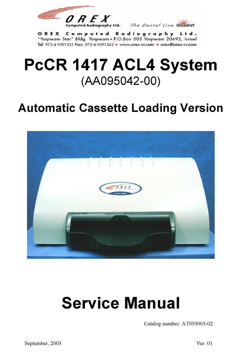
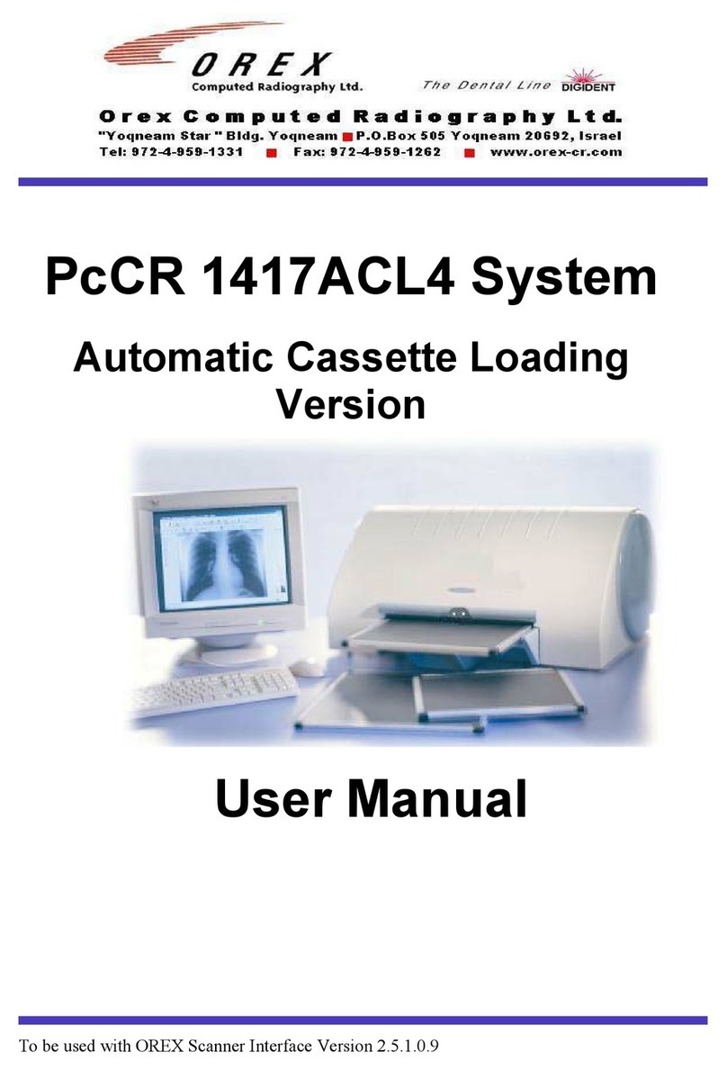
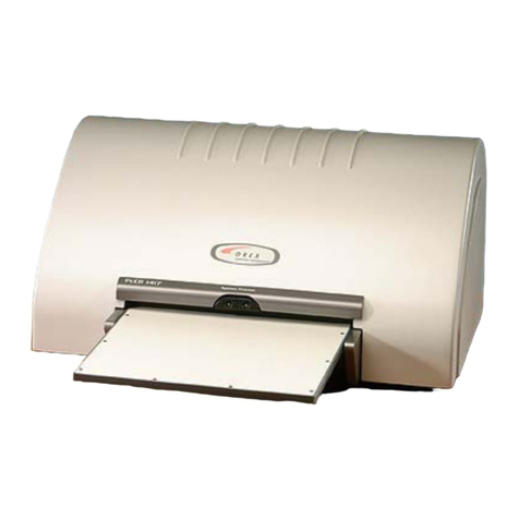
OREX PcCR 1417 User manual

January, 2003 Ver. 01
PcCR 1417 ACL4 System
Automatic Cassette Loading
Version
Service Manual
Catalog number: AT095045-00

OREX Ltd. is a market innovator in the field of portable Computed Radiography Technologies—
designed and priced for low-volume clinic or field unit needs.
Founded in 1995 under the name of Digident, the company initially entered the market of desktop
dental radiography providing high quality, portable CR reading units for dental and orthodontic
professionals around the world. The secret of Digident/OREX’s rapid success lies in the best cost-
performance ratio on the market.
OREX designs, manufactures and markets phosphor image laser scanners. These units replace the
traditional x-ray film and light box. The scanners allow the user to immediately read the x-ray image
from the phosphor plate, and transfer it to a DICOM 3 compatible digital computer file. Once
transferred, users can manipulate the digital image for close-up screening, or transmit it for long-
distance consultation. After each scan, the phosphor plates are automatically erased by the unit, ready
for re-use.
OREX provides clients with a full solution including phosphor image plates, laser readers, software
for image processing, storage, retrieval and communication in Picture Archiving and
Communications System (PACS) compatible format.
The company’s mission is to become a leading provider of compact personal CR systems. Following
the successful penetration of the global dental market, the company changed its name from Digident
to OREX and expanded its markets and product lines to serve the dental, medical, military, industrial
and veterinary fields.
“We are committed to assisting our customers in obtaining maximum value from
OREX products by providing excellent support at exceptional value.”
Technical Support
Israel Headquarters: Tel: ++972-4-959-1331
Fax: ++972-4-959-1262
US Office: Tel: ++1-617-244-9000
Toll free: 1-888-844-7775 (within US only)
Fax: ++1-617-244-9020
Document Part Number: AT095045-00
Printed in Yokneam, Israel 2002
Copyright © 2002, all rights reserved

Safety
Laser Safety Instructions
1. During nominal operation, the scanner is closed
and sealed with a protective cover. That is for
preventing the laser from being exposed to the
outside area, and to prevent access to the laser
by the user.
2. During nominal operation, the cover should not be
removed. Removing the cover shall be done only
for service purposes, and by a qualified technician
for service operations.
3. Any service operation shall be done without
activating the laser unit. Disconnecting the
relevant connector on the laser board will
disconnect the power supply to the laser, and
deactivate the laser unit for service operations.
4. In case the laser must be operated during service
operation, the service technician shall make sure
that the optical unit is located within the cylinder
area, where the laser beam is blocked and cannot
leak outside.
5. When a service operation is taking place, with
cover removed and laser activated, avoid direct
exposure to the laser beam.


Table of Contents i
Table of Contents
1. Terms and Conventions..............................................................1-1
2. Maintenance and Service ...........................................................2-1
2.1 General ............................................................................................... 2-1
2.2 Service Report .................................................................................... 2-1
2.3 Preventive Maintenance ..................................................................... 2-1
2.3.1 Cleaning the Rollers ............................................................... 2-1
2.4 Service Operations ............................................................................. 2-2
2.4.1 General ................................................................................... 2-2
2.4.2 Removing the Cover............................................................... 2-3
2.4.3 Removing the bottom service panel ....................................... 2-6
2.4.4 Replacing USB board............................................................. 2-7
2.4.5 Replacing the Motion board................................................... 2-9
2.4.6 Replacing the Sensor board.................................................. 2-11
2.4.7 Replacing a locating sensor.................................................. 2-12
2.4.8 Replacing erase Lamps board .............................................. 2-13
2.4.9 Replacing Laser.................................................................... 2-14
2.4.10 Replacing Laser board........................................................ 2-15
2.4.11 Replacing PM board & PM assembly ................................ 2-16
2.4.12 Replacing Rollers motor..................................................... 2-18
2.4.13 Replacing Loader Assembly .............................................. 2-20
2.4.14 Replacing Slide Stepper motor........................................... 2-22
2.4.15 Replacing Rotational motor ............................................... 2-24
2.4.16 Replacing 15V power supply ............................................. 2-28
2.4.17 Replacing 5V/12V power supply ....................................... 2-29
2.4.18 Replacing 12V power supply ............................................. 2-30
2.4.19 Replacing Erase Lamps...................................................... 2-32
2.4.20 Replacing Inverters ............................................................ 2-34
2.4.21 Replacing the Slide............................................................. 2-36
3. Component Description..............................................................3-1
3.1 General ............................................................................................... 3-1
3.2 USB .................................................................................................... 3-3
3.2.1 Location.................................................................................. 3-3
3.2.2 Component ............................................................................. 3-3
3.2.3 Description ............................................................................. 3-4
3.3 Motion board ...................................................................................... 3-1

ii Table of Contents
3.3.1 Location.................................................................................. 3-1
3.3.2 Component ............................................................................. 3-1
3.3.3 Description ............................................................................. 3-2
3.4 Sensor Board ...................................................................................... 3-4
3.4.1 Location.................................................................................. 3-4
3.4.2 Component ............................................................................. 3-4
3.4.3 Description ............................................................................. 3-5
3.5 Erase lamps board .............................................................................. 3-7
3.5.1 Location.................................................................................. 3-7
3.5.2 Component ............................................................................. 3-7
3.5.3 Description ............................................................................. 3-8
3.6 Laser ................................................................................................... 3-9
3.6.1 Location.................................................................................. 3-9
3.6.2 Component ............................................................................. 3-9
3.6.3 Description ........................................................................... 3-10
3.7 Laser board....................................................................................... 3-11
3.7.1 Description ........................................................................... 3-11
3.7.2 Description ........................................................................... 3-11
3.7.3 Description ........................................................................... 3-12
3.8 PM Assembly ................................................................................... 3-13
3.8.1 Location................................................................................ 3-13
3.8.2 Component ........................................................................... 3-13
3.8.3 Description ........................................................................... 3-14
3.9 Rollers motor.................................................................................... 3-15
3.9.1 Location................................................................................ 3-15
3.9.2 Description ........................................................................... 3-15
3.10 Stepper Motor – Carriage................................................................. 3-16
3.10.1 Location.............................................................................. 3-16
3.10.2 Component ......................................................................... 3-16
3.10.3 Description ......................................................................... 3-17
3.11 Stepper Motor – Slide ...................................................................... 3-18
3.11.1 Location.............................................................................. 3-18
3.11.2 Component ......................................................................... 3-18
3.11.3 Description ......................................................................... 3-19
3.12 Rotation motor.................................................................................. 3-20
3.12.1 Location.............................................................................. 3-20
3.12.2 Component ......................................................................... 3-20
3.12.3 Description ......................................................................... 3-21
3.13 15v power supply ............................................................................. 3-22

Table of Contents iii
3.13.1 Location.............................................................................. 3-22
3.13.2 Component ......................................................................... 3-22
3.13.3 Description ......................................................................... 3-23
3.14 12V/5V power supply ...................................................................... 3-24
3.14.1 Location.............................................................................. 3-24
3.14.2 Component & Description ................................................. 3-24
3.15 12V power supply ............................................................................ 3-25
3.15.1 Location.............................................................................. 3-25
3.15.2 Component & Description ................................................. 3-25
3.16 Erase Lamps ..................................................................................... 3-26
3.16.1 Location.............................................................................. 3-26
3.16.2 Component ......................................................................... 3-26
3.16.3 Description ......................................................................... 3-27
3.17 Inverters............................................................................................ 3-28
3.17.1 Location.............................................................................. 3-28
3.17.2 Component & Description ................................................. 3-28
4. Appendix A: Required Tools for FSE.......................................4-1
5. Appendix B: Service Report ......................................................5-1
6. Appendix C: Cleaning the Rollers.............................................6-1

iv List of Figures
List of Figures
Figure 1: Component Description – Block Diagram ..............................................................3-2
Figure 2: Attaching The Cleaning Tray ..................................................................................6-1
Figure 3: The Cleaning Strips .................................................................................................6-2

Terms and Conventions 1-1
1. Terms and Conventions
The following abbreviations are used throughout this manual:
Term Meaning
FSE Field Service Engineer
PSP Photo-Stimulable Phosphor
USB Universal Serial Bus


Maintenance and Service 2-1
2. Maintenance and Service
2.1 General
This chapter describes routine maintenance and service operations (in case
of failures) performed on the PcCR 1417 by FSEs authorized by Orex.
For the required tools, please refer to Appendix A.
2.2 Service Report
With the completion of any servicing procedure, photocopy the Service
Report in Appendix B, fill it out, and send it to the Orex service department
at the following:
Israel:
Fax: (+972) -4- 9591262
Email: support@orex-cr.com
USA:
Fax: (+1) -617-244-8888
2.3 Preventive Maintenance
2.3.1 Cleaning the Rollers
The PcCR 1417 has two rollers that pull the plate from the cassette
into the scanner and push it back out into the cassette. Over time,
the rollers accumulate dirt or dust.
The rollers should be cleaned periodically to remove dust and
small particles. The roller-cleaning device enables you to clean the
rollers that feed the image plate from the cassette into the reader.
The Cleaning device includes the following items:
1. Cleaning tray
2. Cleaning plate with adhesive strips covered with protective
paper/a protective envelope.
Refer to Appendix C for detailed information.

2-2 Maintenance and Service
2.4 Service Operations
2.4.1 General
Only FSEs authorized by Orex are allowed to conduct any service
operation described in this chapter. If a person who is not an FSE
authorized by Orex conducts any operation described in this
chapter, it will cause the warranty for the PcCR 1417 to be
considered null and void.
After any service operation, a report must be filled out and sent to
the Orex service department. The Service Report is located in
Appendix D.

Maintenance and Service 2-3
2.4.2 Removing the Cover
For any service operation, the cover of the scanner must be
removed. After the service operation is finished, the cover must be
secured back to the scanner. Before removing the main cover, it is
necessary to remove the back service panel.
2.4.2.1 Service Panel
1 Locate the service panel at the rear of the system
2 Remove the 2.5 mm Allen screws that attach the back service
door to the cover; then remove the service door

2-4 Maintenance and Service
2.4.2.2 Main Cover
1 The cover is secured to the system with eleven Philips screws
around the base of the system
2 When opening the cover, do not place the scanner on its back
(bottom-side up). Pull the system to the edge of the table and
open the screws on the bottom. Repeat this for all sides of the
system, and when all the screws are open, lift the cover up and
remove it from the system.

Maintenance and Service 2-5
Position scanner as shown to remove the screws from the bottom.
This method will prevent damage to the cover.

2-6 Maintenance and Service
2.4.3 Removing the bottom service
panel
1. Place the system on its back (bottom-side up).
2 Remove the screw attaching the bottom panel to the system
(marked with “A”)
3 Slide the bottom panel upwards and remove it from the system.
A

Maintenance and Service 2-7
2.4.4 Replacing USB board
1. Open the back panel
2. Remove the 2.5mm Allen screws that secure the USB bracket.
3. Gently pull out the USB board.
4. Disconnect the cables leading to the back of the USB board.

2-8 Maintenance and Service
5. Place the new USB board. Re-connect the following connectors:
1) Flex cable 2) Power cable 3) Flat cable
6. Push the USB board back to its place and secure with the Allen
screws.

Maintenance and Service 2-9
2.4.5 Replacing the Motion board
1. Open the back panel.
2. Remove the 2.5mm Allen screws at the left side of the Motion
Board bracket.
3. Gently pull out the Motion Board.
4. Disconnect the cables from the Motion Board.

2-10 Maintenance and Service
5. Pull out the Motion Board and replace it with the new one.
6. Connect the cables and secure the bracket with the Allen screw.
Other manuals for PcCR 1417
2
Table of contents
Other OREX Medical Equipment manuals
Popular Medical Equipment manuals by other brands

Storz
Storz XENON NOVA 3000 instruction manual

Integra
Integra Codman VPV System manual

Braun
Braun Aesculap MINOP Instructions for use/Technical description

Wassermann
Wassermann SG-1 user manual

Mobility Research
Mobility Research LiteGait I 360E Operators & service manual

Innovo
Innovo INV-430J Operation guide