MAGSTIM RAPID2 User manual

February 2015
Magstim Rapid²
Operating Manual
MOP03-EN
Revision 03

Magstim Rapid²
Operating Manual
© The Magstim Company Limited i MOP03-EN-03
TABLE OF CONTENTS
Table of Contents ................................................................................................................. i
Guarantee........................................................................................................................... ii
Section 1 Introduction....................................................................................................... 1
1.1 Indications for Use................................................................................................... 1
1.2 Contraindications ..................................................................................................... 1
1.3 Devices Covered ...................................................................................................... 2
1.4 Frequently Used Functions........................................................................................ 2
Section 2 Warnings and Precautions ................................................................................. 3
Section 3 Product Descriptions.......................................................................................... 5
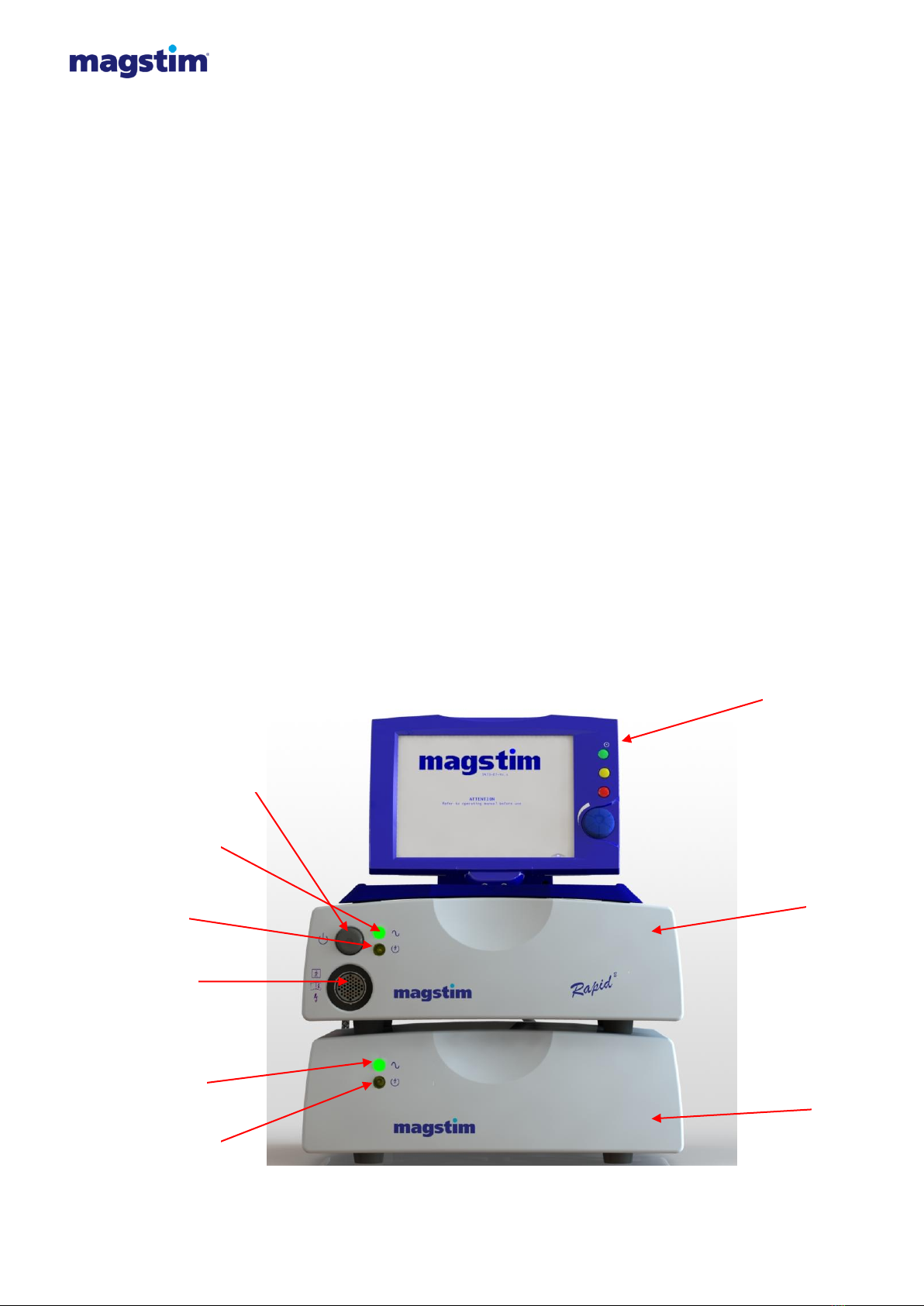
3.1 Magstim Standard Rapid² & Super Rapid² ................................................................. 5
3.2 Magstim Rapid² Plus¹............................................................................................. 10
3.3 Magstim Rapid² User Interface ............................................................................... 15
3.4 Accessories............................................................................................................ 17
Section 4 Operating Instructions...................................................................................... 19
4.1 Preparation............................................................................................................ 19
4.2 Rapid² Set-Up........................................................................................................ 19
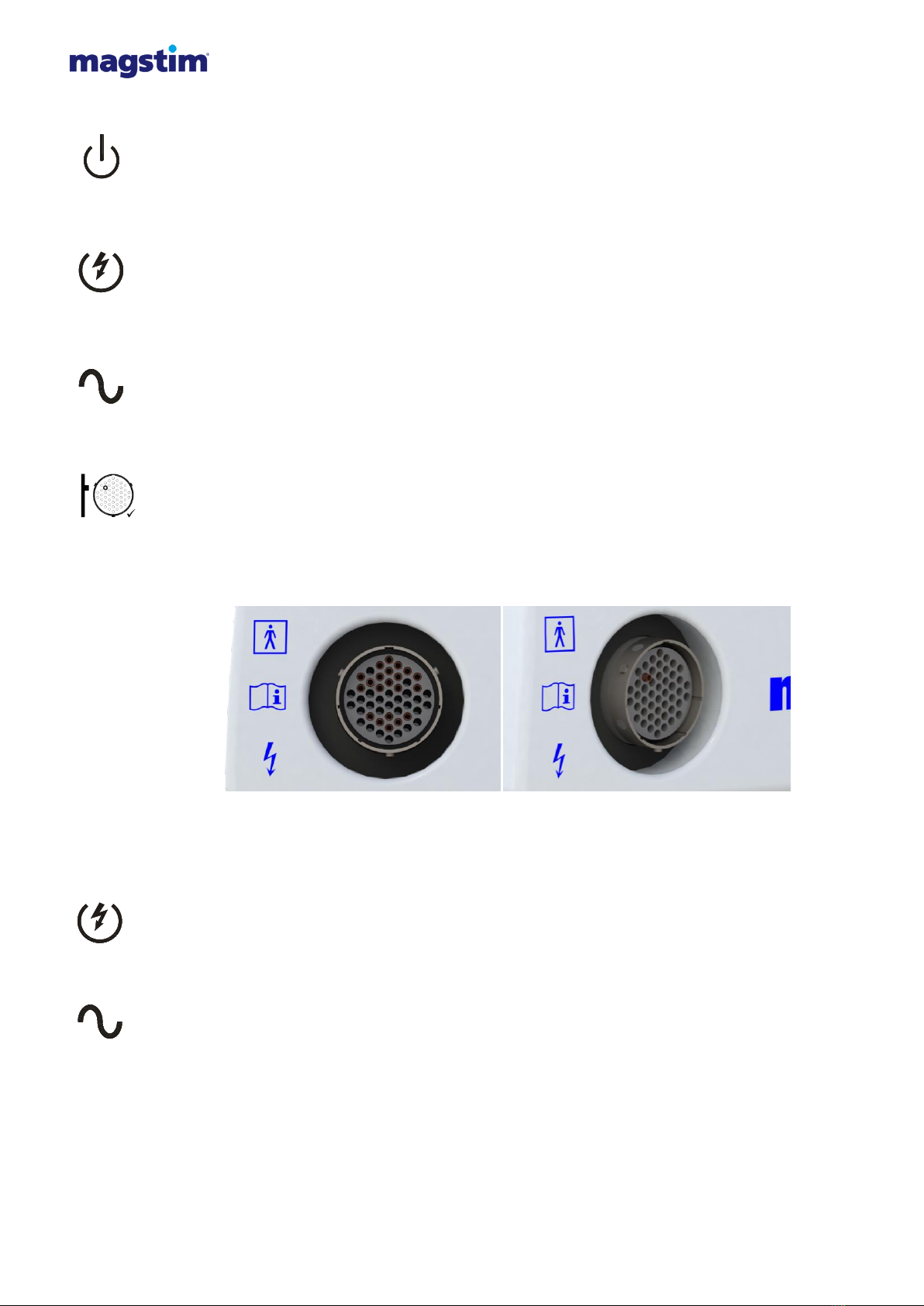
4.3 Connection of Accessories ...................................................................................... 22
4.4 Operation .............................................................................................................. 25
Section 5 Maintenance ................................................................................................... 45
5.1 User Maintenance and Calibration ........................................................................... 45
5.2 Technical Maintenance ........................................................................................... 45
5.3 Voltage Selection and Fuse Rating .......................................................................... 46
5.4 Cleaning and Disinfecting* ..................................................................................... 47
5.5 Servicing ............................................................................................................... 48
5.6 Device Lifetime ...................................................................................................... 48
5.7 Disposal ................................................................................................................ 48
Section 6 Specifications.................................................................................................. 49
6.1 General Specifications ............................................................................................ 49
6.2 Additional Safety Specifications............................................................................... 50
6.3 Technical Specifications.......................................................................................... 50
6.4 Output Safety, Repetition Rate of Stimulus .............................................................. 52
6.5 Environmental Conditions* ..................................................................................... 52
6.6Handling................................................................................................................ 53
6.7 Packing Instructions............................................................................................... 53
Section 7 Contact Details................................................................................................ 54
7.1 Product Enquiries................................................................................................... 54
7.2 Servicing Enquiries................................................................................................. 54
7.3 Sales Enquiries ...................................................................................................... 54
Appendix A –System Error Codes...................................................................................... 55
Appendix B –Trigger Input / Output .................................................................................... 57
Appendix C –SD Card File Details...................................................................................... 58
Appendix D –Power/Frequency.......................................................................................... 62
Appendix E –Coil compatibility........................................................................................... 65
Appendix F –EMC Emissions and Immunity........................................................................ 67

Magstim Rapid²
Operating Manual
© The Magstim Company Limited ii MOP03-EN-03
GUARANTEE
The Magstim Company Limited guarantees the effectiveness of both materials and workmanship for a
period of two years from the date of shipment; for the following products;
Magstim Rapid² - P/N: 3012-00
Single Power Supply Unit (PSU) - P/N: 3013-00
Dual Power Supply Unit (PSU) - P/N: 3014-00
Magstim Plus¹ Unit - P/N: 4040-00
Rapid² User Interface (UI) - P/N: 3022-00
Rapid² MEP Pod - P/N: 3526-00
For a period of one year from the date of shipment; for the following products;
Foot switch - P/N: 9525-01
The Capacitor is guaranteed for a period of two years from the date of shipment; or up to a maximum
of 1 million discharges; whichever is reached first.
The Magstim Company Ltd. reserves the right to perform guarantee services in its factory, at an
authorised repair station, or at the customer’s installation; at the discretion of the company.
The Magstim Company Ltd. guarantees to repair or replace defective equipment or parts, free of
charge within the guarantee period; provided that the said defects occur during normal service.
Replacement will be only at the company’s discretion where a repair is not possible and/or not
feasible.
Claims for damages during shipment must be filed promptly with the transportation company. All
correspondence concerning the equipment must specify the model name and/or number, as well as
the serial number, exactly as they appear on the equipment invoice.
Improper use, mishandling, tampering with, or operation of the equipment without following operating
instructions will void this guarantee and release The Magstim Company Limited from any further
obligations under this guarantee.
The Magstim Company Limited will only accept responsibility for effects on safety, reliability and
performance of the equipment if:
modifications or repairs are carried out by persons authorised by The Magstim Company
Limited;
the electrical installation of the relevant room complies with local regulations; and
the equipment is used in accordance with the instructions for use.

Magstim Rapid²
Operating Manual
© The Magstim Company Limited 1 MOP03-EN-03
SECTION 1 INTRODUCTION
1.1 Indications for Use
The Magstim Rapid2systems (Standard Rapid², Super Rapid² & Rapid² Plus¹) are magnetic
stimulators intended for non-invasive stimulation of neuromuscular tissue, by inducing small currents
in the tissue using a brief pulse of electromagnetic energy.
This method of stimulation enables deep, and otherwise inaccessible, nerves to be stimulated easily
and relatively painlessly. In addition, no skin preparation is required and stimulation can be achieved
through clothing.
The Magstim Rapid² systems are intended for use by, or under the supervision of, a medical
practitioner or investigator who has knowledge about the principles of TMS, physiology and potential
side effects of TMS.
The Magstim Rapid² systems are non-sterile reusable medical device intended for multi-patient use,
however is not intended to come into contact with the patient as this achieved through use of a
stimulating coil.
The Magstim Rapid² systems are intended to be stationary during use however, can be moved if
necessary when not in use.
The Rapid² systems are intended to be used on adults and children above the age of 2 years who do
not meet any of the contraindications listed in section 1.2. In all cases the subject is in a conscious
state.
USA Only: The Magstim Rapid² systems have not been cleared by the FDA for cortical stimulation.
Investigational uses require an IDE.
1.2 Contraindications
The Magstim Rapid² systems should not be;
•used on or in the vicinity of patients or users with cardiac demand pacemakers, implanted
medication pumps, cochlear devices, implanted defibrillators and/or implanted
neurostimulators
•used on or in the vicinity of patients with implanted metal objects
•used on patients where the skin in the area to be contacted is broken
•used on patients who suffer from multiple sclerosis
•used on those with large ischaemic scars
•used on pregnant women
•used on infants under the age of 2 years
•used on epileptic individuals
•used on those with a family history of convulsions
•used on individuals with brain lesions that could affect seizure threshold
•used on individuals suffering from multiple sclerosis
•used on individuals taking tricyclic antidepressants, neuroleptic agents or any other drug
that could lower seizure threshold,
•used on individuals suffering from sleep deprivation during rTMS procedures
•used on individuals with a heavy consumption of alcohol or those using epileptogenic
drugs
•Used on individuals with severe heart disease or with increased intracranial pressure be
used on those who have uncontrolled migraines
Magstim concurs with the recommendations given in the paper titled “Safety, ethical considerations,
and application guidelines for the use of transcranial magnetic stimulation in clinical practice and

Magstim Rapid²
Operating Manual
© The Magstim Company Limited 2 MOP03-EN-03
research” by Rossi et al (2009) and recommends the use of a standard questionnaire to screen
candidates prior to administering TMS.
1.3 Devices Covered
This document is applicable to the following device:
Magstim Rapid² System
This consists of:
Magstim Standard Rapid² System (P/N: 3004-00)
Magstim Super Rapid2System (P/N: 3005-00)
Magstim Rapid2Plus1System (P/N: 4100-00)
Rapid2UI Controller (P/N: 3022-00)
MEP Pod Assembly (P/N: 3526-00)
Footswitch (P/N: 9525-01)
and may also consist of the following optional parts:
Rapid² Printer Package (P/N: 3804-00)
If a Magstim Rapid² UI Controller is not used, a remote control will need to be used.
Note: Please also consult any labelling and information accompanying stimulating coils and other
accessories for safety and use information regarding these devices.
1.4 Frequently Used Functions
Frequently used functions as defined during Magstim’s usability process are identified with (*).
Frequently used functions are functions of the Rapid² that frequently involve user interaction.

Magstim Rapid²
Operating Manual
© The Magstim Company Limited 3 MOP03-EN-03
SECTION 2 WARNINGS AND PRECAUTIONS
Attention Consult Operating Manual: Consult the operating manual before using this device.
Ensure you are familiar with all sections of this operating manual prior to using the Rapid² system.
Operating Manual: Further information can be located in the operating manual. Where this
symbol is adjacent to a particular function on the Rapid² labelling, further information on this
function can be found in this operating manual.
Type BF Applied Part: Refer to Section 6.1 for further information.
Warning High Voltages: High voltages are present in the Magstim Rapid² system and
accessories during operation and for up to 20 minutes following operation. Therefore:
do not remove covers. Refer servicing to qualified personnel.
if there is any sign of external damage or if any parts are damp or wet, they
must not be used. Ensure that the System is not subject to conditions where
water/ liquid may be tipped on it, including the UI Controller.
ensure that the system is switched off prior to removing the HV cables at the
rear of the system*.
High Voltages: High voltages are present in the Magstim Rapid² system and accessories during
operation and for up to 20 minutes following operation. Therefore:
ensure that the system is disarmed prior to disconnecting the stimulating coil.
Coil Temperature: The system monitors the coil temperature and if this reaches 40°C, the
stimulator will be disabled. The coil surface temperature may continue to rise after this point;
therefore, the coil must be removed from the subject.
Rear Panel Outputs*: Only equipment that meets the relevant IEC standard should be connected
to the Magstim Rapid² system.
This connection must be configured in compliance with Clause 16 of IEC 60601-1:2005 with the
following interface voltage limitation: Max signalling voltage +5.3V; Max voltage with respect to
protective earth potential 30V peak
Magnetic Pulses: the system generates high intensity magnetic pulses through its coils, which
induce eddy currents in any conductive medium, such as the human body, nearby metallic objects
or electronic devices. Therefore, the system:
must not be used on, or in the vicinity of subjects with cardiac demand
pacemakers, implanted defibrillators, or other electronic or metallic implants;
must not be used in a position where the current can be induced in cables or
wires that are directly connected to the subject;
must not be used in the vicinity of objects that are sensitive to magnetic fields,
such as watches, credit cards and electronic equipment; and
must not be used when in contact with metallic objects, as these objects may be
propelled or damaged by the magnetic field of the coil.

Magstim Rapid²
Operating Manual
© The Magstim Company Limited 4 MOP03-EN-03
Damage: If there are any signs of damage to the Magstim Rapid² system, or if any parts are damp
or wet, the stimulator must not be used. If damaged, the Magstim Rapid² should be returned to the
Magstim Company Limited for servicing and repair (see Section 7.2 for contact details).
Explosive and Flammable Atmospheres: The Magstim Rapid² system and accessories must
not be used in an explosive atmosphere, around explosive gases or in the presence of flammable
anaesthetics.
Protective Earth: To avoid the risk of electric shock, the Magstim Rapid² system must only be
connected to supply mains with protective earth.
Note: Each of the mains connections for the Rapid2system must be made via separate,
permanent, mains outlets. On no account should a multi-way extension lead be used to connect
more than one mains connector to a single mains outlet.
Modification: No modification of this equipment is allowed.
Mains Leads: The Rapid2system must be used only with the supplied mains leads fitted with an
integral filter, as they are required to maintain the system’s compliance with EN 60601-1-2
regarding Electro-Magnetic emissions.
Earth Strap: The Rapid2system must only be used when fitted with the supplied earth straps,
this is to maintain the system’s compliance with EN 60601-1-2 regarding Electro-Magnetic
emissions. The strap is fitted between the stimulator and the power supply unit (PSU). In the case
of the Super Rapid2Plus1there are two earth straps. The first between the stimulator and the
Magstim Plus1, the second between the Magstim Plus1and power supply unit (PSU).
Discharge noise: when the magnetic pulse is delivered, a discharge click is produced that may
startle. The use of ear protection is recommended.
Ear protection must be worn by the patient when using the Rapid² Plus¹ system for cortical
stimulation at power levels above 70%.
Seizures: cortical magnetic stimulation runs the risk of inducing seizures. Magstim concurs with
the advice given in the paper titled “Safety, ethical considerations and application guidelines for
the use of TMS in clinical practice and research” by Rossi et al (2009) in respect to screening
candidates prior to administering TMS.
Safe levels of stimulation: For reasons of safety and reliability, if the system is set at 100%
power, the user must not exceed 250 stimuli per minute, or 4000 stimuli per hour or 24,000 stimuli
for every 24 hour period. This limitation is in addition to any other limitation imposed by the
dedicated controller, or heating effects on the stimulating coil and charger circuitry.
When stimulating at 100Hz, the Rapid² system must not be used for cortical stimulation,and is for
peripheral use only. For safety guidelines relating to transcranial stimulation, see Section 6.3 of
this Operating Manual.
Environmental Conditions*: The system must not be used or stored under environmental
conditions that fall outside those specified in Section 6.4 of this operating manual.
Stacking Limit: Please observe the stacking limit of the system. An assembled Rapid2system
can have a weight of up to 55kg. Ensure that the surface upon which the system is to be placed is
capable of supporting this weight. Failure to do so may result in injury or damage. The weight for
each individual module within the Rapid2system can be found in Section 6.5 of this manual.
MEP Pod: The MEP Pod is designed to be fitted to the Magstim Rapid² UI only. Do not attempt to
connect it to a computer, or any other equipment, with a similar connector. To do so could result
in electric shock/ burns to the patient at the site of electrode attachment. The MEP Pod connector
has a hole deliberately blocked to prevent incorrect connection.

Magstim Rapid²
Operating Manual
© The Magstim Company Limited 5 MOP03-EN-03
SECTION 3 PRODUCT DESCRIPTIONS
The Rapid2systems operate by inducing electrical currents in tissue using a non-invasive stimulating
coil at frequencies of up to 100Hz. The stimulating coil is placed near the intended site of stimulation
and trigger pulses initiate brief magnetic pulses. The magnetic fields can pass through clothing, tissue
and bone to reach otherwise inaccessible areas. One feature of magnetic stimulation is that it is less
likely to stimulate pain fibres at the skin surface, reducing the discomfort when compared with
conventional electrical stimulation. Magstim Rapid² magnetic stimulators combine stimulation
frequencies from 1Hz to 100Hz with a touch screen interface which controls every aspect of the
stimulator's control and operation.
3.1 Magstim Standard Rapid² & Super Rapid²
The Standard Rapid² consists of a Single PSU, Rapid² Stimulator, Rapid² UI and can use an optional
Rapid² MEP Pod for recording motor evoked potentials.
The Super Rapid² uses the same modules with the exception of the Single PSU which is replaced by
the Dual PSU. This allows stimulation to occur at higher frequencies for a given power level to be
delivered to the patient.
3.1.1 Front view
The front panel, shown below, allows control of the Standard Rapid² and Super Rapid² and provides
the connection for the stimulating coil.
All operating functions described in this section assume that the mains power switch, located on the
rear panel, is switched on.
Figure 3.1: Detailed front panel of Standard Rapid² and Super Rapid²
(3)
(1)
(6)
(4)
(5)
(7)
(8)
(9)
(2)

Magstim Rapid²
Operating Manual
© The Magstim Company Limited 6 MOP03-EN-03
3.1.1.1 On/Off/Standby* (1)
This switch toggles the operational state of the Rapid2.
3.1.1.2 Armed Indicator* (2)
The armed indicator illuminates when the unit is armed and high voltages are present on the system.
3.1.1.3 Power Indicator* (3)
The power indicator flashes when the Magstim Rapid² is in standby, and illuminates when the Magstim
Rapid² is on.
3.1.1.4 Coil Output Socket* (4)
This socket is used to connect the stimulating coil to the Magstim Rapid².
Note: It is normal for the pin indicated on the label to protrude from the coil socket. This is an
intentional design feature.
Figure 3.2: Coil output socket front view Figure 3.3: Coil output socket angled view
3.1.1.5 Armed/Fault Indicator* (5)
This LED is continuously illuminated when the Magstim Rapid2is armed and high voltages are present
on the system. This LED turns RED when a fault is detected in the PSU.
3.1.1.6 PSU Power Status Indicator* (6)
The PSU power indicator is OFF when the system is in standby or OFF. It is continuously illuminated
when the system is on.
3.1.1.7 Rapid² UI (7)
This is the interface by which the user controls the stimulator. See Section 3.3 for further details.

Magstim Rapid²
Operating Manual
© The Magstim Company Limited 7 MOP03-EN-03
3.1.1.8 Mainframe (8)
This Mainframe contains the circuitry that allows the stimulator to deliver energy as specified using the
UI.
3.1.1.9 Power Supply Unit (PSU) (9)
The PSU contains the electronic circuitry that powers the stimulator.
3.1.2 Rear view
Figure 3.4: Detailed rear panel of Super Rapid²
Note: The only difference between connections on the Standard Rapid² compared to the Super Rapid²
is the additional mains inlet on the left hand side of the PSU.
Note: 115V units are identical in appearance to the 230V units, with the exception of the
voltage/power rating labels sited to the rear
3.1.2.1 UI Cable* (1)
The UI cable connects the Rapid² UI to the Rapid² mainframe.
(5)
(1)
(2)
(3)
(4)
(6)
(8)
(9)
(10)
(11)
(12)
(13)
(7)

Magstim Rapid²
Operating Manual
© The Magstim Company Limited 8 MOP03-EN-03
3.1.2.2 Mains Power Switch* (2)
The Power switch allows the power supplying the unit to be switched on (labelled I) or off (labelled O).
3.1.2.3 Fuse Access and Voltage Selector* (3)
Access for fuse replacement and changing the voltage selector setting. See Section 5.3 for further
details.
3.1.2.4 Power Entry Module* (4)
Power input port on the Rapid² mainframe.
3.1.2.5 Link Lead* (5)
The 10A link lead provides powers to the mainframe from the PSU.
3.1.2.6 HV Cable* (6)
The HV cable is used to interconnect the high voltage power between the mainframe and the PSU.
3.1.2.7 Mains input to PSU (Super Rapid² Only)* (7)
Mains input port on the Super Rapid² PSU.
3.1.2.8 Isolated Trigger Port* (8)
This 26 way D-Type connector is situated on the rear of the UI and has three rows of pins. It provides
trigger input and output signals. (see Appendix B).
3.1.2.9 Foot Switch Pneumatic Socket* (9)
This socket is used to connect the pneumatic foot switch to the Magstim Rapid² system. The foot
switch can be used to trigger the instrument when one of the trigger buttons located on the coil is also
pressed. The instrument will continuously charge and discharge if the trigger buttons are pressed and
held.

Magstim Rapid²
Operating Manual
© The Magstim Company Limited 9 MOP03-EN-03
3.1.2.10 Cooling Fan Outlet (10)
With the Magstim Rapid² system turned on, air is drawn through slots at the bottom of the instrument
and expelled through the fan outlet. There should be no obstructions placed closer than 50mm to the
fan outlet.
3.1.2.11 HV Power Entry Socket (11)
The HV cable is connected to this connector to interconnect the high voltage power between the
mainframe and the PSU.
Note: High voltage can be present on this connector.
3.1.2.12 Earth Strap (12)
The Rapid2system must only be used when fitted with the supplied earth straps, this is to maintain the
system’s compliance with EN 60601-1-2 regarding Electro-Magnetic emissions. The strap is fitted
between the stimulator and the PSU.
3.1.2.13 Mains input to PSU* (13)
Mains input port on the Standard Rapid² PSU and Super Rapid² PSU.

Magstim Rapid²
Operating Manual
© The Magstim Company Limited 10 MOP03-EN-03
3.2 Magstim Rapid² Plus¹
The Rapid² Plus¹ uses the same modules as the Super Rapid² with the addition of the Plus¹ module
which has an additional PSU. This allows stimulation to occur at higher frequencies for a given power
level to be delivered to the patient.
3.2.1 Front view
The front panel, shown below, allows control of the Standard Rapid² Plus¹ and provides the
connection for the stimulating coil.
All operating functions described in this section assume that the mains power switch, located on the
rear panel, is switched on
Figure 3.5: Detailed front panel of Rapid² Plus¹.
3.2.1.1 On/Off/Standby* (1)
This switch toggles the operational state of the Rapid2.
3.2.1.2 Armed Indicator* (2)
The armed indicator illuminates when the unit is armed and high voltages are present on the system.
(1)
(2)
(3)
(4)
(6)
(5)
(9)
(7)
(8)
(10)
(11)
(12)

Magstim Rapid²
Operating Manual
© The Magstim Company Limited 11 MOP03-EN-03
3.2.1.3 Power Indicator* (3)
The power indicator flashes when the Magstim Rapid² is in standby, and illuminates when the Magstim
Rapid² is on.
3.2.1.4 Coil Output Socket* (4)
This socket is used to connect the stimulating coil to the Magstim Rapid². Note that the unit
Note: It is normal for the pin indicated on the label to protrude from the coil socket. This is an
intentional design feature.
Figure 3.6: Coil output socket front view Figure 3.7: Coil output socket angled view
3.2.1.5 Armed/Fault Indicator* (5)
This LED is continuously illuminated when the Magstim Rapid2is armed and high voltages are present
on the system. This LED turns RED when a fault is detected in the PSU.
3.2.1.6 PSU Power Status Indicator* (6)
The PSU power indicator is OFF when the system is in standby or OFF. It is continuously illuminated
when the system is on.
3.2.1.7 Power Indicator* (7)
This LED is continuously illuminated green when the Plus1module is powered on.
3.2.1.8 Status/Fault Indicator* (8)
This LED is continuously illuminated green when system is operating correctly. This LED turns RED
when a fault has been detected in either the Dual PSU or Plus1Module.
3.2.1.9 Rapid² UI (9)
This is the interface by which the user controls the stimulator. See Section 3.3 for further details.

Magstim Rapid²
Operating Manual
© The Magstim Company Limited 12 MOP03-EN-03
3.2.1.10 Main Frame (10)
This Mainframe contains the circuitry that allows the stimulator to deliver energy as specified using the
UI.
3.2.1.11 Plus1Module (11)
This module is a combination of PSU and control circuitry that allows additional performance
compared to that of a Standard or Super Rapid2system.
3.2.1.12 Dual Power Supply Unit (PSU) (12)
The dual PSU contains the electronic circuitry that powers the stimulator.
3.2.2 Rear view
Figure 3.8: Detailed rear panel of Rapid² Plus¹.
Note: 115V units are identical in appearance to the 230V units, with the exception of the
voltage/power rating labels sited to the rear
(2)
(3)
(4)
(5)
(6)
(13)
(15)
(9)
(10)
(11)
(12)
(8)
(14)
(1)
(7)

Magstim Rapid²
Operating Manual
© The Magstim Company Limited 13 MOP03-EN-03
3.2.2.1 UI Cable* (1)
The UI cable connects the Rapid² UI to the Rapid² mainframe.
3.2.2.2 Mains Power Switch* (2)
The Power switch allows the power supplying the unit to be switched on (labelled I) or off (labelled O).
3.2.2.3 Fuse Access and Voltage Selector* (3)
Access for fuse replacement and changing the voltage selector setting. See section 5.3 for further
details.
3.2.2.4 Power Entry Module* (4)
Power input port on the Rapid² mainframe and Plus¹ module.
3.2.2.5 Link Lead* (5)
The 10A link lead provides powers to the Plus¹ from the PSU and to the mainframe from the Plus¹.
3.2.2.6 Plus¹ Mains Power Switch* (6)
The Power switch allows the power supplying the Plus¹ module unit to be switched on (labelled I) or
off (labelled O).
3.2.2.7 Plus¹ HV Power Output Socket* (7)
This connector is the HV output on the Plus¹ which interconnects the high voltage power between the
mainframe and the Plus ¹ module.
Note: High voltage can be present on this connector.
3.2.2.8 HV Cable* (8)
The HV cable is used to interconnect high voltage power between the mainframe, Plus¹ and the PSU.
3.2.2.9 Isolated Trigger Port* (9)
This 26 way D-Type connector is situated on the rear of the UI and has three rows of pins. It provides
trigger input and output signals. (see Appendix B).

Magstim Rapid²
Operating Manual
© The Magstim Company Limited 14 MOP03-EN-03
3.2.2.10 Foot Switch Pneumatic Socket* (10)
This socket is used to connect the pneumatic foot switch to the Magstim Rapid² system. The foot
switch can be used to trigger the instrument when one of the trigger buttons located on the coil is also
pressed. The instrument will continuously charge and discharge if the trigger buttons are pressed and
held.
3.2.2.11 Cooling Fan Outlet (11)
With the Magstim Rapid² system turned on, air is drawn through slots at the bottom of the instrument
and expelled through the fan outlet. There should be no obstructions placed closer than 50mm to the
fan outlet.
3.2.2.12 HV Power Entry Socket (12)
The HV cable is connected to this connector to interconnect the high voltage power between the
mainframe and the PSU.
Note: High voltage can be present on this connector.
3.2.2.13 Earth Strap (13)
The Rapid2system must only be used when fitted with the supplied earth straps, this is to maintain the
system’s compliance with EN 60601-1-2 regarding Electro-Magnetic emissions. The strap is fitted
between the stimulator and the Plus¹ unit and between the Plus¹ unit and the PSU.
3.2.2.14 Plus¹ HV Power Input Socket* (7)
This connector is the HV input on the Plus¹ which interconnects the high voltage power between the
PSU and the Plus ¹ module.
Note: High voltage can be present on this connector.
3.2.2.15 Mains input to PSU and Plus¹* (15)
Mains input port on the PSU and Plus¹ module.

Magstim Rapid²
Operating Manual
© The Magstim Company Limited 15 MOP03-EN-03
3.3 Magstim Rapid² User Interface
The Rapid² UI is a touch screen user interface by which the user controls the Magstim Rapid² system.
3.3.1 Front view
All operating functions described in this section assume that the mains power switch, located on the
rear panel of the Rapid², is switched on
Figure 3.9: Detailed front panel of Rapid² UI.
3.3.1.1 Run Button* (1)
The Magstim Rapid² system can be put into the armed mode by momentarily pushing the Green RUN
button. This can only be achieved if the stimulating coil is connected to the coil output socket.
3.3.1.2 Trigger Button* (2)
The Magstim Rapid² can be triggered to deliver the protocol by pressing the yellow TRIGGER button.
Note: It may be necessary to also activate the coil interlock buttons with some Magstim stimulating
coils in order to trigger the system.
3.3.1.3 System Stop Button* (3)
The Magstim Rapid² can be disarmed and put into a safe state by pushing the red STOP button. In
this mode the system will discharge internally.
3.3.1.4 Output Control* (4)
This control allows the user to change the screen-selected parameter to the desired value. It is
therefore used to alter screen settings as well as changing the power output of the stimulator.
(1)
(2)
(3)
(4)
(5)

Magstim Rapid²
Operating Manual
© The Magstim Company Limited 16 MOP03-EN-03
3.3.1.5 Touch-Sensitive Screen/ System Display * (5)
All selections are made via the touch-screen. To select, touch the centre of the button symbol next to
the desired menu option. Do not press hard, or use a sharp or pointed object to make the selection,
as this may damage the touch screen.
In the set-up screens, all selectable items are coloured in pale blue; white items are non-selectable.
The Rotary Control Knob can only be used to change parameters already selected. Details regarding
the contents and operation of the UI Screens are given in Sections 4.4
Note: If the UI is not used for 30 minutes it will go into a standby condition. In standby, the screen will
appear blank and the blue LED in the upper right corner of the front bezel will pulse. Touch the screen
to restore the UI.
3.3.2 Rear view
Figure 3.10: Detailed front panel of Rapid² UI.
3.3.2.1 Printer Connection* (1)
The Printer is attached to the User Interface via an Optical/RS232 Interface Cable which slides into
place on the right hand side at the rear of the UI.
3.3.2.2 25 Way D-Type Connector* (2)
This connector is situated on the rear of the UI, and has 2 rows of pins. The connector links the UI to
the Magstim Rapid2as shown in figures 3.4 and 3.8.
3.3.2.3 SD Card Insertion Point* (3)
This socket is situated on the rear of the left hand side panel of the UI. This allows connection of an
SD Card. This removable memory storage facility enables transfer of data between the UI and
external devices, such as PCs.
Non-Selectable
Window
Selectable
Window
Button
(1)
(2)
(3)
(4)
(5)
(6)
(7)

Magstim Rapid²
Operating Manual
© The Magstim Company Limited 17 MOP03-EN-03
3.3.2.4 15 Way D-Type Connector* (4)
This connector is situated on the rear of the UI behind the removable cover. It is designed to accept
the Motor Evoked Potential (MEP) pod, available as a separate item. It has type BF connection.
3.3.2.5 DC Power Jack* (5)
The DC Power Jack is situated on the rear of the UI. This connector allows an external 24V, 750mA
DC power supply to be attached. A suitable medical grade supply must be used, conforming to IEC
60601-1. This is NOT required when the UI is connected to the Magstim Rapid2.
3.3.2.6 Batteries* (6)
The battery compartment is accessed from the base of the UI. The batteries are required to maintain
configuration details such as time and date following power cycles.
3.3.2.7 26 Way D Type Connector* (7)
This connector is situated on the rear of the UI, and has 3 rows of pins. It provides trigger input and
output signals (see Appendix B).
3.4 Accessories
The use of the correct accessories is essential to the functioning of the Magstim Rapid². The Magstim
Company Limited cannot guarantee the instrument’s performance unless accessories used are
obtained from The Magstim Company Limited. Only Magstim accessories purchased from The
Magstim Company Limited should be used with the Magstim Rapid².
Note: The Magstim Rapid² system should only be powered using the power leads supplied by The
Magstim Company Ltd.
3.4.1 Stimulating coils
A range of stimulating coils is available for use with the Magstim range of products. For more details,
please contact the Sales department. Contact details are shown in Section 7.3.
3.4.2 MEP Pod
NOTE. The Rapid2must be switched off before connecting or disconnecting the MEP Pod.
The Motor Evoked Potential (MEP) Pod is an optional component which allows the user to capture
EMG signals and display them on the UI. 2 channels are available. The MEP Pod should be mounted
Other manuals for RAPID2
2
Table of contents
Other MAGSTIM Medical Equipment manuals

MAGSTIM
MAGSTIM BiStim2 User manual

MAGSTIM
MAGSTIM MOP11-EN User manual

MAGSTIM
MAGSTIM 200 2 User manual

MAGSTIM
MAGSTIM NEUROSIGN V4 User manual

MAGSTIM
MAGSTIM BiStim2 User manual

MAGSTIM
MAGSTIM 3190-00 User manual

MAGSTIM
MAGSTIM 2002 User manual

MAGSTIM
MAGSTIM RAPID2 User manual

MAGSTIM
MAGSTIM NEUROSIGN V4 User manual
Popular Medical Equipment manuals by other brands

New Life Radiology
New Life Radiology DIGISMILE manual

Gima
Gima 30553 Instructions for use

Norditalia
Norditalia Calor Standard operating manual

AutoMedx
AutoMedx SAVe II Operating and maintaining

Merit Medical
Merit Medical ONE Snare Endovascular Microsnare System Instructions for use

medi
medi 2 in 1 Instructions for use