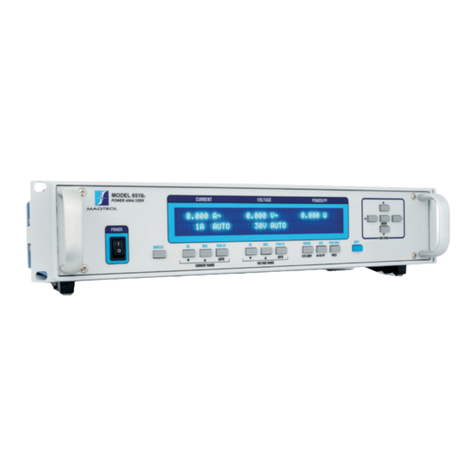
Magtrol 6530 User manual

Model 6530
Three-Phase
Power Analyzer
User’s Manual

1st Edition, Rev. D – September 2003
While every precaution has been exercised in the compilation of this document to
ensure the accuracy of its contents, Magtrol, Inc. assumes no responsibility for errors
or omissions. Additionally, no liability is assumed for any damages that may result
from the use of the information contained within this publication.
COPYRIGHT
Copyright ©2001-2003 Magtrol, Inc. All rights reserved.
Copying or reproduction of all or any part of the contents of this manual without the
express permission of Magtrol is strictly prohibited.
TRADEMARKS
LabVIEW™ is a trademark of National Instruments Corporation.
National Instruments™ is a trademark of National Instruments Corporation.
Windows® is a registered trademark of Microsoft Corporation.

i
1. Make sure that all Magtrol dynamometers and electronic products are earth-grounded, to ensure
personal safety and proper operation.
2. Securely ground the 6530 Power Analyzer case by connecting a good earth ground at the
ground stud located on the rear panel of the unit. Use a number 12 AWG, or larger wire.
3. Check line voltage before operating.
4. Make sure that dynamometers and motors under test are equipped with appropriate safety
guards.
Safety Precautions
STOP
STOP

ii
The contents of this manual are subject to change without prior notice. Should revisions be necessary, updates to all
Magtrol User’s Manuals can be found at Magtrol’s web site at www.magtrol.com/support/manuals.htm.
Please compare the date of this manual with the revision date on the web site, then refer to the manual’s Table of
Revisions for any changes/updates that have been made since this edition.
REVISION DATE
1st Edition, Revision D – September 2003
TABLE OF REVISIONS
Revisions To This Manual
etaD noitidE egnahC )s(noitceS
30/03/90D.veR,noitidEts1.deriuqerputeson-egatloveniL:noitcerroC 1.1.3
30/91/60C.veR,noitidEts1 .e
domegarevaraelc/tratsotCIdnaSIsdnammocnoitarugifnocdeddA 1.6.5
30/91/60C.veR,noitidEts1 .seulavdeyalpside
veirterotEVAOdnammoctuptuoataddeddA 2.6.5
20/91/60B.veR,noitidEts1 .teehsatadotnoitamrofninoitpotuptuogol
anadeddA 3.1
20/02/50A.veR,noitidEts1 cihparguneMputeSrotcaFelacSrosneSlanretxEniVm/AotA/VmdegnahC 2.3.3.3
20/02/50A.veR,noitidEts1 edocdnammoc>rotanimret<2m1ESfoegnareulavdnastinudetadpU 1.6.5
10/62/11noitidEts1 .
ssecorpnoitarbilaccisabfo)egnarpmagnittes(31petsdetadpU 4.6
10/62/11noitidEts1 .elpmaxETOninoitisoPataDfo
dneot"ycneuqerF"deddA 1.4.5
10/62/11noitidEts1
0156eht,tinuetarapesA.tnemurtsniesahp-eerhtayliramirpsitcu
dorP
e
sah,
tnemerusaemesahp-elgniseriuqerylnoohwsresurofdepolevedneeb
egnahctcudorpsihttcelferotdetadpuneebsa
hlaunam0356ehT.seitilibapac
0156adna e.detaercneebsahlaunam
2.1
3.1
10/50/11launaMyranimilerP .edocdnammoc>r
otanimret<mFMfoseulavdetadpU 1.6.5

iii
Table of Contents
SAFETY PRECAUTIONS ......................................................................................................................... i
REVISIONS TO THIS MANUAL............................................................................................................... ii
REVISION DATE .................................................................................................................................................................ii
TABLE OF REVISIONS ......................................................................................................................................................ii
TABLE OF CONTENTS ......................................................................................................................... iii
TABLE OF FIGURES ......................................................................................................................................................... vi
PREFACE .............................................................................................................................................. vii
PURPOSE OF THIS MANUAL ........................................................................................................................................ vii
WHO SHOULD USE THIS MANUAL ............................................................................................................................. vii
MANUAL ORGANIZATION ............................................................................................................................................ vii
CONVENTIONS USED IN THIS MANUAL .................................................................................................................. viii
1. INTRODUCTION ................................................................................................................................ 1
1.1 UNPACKING YOUR 6530 POWER ANALYZER ....................................................................................................... 1
1.2 NEW FEATURES OF THE 6530 POWER ANALYZER .............................................................................................. 1
1.3 DATA SHEET ................................................................................................................................................................ 2
2. CONTROLS ........................................................................................................................................ 5
2.1 FRONT PANEL ............................................................................................................................................................. 5
2.2 FRONT PANEL CONTROLS AND BUTTONS .......................................................................................................... 5
2.2.1 Enabling Secondary Functions ........................................................................................................................ 6
2.2.2 Using Front Panel Controls and Buttons ......................................................................................................... 6
2.3 VACUUM FLUORESCENT DISPLAY (VFD) ............................................................................................................ 8
2.3.1 Contrast Settings .............................................................................................................................................. 8
2.3.2 Display Guide .................................................................................................................................................. 9
2.4 REAR PANEL ............................................................................................................................................................. 10
2.5 REAR PANEL INPUTS AND OUTPUTS .................................................................................................................. 10
3. INSTALLATION/CONFIGURATION ................................................................................................. 13
3.1 POWERING UP THE 6530 ......................................................................................................................................... 13
3.1.1 Line Voltage ................................................................................................................................................... 13
3.1.2 Self-Test ......................................................................................................................................................... 13
3.1.3 Main Menu .................................................................................................................................................... 14
3.2 PROTECTING YOUR 6530 ........................................................................................................................................ 15
3.2.1 Transient Overloads ....................................................................................................................................... 15
3.2.2 Current Overload ........................................................................................................................................... 15
3.2.3 Surge Protection ............................................................................................................................................. 15
3.2.4 Circuit Breakers ............................................................................................................................................. 16
3.3 TESTING INSTRUMENTATION SETUP .................................................................................................................. 17
3.3.1 Wiring Mode .................................................................................................................................................. 17
3.3.2 Measurement Filter ........................................................................................................................................ 23
3.3.3 External Sensor .............................................................................................................................................. 24
3.3.4 Amp Scaling .................................................................................................................................................. 26
3.3.5 Volts Scaling .................................................................................................................................................. 28
3.3.6 Phase Setup .................................................................................................................................................... 29
3.3.7 Special Functions ........................................................................................................................................... 30

iv
Magtrol Model 6530 Three-Phase Power AnalyzerTable of Contents
4. OPERATING PRINCIPLES............................................................................................................... 32
4.1 ANALOG PROCESSING ............................................................................................................................................ 32
4.1.1 Volts ............................................................................................................................................................... 32
4.1.2 Amps .............................................................................................................................................................. 33
4.1.3 External Shunt ............................................................................................................................................... 34
4.2 DIGITAL PROCESSING ............................................................................................................................................. 34
4.2.1 AC Details ...................................................................................................................................................... 35
4.2.2 DC Details ..................................................................................................................................................... 37
4.2.3 Round-Off Error ............................................................................................................................................ 39
4.3 MEASUREMENT MODES ........................................................................................................................................ 39
4.3.1 Peak................................................................................................................................................................ 39
4.3.2 Peak Hold / Inrush Current ............................................................................................................................ 40
4.3.3 DC .................................................................................................................................................................. 40
4.3.4 RMS ............................................................................................................................................................... 41
4.3.5 Crest Factor .................................................................................................................................................... 41
4.4 MEASUREMENT METHODS ................................................................................................................................... 41
4.4.1 Cycle-by-Cycle Mode .................................................................................................................................... 41
4.4.2 Continuous Mode .......................................................................................................................................... 41
5. COMPUTER CONTROLLED OPERATION ...................................................................................... 42
5.1 ABOUT THE GPIB INTERFACE ............................................................................................................................... 42
5.1.1 Installing the GPIB/IEEE-488 Connector Cable ........................................................................................... 42
5.1.2 Changing the GPIB Primary Address ............................................................................................................ 42
5.2 ABOUT THE RS-232 INTERFACE ............................................................................................................................ 43
5.2.1 Connection ..................................................................................................................................................... 43
5.2.2 Communication Parameters ........................................................................................................................... 44
5.2.3 Baud Rate....................................................................................................................................................... 44
5.3 CHECKING THE 6530-TO-PC CONNECTION ........................................................................................................ 44
5.4 DATA FORMAT .......................................................................................................................................................... 45
5.4.1 OT Example ................................................................................................................................................... 45
5.4.2 OE Example ................................................................................................................................................... 46
5.4.3 OA/OV/OW/OF Example .............................................................................................................................. 46
5.5 PROGRAMMING ........................................................................................................................................................ 46
5.5.1 Data Termination Characters ......................................................................................................................... 46
5.6 6530 COMMUNICATION COMMANDS .................................................................................................................. 47
5.6.1 Configuration Commands .............................................................................................................................. 47
5.6.2 Data Output Commands ................................................................................................................................ 50
6. CALIBRATION .................................................................................................................................. 51
6.1 CLOSED-BOX CALIBRATION ................................................................................................................................. 51
6.2 CALIBRATION SCHEDULE ..................................................................................................................................... 51
6.3 CALIBRATION COMMANDS ................................................................................................................................... 51
6.4 BASIC CALIBRATION PROCESS ............................................................................................................................ 52
7. OPTIONAL FEATURES .................................................................................................................... 54
7.1 ANALOG OUTPUTS .................................................................................................................................................. 54
7.1.1 Specifications ................................................................................................................................................. 54
7.1.2 Channel Assignments .................................................................................................................................... 54
7.1.3 Hardware Connection .................................................................................................................................... 55
7.1.4 Software Configuration ................................................................................................................................. 55
7.1.5 Calibration ..................................................................................................................................................... 56

v
Magtrol Model 6530 Three-Phase Power Analyzer Table of Contents
8. TROUBLESHOOTING ...................................................................................................................... 58
APPENDIX A: SCHEMATICS ............................................................................................................... 59
A.1 MAIN BOARD - DSP, RAM, FLASH ........................................................................................................................ 59
A.2 MAIN BOARD - INPUT/OUTPUT, GPIB, RS-232 ................................................................................................... 60
A.3 MAIN BOARD - FPGA ............................................................................................................................................... 61
A.4 INPUT MODULE - CURRENT .................................................................................................................................. 62
A.5 INPUT MODULE - VOLTAGE ................................................................................................................................... 63
A.6 KEY PAD ..................................................................................................................................................................... 64
A.7 ANALOG OUTPUT .................................................................................................................................................... 65
GLOSSARY ........................................................................................................................................... 69
INDEX .................................................................................................................................................... 70
MAGTROL LIMITED WARRANTY ........................................................................................................72

vi
Magtrol Model 6530 Three-Phase Power AnalyzerTable of Contents
TABLE OF FIGURES
CHAPTER 2
Figure 2–1 Front Panel ............................................................................................................................................. 5
Figure 2–2 Secondary Function Menu ..................................................................................................................... 6
Figure 2–3 Device Setup Menu ................................................................................................................................. 9
Figure 2–4 Rear Panel ............................................................................................................................................ 10
Figure 2–5 Input Module ........................................................................................................................................ 10
Figure 2–6 RS-232C Interface ................................................................................................................................ 11
Figure 2–7 GPIB/IEEE-488 Interface .................................................................................................................... 11
CHAPTER 3
Figure 3–1 Program Download Display ................................................................................................................. 13
Figure 3–2 Title Display ......................................................................................................................................... 13
Figure 3–3 Revision Display ................................................................................................................................... 14
Figure 3–4 Phase Main Menu ................................................................................................................................. 14
Figure 3–5 Summation Main Menu ........................................................................................................................ 14
Figure 3–6 Custom Main Menu .............................................................................................................................. 15
Figure 3–7 Transient Voltage Suppression .............................................................................................................. 16
Figure 3–8 Single-Phase, Two-Wire Wiring Schematic .......................................................................................... 18
Figure 3–9 Single-Phase, Two-Wire Wiring Connection ........................................................................................ 18
Figure 3-10 Single-Phase, Three-Wire Wiring Schematic ........................................................................................ 19
Figure 3–11 Single-Phase, Three-Wire Wiring Connection ...................................................................................... 19
Figure 3–12 Three-Phase, Three-Wire Wiring Schematic ......................................................................................... 20
Figure 3–13 Three-Phase, Three-Wire Wiring Connection ....................................................................................... 20
Figure 3–14 Three-Phase, Four-Wire Wiring Schematic .......................................................................................... 21
Figure 3–15 Three-Phase, Four-Wire Wiring Connection ........................................................................................ 21
Figure 3–16 Three-Voltage, Three-Ampere Wiring Schematic .................................................................................. 22
Figure 3–17 Three-Voltage, Three-Ampere Wiring Connection ................................................................................ 22
Figure 3–18 Sensor Substitution Wiring Schematic .................................................................................................. 24
Figure 3–19 Sensor Substitution Wiring Connection................................................................................................ 24
Figure 3–20 External Sensor Scale Factor Setup Menu ........................................................................................... 25
Figure 3–21 Current/Potential Transformer Connection .......................................................................................... 26
Figure 3–22 Amp Scaling Setup Menu ...................................................................................................................... 26
Figure 3–23 Amp/Volt Scaling Activated .................................................................................................................. 27
Figure 3–24 Volt Scaling Setup Menu ....................................................................................................................... 28
Figure 3–25 Cycle-by-Cycle Mode ........................................................................................................................... 29
Figure 3–26 Hold Mode ............................................................................................................................................ 30
Figure 3–27 Average Mode ....................................................................................................................................... 30
Figure 3–28 Peak Hold Clear Display ...................................................................................................................... 31
Figure 3–29 Custom Display .................................................................................................................................... 31
CHAPTER 4
Figure 4-1 Peak Example ....................................................................................................................................... 39
Figure 4–2 Peak Hold/Inrush Current Example ..................................................................................................... 40
Figure 4–3 Crest Factor Example ........................................................................................................................... 41
CHAPTER 5
Figure 5–1 GPIB Installation ................................................................................................................................. 42
Figure 5–2 GPIB Address Setup Menu ................................................................................................................... 43
Figure 5–3 RS-232 Interface ................................................................................................................................... 43
Figure 5–4 Cable Connection Using Null Modem ................................................................................................. 43
Figure 5–5 RS-232 Baud Rate Setup Menu ............................................................................................................ 44
CHAPTER 6
Figure 6–1 Calibration/Verification Test Setup ...................................................................................................... 52
Figure 6–2 Calibration Mode Enabled ................................................................................................................... 52
CHAPTER 7
Figure 7–1 Analog Output ...................................................................................................................................... 54
Figure 7–2 Analog Output Setup Menu .................................................................................................................. 55

vii
PURPOSE OF THIS MANUAL
This manual contains all the information required for the installation and general use of the Model
6530 Power Analyzer. To achieve maximum capability and ensure proper use of the instrument,
please read this manual in its entirety before operating. Keep the manual in a safe place for quick
reference whenever a question should arise.
WHO SHOULD USE THIS MANUAL
This manual is intended for those operators who are planning to use the Model 6530 PowerAnalyzer
for power measurement purposes either as a stand-alone instrument or in conjunction with any
Magtrol Hysteresis, Eddy-Current or Powder Brake Dynamometer, any Magtrol Dynamometer
Controller and M-TEST Motor Testing Software.
MANUAL ORGANIZATION
This section gives an overview of the structure of the manual and the information contained within
it. Some information has been deliberately repeated in different sections of the document to minimize
cross-referencing and to facilitate understanding through reiteration.
The structure of the manual is as follows:
Chapter 1: INTRODUCTION - Contains the technical data sheet for the 6530 Power Analyzer,
which describes the unit and provides its mechanical and electrical characteristics.
Chapter 2: CONTROLS - Description of the elements located on the front and rear panels of
the unit.
Chapter 3: INSTALLATION/CONFIGURATION - Provides information needed for setup of
the 6530 including wiring mode, measurement filter, external sensor, amp scaling
and volt scaling along with phase setup instructions and special functions available.
Chapter 4: OPERATING PRINCIPLES - Information pertaining to theory of operation
including analog processing, digital processing, measurement modes and
measurement methods.
Chapter 5: COMPUTER CONTROLLED OPERATION - How to run a test when the 6530 is
used with a PC. Includes information on IEEE-488 and RS-232 Interface, data
format, programming and command set.
Chapter 6: CALIBRATION - Provides recommended calibration schedules along with step-
by-step instructions for the calibration procedure.
Chapter 7: OPTIONAL FEATURES - Provides information regarding various optional features
available with the 6530 including analog outputs.
Chapter 8: TROUBLESHOOTING - Solutions to common problems encountered during setup
and testing.
Appendix A: SCHEMATICS - For the main board, input modules, key pad and analog output.
Glossary: List of abbreviations and terms used in this manual, along with their definitions.
Preface

viii
Magtrol Model 6530 Three-Phase Power AnalyzerPreface
CONVENTIONS USED IN THIS MANUAL
The following symbols and type styles may be used in this manual to highlight certain parts of the
text:
Note: This is intended to draw the operator’s attention to complementary
information or advice relating to the subject being treated. It
introduces information enabling the correct and optimal functioning
of the product to be obtained.
CAUTION:THIS IS USED TO DRAW THE OPERATOR’SATTENTION TO INFORMATION,
DIRECTIVES, PROCEDURES, ETC. WHICH, IF IGNORED, MAY RESULT IN DAMAGE
BEING CAUSED TO THE MATERIAL BEING USED. THE ASSOCIATED TEXT
DESCRIBES THE NECESSARY PRECAUTIONS TO TAKE AND THE CONSEQUENCES
THAT MAY ARISE IF THE PRECAUTIONS ARE IGNORED.
WARNING! THIS INTRODUCES DIRECTIVES, PROCEDURES,
PRECAUTIONARY MEASURES, ETC. WHICH MUST BE
EXECUTED OR FOLLOWED WITH THE UTMOST CARE
AND ATTENTION, OTHERWISE THE PERSONAL
SAFETY OF THE OPERATOR OR THIRD PARTY MAY BE
PUT AT RISK. THE READER MUST ABSOLUTELY TAKE
NOTE OF THE ACCOMPANYING TEXT, AND ACT UPON
IT, BEFORE PROCEEDING FURTHER.

1
GENERAL
INFORMATION
Calibration Certificate
1. Introduction
2. Inspect the contents for any evidence of damage in shipping. In the event of shipping damage,
immediately notify the carrier and Magtrol's Customer Service Department.
Note: Save all shipping cartons and packaging material for reuse when
returning the instrument for calibration or servicing.
1.2 NEW FEATURES OF THE 6530 POWER ANALYZER
Magtrol's new Model 6530 Power Analyzer is an upgraded, three-phase version of the 6510. The
new features that make the unit unique include:
•Analog Outputs: Plug-in module that provides 12 channels of analog output corresponding
to volts, amps and watts.
•Peak Hold: Allows the unit to store the highest value read since the last peak hold was
cleared. Values can include amps, watts and volts in any preferred combination.
•Average: Will average the volts, amps and watts over the period that the average function
is enabled.
•Custom Readout: Display can be configured to present data in any desired format.
1.1 UNPACKING YOUR 6530 POWER ANALYZER
Your 6530 Power Analyzer was packaged in reusable, shock resistant packing material that will
protect the instrument during normal handling.
1. Make sure the carton contains the following:
AUTO
PEAK-CFRMS
CURRENT RANGE VOLTAGE RANGE
DC PEAK-CFRMSDC
CYC-CONT
SOURCE
W-VA-PF
PEAK HOLD
HOLD
AVG
AUTO
DISPLAY
PHASE
SHIFT
MODEL 6530
POWER ANALYZER
ENTER
USER MENU
6530 Three-Phase Power Analyzer
Line cord Magtrol
User Manual
CD-Rom
Banana Jack Connectors (4 each per phase)
Isolated BNC Sensor
Connectors (1 each per phase)

2
Magtrol Model 6530 Three-Phase Power AnalyzerChapter 1 – Introduction
GENERAL
INFORMATION
1.3 DATA SHEET
-ODELSEAND
0OWER!NALYZERS
&%!452%3
s 3INGLE4HREE0HASE#APABILITIES&ORSINGLEE
ORTHREEPHASEPOWERMEASUREMENTS
s 2ANGES5PTO6RMS !CONTINUOUSDUTY
s )NTERFACES23)%%%
s $ATA4RANSFER2ATES5PTOPERSECOND
s !CCURACY5PTO
s 6ACUUM&LUORESCENT$ISPLAY(IGHQUALITYEASYTO
READCUSTOMIZABLEREADOUTDISPLAYSVOLTSAMPSPOWER
ANDPOWERFACTOR
s -EASUREMENT#ONTINUOUSORCYCLEBYCYCLE
s "ANDWIDTH$#UPTOK(Z
s )NPUT0OWER!CCEPTS6RMS(ZPOWER
AT6!MAX
s !UTO2ANGING!UTOMATICALLYSCALESINSTRUMENTFOR
MOSTACCURATERANGE
s )SOLATION6RMSTOEARTH6RMSLINETOLINE
s !VERAGE$ISPLAYSRUNNINGAVERAGEOFAMPSVOLTSAND
WATTS
s 0EAK(OLD3TORESTHEHIGHESTVALUEREAD6ALUESCAN
INCLUDEAMPSWATTSANDVOLTSINANYCOMBINATION
s !NALOG/UTPUTS0LUGINMODULEPROVIDES
CHANNELSOFANALOGOUTPUTCORRESPONDINGTOVOLTSAMPS
ANDWATTS
s %XTERNAL3HUNT)NPUT
s #ALIBRATION#ERTIFICATE.)344RACEABLE
s 2ACK-OUNTINGvMMWITHHANDLES
!#$#
)NPUT0OWER
-AGTROL$YNAMOMETER
-OTOR5NDER4EST
!PPLIANCES"ALLASTS
$RIVESETC
-/$%,E
3).',%0(!3%0/7%2!.!,9:%2
-/$%,
4(2%%0(!3%0/7%2!.!,9:%2
!#$#
)NPUT0OWER
$30$YNAMOMETER#ONTROLLER
!
.
!
,
/
'
/
5
4
0
5
4
!
ÒÒ
6
Ò
6
Ò
6
ÒÒ Ò
Ò
!
6
!
Ò
%84
39.#
%!24(
'2/5.$
6!(Z
&53%XMM
#!54)/.$/5",%0/,%&53).'
65,#3!M!63"
6)%#M!64
23#
'0)")%%%
-!'42/,).#
!
!-03
6
6/,43
-!8
%84
-!8
6
-!8
-!8
Ò6
3%.3/2
!
!-03
6
6/,43
-!8
%84
-!8
6
-!8
-!8
Ò6
3%.3/2
!
!-03
6
6/,43
-!8
%84
-!8
6
-!8
-!8
Ò6
3%.3/2
!
.
!
,
/
'
/
5
4
0
5
4
Ò
6!
Ò
%84
39.#
%!24(
'2/5.$
6!(Z
&53%XMM
#!54)/.$/5",%0/,%&53).'
65,#3!M!63"
6)%#M!64
23#
'0)")%%%
-!'42/,).#
!
!-03
6
6/,43
-!8
%84
-!8
6
-!8
-!8
Ò6
3%.3/2
23
'0)"
OR
-4%34
0#
'0)"
#ARD
0#
-/$%,$30
$9.!-/-%4%2#/.42/,,%2
0/7%2
0/7%2
"2!+%34!453 3%40/).4 3%40/).4 0 ) $
4/215% 30%%$ 34!453
3934%-#/.&)'52!4)/.3
!00,)#!4)/.3
s #ALIBRATIONOF4ESTAND
-EASURING)NSTRUMENTS
s 3WITCHING0OWER
3UPPLIES
s 0OWER)NVERTERS
s 4RANSFORMERS
s -OTORSAND$RIVES
s ,IGHTING&IXTURES"ALLASTS
s /FFICE%QUIPMENT
s (OUSEHOLD!PPLIANCES
s 0OWER4OOLS
s (6!#%QUIPMENT
4HEESSDATATRANSFERRATEMAKESITIDEALFORBOTH
STATICANDDYNAMICTESTS
$%3#2)04)/.
4HE -AGTROL E AND 0OWER!NALYZERS ARE EASY
TOUSEINSTRUMENTSIDEALFORNUMEROUSPOWERMEASUREMENT
APPLICATIONS &ROM $# TO K(Z !# THE E
MEASURES VOLTS AMPS WATTS VOLTAMPS FREQUENCY CREST
FACTOR6PEAK!PEAK AND POWER FACTOR IN ONE CONVENIENT
DISPLAY4HEYMAYBEUSEDEITHERASSTANDALONEINSTRUMENTS
ORINCONJUNCTIONWITHANY-AGTROL(YSTERESIS%DDY#URRENT
OR0OWDER"RAKE$YNAMOMETERANY-AGTROL$YNAMOMETER
#ONTROLLERAND-4%343OFTWAREFORMOREDEMANDINGMOTOR
TESTAPPLICATIONS

3
Magtrol Model 6530 Three-Phase Power Analyzer Chapter 1 – Introduction
GENERAL
INFORMATION
E
3PECIFICATIONS
23#AND'0)")%%%)NTERFACES
FOR#ONNECTIONTO0ERSONAL#OMPUTER
#URRENT
)NPUT
6OLTAGE
)NPUT
%XTERNAL
3ENSOR)NPUT
%XTERNAL3YNC)NPUT
#YCLEBY#YCLE3YNCHRONIZATION
0HASE)NPUT-ODULE
FOR
ASSHOWN
FORE
/PTIONAL!NALOG/UTPUT
NOTSHOWN
(OLDS#URRENT6ALUE
#ALCULATE7ATTS
6
RMS
¾!
RMS
AND
0OWER&ACTOR
#ONTINUOUSOR#YCLEBY#YCLE
-EASUREMENT-ODE
#URRENT
!UTO2ANGING
#USTOM
$ISPLAY
3ETUP
6OLTAGE
!UTO2ANGING
2EADY
FOR2ACK
-OUNTING
!VERAGINGOF6OLTS
!MPSAND7ATTS
#YCLEBY#YCLE
3YNCHRONIZED
3OURCE
!MP2EADINGS
$#2-30EAK
#REST&ACTORAND
0EAK(OLD)NRUSH
6OLT2EADINGS
$#2-30EAK
#REST&ACTORAND
0EAK(OLD)NRUSH
0HASEAND
3UMMATION$ATA
&2/.40!.%,
2%!20!.%,
$)-%.3)/.3
7IDTH IN MM
(EIGHT IN MM
$EPTH
WITHHANDLES
IN
IN
MM
MM
7EIGHT LB KG
&2%15%.#9
3OURCE 6!6!6!,).%OR%84
&OR6XAND!XSOURCEINPUTMUSTBEOFRANGESETTING
!CCURACY (ZTO(Z
%84)NPUT ".#NONISOLATEDEARTHGROUNDREFERENCED
)NPUT)MPEDANCE K7
6OLTAGE,EVEL 44,#-/3
-AXIMUM6OLTAGE 6
6/,4!'%).054 #522%.4).054 %84%2.!,3%.3/2).054 0/7%2
2ANGES 6666 !!!! M6M6M66
#REST&ACTOR FULLSCALEINPUT FULLSCALEINPUT FULLSCALEINPUT
)MPEDANCE -7-7-7
$ISPLAY2ANGE DIGITSWITHM6
RESOLUTION
DIGITSWITHM!
RESOLUTION
DIGITSWITHM6
RESOLUTION
DIGITSWITHM7
RESOLUTION
!##52!#9
$# Ò2EADING2ANGE OF6!RANGE
(Zn(Z Ò2EADING2ANGE OF6!RANGE
(ZnK(Z Ò¾&K(Z2EADING2ANGE OF6!RANGE
K(ZnK(Z Ò¾&K(Z2EADING2ANGE ¾
&K(ZOF6!RANGE
K(Z .!MEASUREMENTBANDLIMITEDTO$#nK(Z

4
Magtrol Model 6530 Three-Phase Power AnalyzerChapter 1 – Introduction
GENERAL
INFORMATION
E
$UETOTHECONTINUALDEVELOPMENTOFOURPRODUCTSWERESERVETHERIGHTTOMODIFYSPECIlCATIONSWITHOUTFOREWARNING
/RDERING)NFORMATION
&EATURES
s 3IMPLE)NSTALLATION0LUGINMODULEAUTOMATICALLY
CONFIGURESPOWERANALYZERFOROPERATION
s &ULL3CALE/UTPUT2ANGEÒ6MAXIMUMOUTPUT
USERSCALABLE
s 5PTO#HANNELSE3INGLE0HASE0OWER
!NALYZERCHANNELS4HREE0HASE0OWER
!NALYZERCHANNELS
s "IT2ESOLUTION
s &REQUENT/UTPUT5PDATES5PDATESEVERY
MILLISECONDS
s /UTPUT3HORT0ROTECTED
s &ACTORY#ALIBRATED#ALIBRATIONDATAVALUESSTOREDON
BOARD%%02/-
s )NDUSTRY3TANDARD0IN#ONNECTION
!LSOAVAILABLExTOAMP%XTERNAL3ENSOR!SSEMBLIES
4OORDERCALLYOUR-AGTROLREPRESENTATIVE
/2$%2).').&/2-!4)/.
E 3INGLE0HASE0OWER!NALYZER
E 3INGLE0HASE0OWER!NALYZERWITH!NALOG
/UTPUT/PTION
4HREE0HASE0OWER!NALYZER
4HREE0HASE0OWER!NALYZERWITH!NALOG/UTPUT
/PTION
$ESCRIPTION
4HE!NALOG/UTPUTISAPLUGINMODULEDESIGNEDSPECIFICALLY
FORUSEWITHTHEE3INGLE0HASE0OWER!NALYZERAND
4HREE0HASE0OWER!NALYZER)TPROVIDESUPTOCHANNELS
FORTHEEFORTHEOFANALOGOUTPUTCORRESPONDING
TO VOLTS AMPS AND WATTS %ACH OUTPUT IS CAPABLE OF AND
CALIBRATEDTOÒVOLTS7ITHTHEANALOGOUTPUTOPTIONTHE
USERMAYAPPLYASCALEFACTORTOALLOUTPUTS!MPSSCALINGIS
APPLIEDTOALLAMPCHANNELSVOLTSSCALINGISAPPLIEDTOALLVOLT
CHANNELSANDWATTSSCALINGISAPPLIEDTOALLWATTCHANNELS
!PPLICATIONS
4HE!NALOG/UTPUTCANBEUSEDALONGWITHAEOR
0OWER!NALYZERTOOUTPUTINFORMATIONTOASTRIPRECORDEROR
INTERFACEWITHADATAACQUISITIONSYSTEM4HE!NALOG/UTPUT
ISALSOUSEDASASAFETYFEATURETOHELPTRIGGERALARMEVENTS
!.!,/'/54054/04)/.
30%#)&)#!4)/.3
2ESOLUTION BITS
4EMPERATURE#OEFFICIENT PPM&32#TYPICAL
PPM&32#MAXIMUM
/UTPUT2ANGE Ò6MAXIMUM
.UMBEROF#HANNELS
"ASIC!CCURACY LEASTSIGNIFICANTBITS
/UTPUT5PDATE2ATE
ALLCHANNELS SAMPLESSECONDMS

5
GENERAL
INFORMATION
2. Controls
2.1 FRONT PANEL
The front panel provides a power switch, sixteen control buttons and a Vacuum Fluorescent Display
(VFD).
AUTO
PEAK-CFRMS
CURRENT RANGE VOLTAGE RANGE
DC PEAK-CFRMSDC
CYC-CONT
SOURCE
W-VA-PF
PEAK HOLD
HOLD
AVG
AUTO
DISPLAY
PHASE
SHIFT
MODEL 6530
POWER ANALYZER
ENTER
USER MENU
Figure 2–1 Front Panel
2.2 FRONT PANEL CONTROLS AND BUTTONS
The front panel controls and buttons, from left to right, are:
• Power switch
• Ten double-function control buttons:
noitcnuFyramirPnoitcnuFyradnoceS
ESAHPYALPSID
TEGNARTNERRUC )tnerruc(CD
SEGNARTNERRUC )tnerruc(SMR
EGNARTNERR
UCOTUA)tnerruc(FC-KAEP
TEGNAREGATLOV )egatlov(CD
SEGNAREGATLOV )egatlov(SMR
EGNAREGATLOVOTUA)egatlov(FC-KAEP
TNOC-CYCECRUOS
FP-AV-WGVA
DLOHDLOHKAEP
• SHIFT - enables secondary functions printed in blue above control buttons
• Five USER MENU buttons
• Left Arrow
• Right Arrow
• Up Arrow
• Down Arrow
• ENTER

6
Magtrol Model 6530 Three-Phase Power AnalyzerChapter 2 – Controls
GENERAL
INFORMATION
2.2.1 ENABLING SECONDARY FUNCTIONS
To enable the secondary function of the double-function control buttons:
1. Press the blue SHIFT button and release it. The word “SHIFT” appears in the display:
CURRENT VOLTAGE POWER/PF
Figure 2–2 Secondary Function Menu
2. Press any control button to enable the function shown in blue letters above the button.
2.2.2 USING FRONT PANEL CONTROLS AND BUTTONS
2.2.2.1 Controls/Single-Function Buttons
nottuBesUoTnoitcnuF
REWOP OsserPNOrewopnrutotIsserP
.FFOrewopnrutot .FFOroNOrewopsnruT
TFIHS neht;esaelerdnan
ottubsihtsserP
.nottublortnocderisedsserp
evobaeulbninettirwnoitcnufehtselbanE
.nottublortnoc
uneMresU
RETNE.nottubsihtsserP.UNEMRESUselbasiD/selbanE
W.nottubsihtsserP
selggot,delbanesiUNEMRESUnehW
anistigideh
trosnoitceles,sdleifneewteb
.eulavlaciremun
X.nottubsihtsserP
selggot,delbanesiUNEMRESUnehW
anistigidehtr
osnoitceles,sdleifneewteb
.eulavlaciremun
S.nottubsihtsserP
selggot,delbanesiUNEMRESUnehW
ehtsesaercniros
noitcelesneewteb
.eulavlaciremunafotigiddetceles
T.nottubsihtsserP
selggot,delbanesiUNEMRESUnehW
ehtsesae
rcedrosnoitcelesneewteb
.eulavlaciremunafotigiddetceles

7
Magtrol Model 6530 Three-Phase Power Analyzer Chapter 2 – Controls
GENERAL
INFORMATION
2.2.2.2 Double-Function Buttons
nottuBesUoTnoitcnuF
YALPSID
neht;esaelerdnaTFIHSsserP
rehtrufroF(.nottubsihtsserp
ees,noitcurtsni
-4.7.3.3noitceS
yalpsiDmotsuC
).
.yalpsidmotsucswohS
ESAHP.nottubsihtsserP dna3,2,1esahphguorhtselggoT
.noitammus
tnerruC
CD neht;esaelerdnaTFIHSsserP
.nottubsihtsserp .tnemerusaemspmaCDstceleS
SMR neht;esaelerdnaTFIHSsserP
.nott
ubsihtsserp .tnemerusaemspmaSMRstceleS
FC-KAEP neht;esaelerdnaTFIHSsserP
.nottubsihtsserp
.tnemerusaemspma
deyalpsidstceleS
FC-KAEPnehtTFIHSsserpoteunitnoC
ehthguorhtelggotseulavdeyalpsidehtdna
:gniwollof
)sgnida
errotcaftsercspma(fcxA•
~xA• (↑ )sgnidaerhsurni/dlohkaepspma
)sgnidaerkaepspma(kpxA•
derusaemgniebesahp=xerehw
egnaRtnerruC
T.nottubsihtsserP.egnarspmastnemerceD
S.nottubsihtsserP.egnarspmastnemercnI
OTUA.nottubsihtsserP.egnarotuas
pmastcelesed/stceleS
egatloV
CD neht;esaelerdnaTFIHSsserP
.nottubsihtsserp .tnemerusaemegatlovCDstceleS
SMR neht;esaelerdnaTFIHSsserP
.n
ottubsihtsserp .tnemerusaemegatlovSMRstceleS
FC-KAEP neht;esaelerdnaTFIHSsserP
.nottubsihtsserp
.tnemerusa
emegatlovdeyalpsidstceleS
FC-KAEPnehtTFIHSsserpoteunitnoC
ehthguorhtelggotseulavdeyalpsidehtdna
:gniwoll
of
)sgnidaerrotcaftsercegatlov(fcxV•
~xV• ↑)sgnidaerhsurni/dlohkaepegatlov(
)sgnidaerkaepegatlov(kpxV•
derusaemgniebesahp=xerehw
egnaRegatloV
T.nottubsihtsserP.egnaregatlovstnemerceD
S.nottubsihtsserP.egnaregatlovstnemercnI
OTUA.nottubsihtsserP.egna
rotuaegatlovstcelesed/stceleS

8
Magtrol Model 6530 Three-Phase Power AnalyzerChapter 2 – Controls
GENERAL
INFORMATION
nottuBesUoTnoitcnuF
ECRUOS neht;esaelerdnaTFIHSsserP
.nottubsihtsserp
elcyc-yb-elcycehttahtlangisehtstceleS
.htiwdezinorhcnyseblliwtnemerusaem
ECRUOSnehtTFIHSsserpoteunitnoC
ehthguorhtselggotecruosehtdna
:gniwoll
of
)tupniegatlov(3V,2V,1V•
)tupnispma(3A,2A,1A•
)tupnicnyslanretxe(TXE•
)enilCAgnimocni(ENIL•
:ETON ECRUOSnehtTFIHSgnitceleS
-yb-elcycottinuhctiwsyllacitamotualliw
.edomelcyc
TNOC-CYC.nottubsihtsserP elcyc-yb-elcy
crosuounitnocstceleS
.dohtemtnemerusaem
GVA neht;esaelerdnaTFIHSsserP
.nottubsihtsserp .edomgnigarevaselba
nE
FP-AV-W.nottubsihtsserP
ebotsieulavdetaluclactahwstceleS
.deyalpsid
ehtdnaFP-AV-WsserpoteunitnoC
ehthguorhtelggotseulavdeyalpsid
:gniwollof
xW• ↑)sttawhsurni(
)sttaw(xW•
V(xAV• smr Ax smr )
)rotcafrewop(xFP•
esahpdeyalpsid=xerehw
DLOHKAEP neht;esaelerdnaTFIHSsserP
.nottubsihtsserp .seulavhsurni/dlohkaepsteseR
DLOH.nottubsihtsserP
desserpsidlohlitnuseulavdeyalpsidsdloH
.niaga
:ETON lliwsnoitcnufenihcamlanretnillA
ehtnehwgnignar-otuatpecxedetlaheb
.delbanesierutaefDLOH
2.3 VACUUM FLUORESCENT DISPLAY (VFD)
The VFD provides information about the control functions, phase voltages and currents.
woRpoTwoRmottoB
tnerruCegnaRtnerruC
egatloVegnaRegatloV
FP/rewoPsutatS/ecruoS
2.3.1 CONTRAST SETTINGS
The 6530 Power Analyzer is shipped with the Contrast Setting on low in order to prolong display
life. If it is necessary to increase the Contrast for improved readability, execute the following steps
using the USER MENU located on the front panel of the unit.
1. Press the ENTER button. The display should appear as follows.

9
Magtrol Model 6530 Three-Phase Power Analyzer Chapter 2 – Controls
GENERAL
INFORMATION
CURRENT VOLTAGE POWER/PF
DEVICE
SELECTIONS
Figure 2–3 Device Setup Menu
2. Press and buttons until "I/O" appears in the display.
3. Press ENTER button.
4. Press and buttons until "DISPLAY BRIGHTNESS" appears in the display.
5. Use the and buttons until desired brightness is reached.
6. Press ENTER button to return to main menu.
Note: There are three settings available; low, medium and high. Make
sure the lowest possible setting is used to achieve desired result.
Using a setting higher than necessary may cause display segments
to burn-in over a period of time, resulting in uneven illumination
from segment to segment.
2.3.2 DISPLAY GUIDE
Following is a reference for symbols, abbreviations and messages that are used in the 6530.
Symbol/Abbreviation/Message Meaning
SHIFT Shift button was pressed
I/O ERROR Command not recognized
V Volts
A Amps
W Watts
PF Power Factor
pk Peak
cf Crest Factor
1 Phase 1
2 Phase 2
3 Phase 3
ÀScaling function is activated
Average function is activated
OPeak Hold/Inrush function is activated
ΣSummation
↑Peak Hold/Inrush
DC
~RMS (AC+DC)

10
Magtrol Model 6530 Three-Phase Power AnalyzerChapter 2 – Controls
GENERAL
INFORMATION
INPUT
MODULE
±
VA
±
20 A
AMPS
750 V
VOLTS
MAX.
EXT.
MAX.
1000 V
MAX.
MAX.
±10 V
SENSOR
Figure 2–5 Input Module
Voltage Input Connect wires to measure voltage across the load (parallel).
CAUTION:VOLTAGE SHOULD NOT EXCEED 750 V AC/DC
TERMINAL (V) TO TERMINAL (±) AND 1000 V AC/DC
TERMINAL TO EARTH GROUND.
Amps Input Connect wires to measure amps through the load (series).
CAUTION:AMPS SHOULD NOT EXCEED 20 A CONTINUOUS.
VOLTAGE SHOULD NOT EXCEED 1000 V AC/DC
TERMINAL TO GROUND.
External Sensor Alternate amps input for current sensor or shunt.
CAUTION:VOLTAGE SHOULD NOT EXCEED ±10 V AC/DC.
Contains the Voltage Input, Amps Input and External Sensor connectors
for each phase.
2.4 REAR PANEL
The rear panel provides connectors and receptacles for connecting to appropriate equipment.
A
N
A
L
O
G
O
U
T
P
U
T
A
±±
V
±
V
±
V
±± ±
±
A
V
A
±
EXT.
SYNC.
EARTH
GROUND
20VA 50/60Hz
FUSE (5x20mm)
CAUTION: DOUBLE POLE FUSING
120V UL/CSA 250mA 250V SB
240V IEC 160mA 250V T
RS-232C
GPIB/IEEE-488
MAGTROL INC.
20 A
AMPS
750 V
VOLTS
MAX.
EXT.
MAX.
1000 V
MAX.
MAX.
±10 V
SENSOR
20 A
AMPS
750 V
VOLTS
MAX.
EXT.
MAX.
1000 V
MAX.
MAX.
±10 V
SENSOR
20 A
AMPS
750 V
VOLTS
MAX.
EXT.
MAX.
1000 V
MAX.
MAX.
±10 V
SENSOR
Figure 2–4 Rear Panel
2.5 REAR PANEL INPUTS AND OUTPUTS
1 4
2 3
5
6 7
1
1b
1c
1a
1a
1b
1c
Table of contents
Other Magtrol Measuring Instrument manuals

Magtrol
Magtrol HD Series User manual

Magtrol
Magtrol 6510e User manual

Magtrol
Magtrol 5100 User manual

Magtrol
Magtrol TORQUE 10 User manual

Magtrol
Magtrol WB Series User manual

Magtrol
Magtrol 7500 SERIES User manual

Magtrol
Magtrol HD-106 User manual

Magtrol
Magtrol HD-106-1 User manual

Magtrol
Magtrol LMU 212 User manual
Popular Measuring Instrument manuals by other brands

UNITED PRODUCTS & INSTRUMENTS INC.
UNITED PRODUCTS & INSTRUMENTS INC. UNICO 1100 Service manual

MRC
MRC PSA-311 Operation manual

Lutron Electronics
Lutron Electronics CD-4322 Operation manual

McCrometer
McCrometer Dura Mag Installation, operation and maintenance manual

Sierra
Sierra Multi-Trak 670S instruction manual

Malvern
Malvern Hydro 2000 G user manual