MAGUIRE Gravimetric Gateway LineMaster Owner's manual

MAGUIRE PRODUCTS INC.
EXTRUSION & YIELD CONTROL
Gravimetric Gateway
LineMaster
Extrusion Control & Yield Control
Quick Start Tutorial Manual
Computer Communications Software
for the Maguire WSB, WST, WSD, LIW & MGF
INSTALLATION OPERATION MAINTENANCE
Revision: 1-21-2019
Copyright Maguire Products, Inc. 2019

Maguire Products, Inc.
2
LineMaster

Maguire Products, Inc.
3
LineMaster
Maguire LineMaster
Loss-in-Weigh System
Extrusion Control & Yield Control
Weigh Scale Blender Supplement
2019 Maguire Products Inc.
To every person concerned with use and maintenance of the Maguire LineMaster it is
recommended to read thoroughly these operating instructions. Maguire Products Inc. accepts no
responsibility or liability for damage or malfunction of the equipment arising from non-observance of
these operating instructions.
To avoid errors and to ensure trouble-free operation, it is essential that these operating instructions
are read and understood by all personnel who are to use the equipment.
Should you have problems or difficulties with the equipment, please contact Maguire Products Inc. or
your local Maguire distributor.
These operating instructions only apply to the equipment described within this manual.
Manufacturer’s Contact Information
Maguire Products Inc.
11 Crozerville Road
Aston, PA. 19014
Phone: 610.459.4300
Fax: 610.459.2700
Website: http://www.maguire.com
Email: [email protected]

Maguire Products, Inc.
4
LineMaster
Table of Contents:
LineMaster Overview 5
LineMaster Kits and Components 18
Parts Identification 18
LineMaster Kits 19
LineMaster Installation 20
Safety Warnings 20
Loss-In-Weigh Hopper Installation 21
General Wiring Installation Notes 23
XC-1 – Extrusion Control Installation 25
XC-1 – Extrusion Control Wiring Diagram 26
XC-2 – Yield Control X or Yield Control T Installation 28
XC-2 – Yield Control X or Yield Control T Wiring Diagram 29
XC-3 – Yield D Installation 31
XC-3 – Yield D Wiring Diagram 33
LineMaster Operation 35
Standalone Operation 35
XC-1 Throughput Control 35
XC-2 – Yield Control X or Yield Control T 37
XC-3 – Yield D 40
Gravimetric Gateway Software (G2) 41
G2 Software Setup and Operation 43
Controller Description 61
Communications 65
Controller Keypad 66
Star Functions 69
Parameters 75
Alarms 80
Load Cell Zero Weight Calibration 81
Load Cell Full Weight Calibration 82
General Information
Updating Controller Firmware 83
LIW Model Specifications and Dimension Drawings 84
Warranty 93
Contact Information 93

Maguire Products, Inc.
5
LineMaster
LineMasterTM Extrusion Control
LineMasterTM is for all continuous extrusion processes including film, sheet, pipe, coating and
lamination, wire and cable and compounding. LineMaster’s flexible design provides several
measurements and control options, and includes an integrated system for combining gain-in-
weight dosing control with loss-in-weight extrusion control. The system is an easy to use low cost
alternative to competitive loss-in-weight systems without compromising performance and control.
Benefits of LineMasterTM
Improved product quality through permanent and consistent control
Reduced material costs through improved yield
Automatic regulation of extruder output
Increased line productivity with fast start-up and reduced production scrap
Quick product changeover
Alarms and user security
WEIGHT MEASUREMENT OPTIONS
Basic Extrusion Control with Maguire® Blender
Extrusion line throughput may be determined by monitoring material consumption as recorded by
the batch weighing process of the blender divided by the time the batch takes to be consumed.
Throughput is determined by the blender controller when 5 consecutive batches have shown a
steady throughput rate. If 2 batches show consecutive errors an adjustment is made to maintain
the desired throughput rate.
Basic Extrusion Control provides a very cost effective solution for long product runs on mono-layer
lines. The blender must be throat mounted. Basic Extrusion Control is simple, has less mechanical
parts and requires low maintenance.
Basic Extrusion Control Limitations:
Frequent job and/or material changes
Blender not mounted on the extruder throat (surge hoppers / floor stands)
Co-extrusion lines running low throughputs
Lines with frequent ramp up / ramp down requirements
Restricted loading systems or poor flowing materials

Maguire Products, Inc.
6
LineMaster
Enhanced Extrusion Control with Loss-in-Weight Hopper
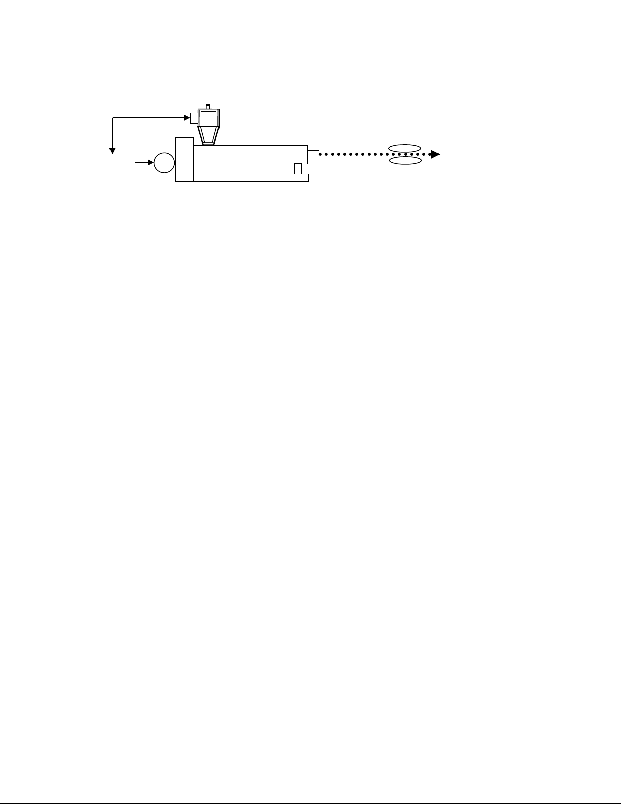
The LineMasterTM product range has the option of monitoring material consumption by a loss-in-
weight hopper mounted on the process throat. The weight consumption data can be reported to
one of two control options: Enhanced Extrusion Control with a Maguire blender integrates the
extrusion control functions into the blender controller for a single point of control. The second
option is Enhanced LIW Extrusion Control, which utilizes LineMaster Control Operator Interface
(XCC) to be used as a stand-alone solution for throughput or yield control. Additionally, it can be
utilized in a multi-layer control application.
The weight consumption data is communicated directly to the respective controller and updates
consumption information frequently. The loss-in-weight hopper determines accurate throughput
within 5 seconds and updates thereafter every 1 second.
XC CONTROL OPTIONS
LineMaster is a comprehensive range of products that is designed to serve the vast majority of
extrusion operations that require solutions based at every level of the cost / performance
spectrum. The available control options provide throughput control for pounds or kilograms per
hour, weight per length control for lb/ft or gm/M and gauge control in microns.
XC-1 Throughput Control
Control is maintained by monitoring the throughput of the process and regulating the extruder
speed. The XCC controller utilizing the consumption data from the LIW hopper communicates with
the XCD-X Extruder Drive Speed Control to adjust the extruder speed via a 0-10 volt signal to
maintain the throughput target.
XC-2 Yield Control
XC-2 offers the ability to maintain a product’s weight per length (lb/ft or gm/M) by monitoring the
process throughput against the line speed. An XCE Digital Encoder mounted on a take-off device
monitors the line speed. Control is accomplished by adjusting either the extruder speed with a
XCD-X Drive Speed Control Module by referencing the manually controlled line speed or
controlling the take-off speed with a XCD-T Line Speed Control Module from a manually controlled
extruder.
XC-3 Multi-Layer Yield Control via Computer and G2 Software
XC-3 provides complete weight per length control (lb/ft or gm/M), via simultaneous control of the
extruder and take-off. Controllers are connected via a high speed serial or Ethernet network using
the XC Software. Gauge or thickness control can be initiated in set-up utilizing data of the
materials or blend specific gravity.
Advanced Weigh Control Benefits:
Lines requiring constant feedback
Frequent job / material / production changes
Blenders not mounted on the extruder throat
Co-extrusion lines
Lines requiring frequent ramp up / ramp down control
Lines using only one material

Maguire Products, Inc.
7
LineMaster
Computer Control and Data Options
With the LineMasterTM product range, the Gravimetric Gateway TM (G2) software program is
available for centralized control and data reporting. The software program is an integral part of the
XC-3 Extrusion Multi-layer Control and as an option for mono- layer applications of throughput or
yield control.
A brief overview of G2
A Gravimetric GatewayTM Server (G2 Server) provides communication with all Maguire controllers
for data collection and control. The G2 software enables communication directly from the server
with one or more blender or loss-in-weight controllers to connect remotely from anywhere over a
TCP/IP network using the Gravimetric GatewayTM Client software. The server provides two-way
communication with the network of blenders and loss-in-weight controllers for constant retrieval of
information such as:
Precise weight of all materials
Settings (sending and retrieval)
Recipe numbers
Work order numbers
Operators information
The G2 server organizes and tracks material usage and allows the user to gather accurate
information according to a number of factors including: time period (day, shift, etc), process
machine, work order, operator, recipe, blender and line recipe.
Throughout and Yield Control
LineMaster can monitor and control up to 7 layers; each layer is graphically depicted. All lines
visually merge where the Total Throughput is displayed. Take-off and downstream controls are
displayed at the right showing line speed, weight per length and/or gauge.
A more detailed examination of each blender’s settings and output can be accessed through the
Line Blender Screen by clicking on the individual extruder.
Throughput Reporting
The software also allows reporting on average throughput, total throughput, and the percentage of
total uptime of an individual blender or all blenders in the line. Reports are based on start/stop
date and time, weight units and percentage of run time.
Event Monitoring
The computer software also incorporates an event monitoring service allowing users to access a
history of alarms, actions and changes.
Materials and Blend Management
The software can also store a complete dataset of materials and recipes used in production. This
data is easy to edit and maintain, and allows for full tracking of material consumption and
inventory management – a valuable tool for data regarding quality, certification, costs and
productivity.

Maguire Products, Inc.
8
LineMaster
REDUCE RESIN CONSUMPTION WITH
ENHANCED GRAVIMETRIC EXTRUSION YIELD CONTROL
The diagram on the following page illustrates a 3-layer film line utilizing LineMasterTM Extrusion
Control. Loss-in-weight hoppers are mounted on 3 extruders that are feeding the die producing the
film bubble. The loss-in-weight hoppers provide precise throughput data and an encoder (mounted
on nip rolls or any rotating shaft) provides line speed data. Any change in throughput due to
screen pack, back pressure, melt temperature or other variables is detected and adjusted for.
Typical process variations are reduced with LineMaster gravimetric control to within ± 0.5%,
significantly reducing resin consumption. Typically, 3 to 4% resin savings is realized resulting in
payback in as little as 6 months. LineMaster simplifies line start-up, enables rapid job changes and
reduces scrap during string-up.
LineMasterTM Encoder – Model XCE
Extruder Drive Speed Control – Model XCD-X
Take-off / Line Speed Control – Model XCD-T
LineMasterTM Speed Control modules communicate directly with the XCC or blender controllers.
The controller receives process throughput updates from the loss-in-weight hopper and
commands the speed control modules to increase or decrease screw rpm.
The speed control modules provide a 0 – 10 Vdc analog signal to the extruder or take-off drive
being controlled. The XCD Speed Control Modules include a digital potentiometer, which replaces
the existing manual pot or can communicate with an existing digital speed control. A toggle switch
is included to provide selection of either Manual or Automatic control.
APPLICATIONS
Wood Composite
Corrugated
Pipe & Tubing
Wire & Cable

Maguire Products, Inc.
9
LineMaster

Maguire Products, Inc.
10
LineMaster
Overview - XC-1 LineMaster® Throughput Control (lb/hr or kg/hr)
Monitors throughput - Adjusts extruder drive speed to maintain product weight per hour
Component Installation
The system is comprised of a mass flow hopper assembly, a controller with operator interface and
a drive speed control package.
The mass flow hopper assembly is mounted on the throat of the extruder. A weigh hopper
suspended from a set of load cells provides the material flow data to the LIW controller. The
extruder drive control package, which includes a digital potentiometer to replace the existing
analog extruder speed pot, is mounted in the control cabinet and monitors and controls the signal
to the extruder drive.
Principal of Operation
The XC-1 Extrusion Throughput Control System is designed to maintain a products weight over
time by monitoring the material consumption of the process through the mass flow hopper on the
throat of the extruder in pounds or kilos per hour, and adjusts the extruder speed to maintain the
desired throughput. The actual throughput is compared to a desired target throughput of the
product entered on the LIW controller. The LIW controller communicates to the XCD-X Extruder
Drive Control, which adjusts the voltage or reference signal to the extruder drive, which will
increase, or decrease to maintain the desired throughput.
A digital potentiometer replaces the existing rotary drive speed control on the extruder drive panel
and communicates with the XCD-X Extruder Drive Control which is mounted in or on the control
cabinet and is connected to the LIW controller.
aspc0910
LIW w/ XCC
M
EXTRUDER
Product
XCD
-
X
Dri
ve Speed Control

Maguire Products, Inc.
11
LineMaster
Typical Start-up
Upon a first time start-up of the process, the throughput control system is placed in the Manual
Mode. The LIW controller learns the rate of the material flow through the mass flow hopper within
45 seconds and enters the logarithmic value in the control parameters. The controller will display
the learned throughput rate and indicate the process can be switched into the Auto or Locked
Mode. A target value for the process throughput desired is entered as a set point on the LIW
controller. The system can be switched into the Auto or Lock Mode and the speed of the extruder
will be adjusted to maintain the target process throughput. If a change to the process throughput is
required the new target is entered and the controller will instruct the extruder drive to increase
crease or decrease respectively. The reaction of the LIW system to the process rate change is
almost instantaneous and will settle at the desired throughput within 45 seconds of the process
reaching the requested target.
Once the LIW controller learns the throughput rate of a material, it is stored in the memory of the
controller. The controller can be left in the Auto or Locked mode if the same material is continued
or a similar bulk density material is used. If a new material with a different bulk density is used, the
start-up procedure must be re-initiated.
Components
LIW-XX Mass Flow Hopper (sized for the required throughput)
as7190 Surge Hopper (optional)
XCC LineMaster Control Operator Interface
XC-1 LineMaster Extrusion Yield Control w/ Line Speed Control Package
includes the following components:
XCD-X Extruder Drive Control, Analog 1-10 Vdc
aspc0910 LIW to Drive Interface Cable, 100 ft.
An optional surge hopper, as7190, which mounts atop the LIW is available if the volume of
material in the transition from the mezzanine mounted blender is less than the capacity of the LIW
hopper
LIW MODEL THROUGHPUT
LB/HR
KG/HR
HOPPER CAPACITY
LIW-05 5 – 300 2.2 – 136 .3 ft3 8.5 liters
LIW-10 100 - 600 45 – 272 .6 ft3 17.0 liters
LIW-25 500 – 1,500 228 – 682 1.6 ft3 45.3 liters
LIW-40 1,000 – 3,000 454 – 1,364 2.5 ft3 70.8 liters

Maguire Products, Inc.
12
LineMaster
Overview - XC-2X LineMaster® Extrusion Yield Control w/ Extruder Drive Control
Monitors process throughput and take-off speed, controls extruder drive speed to maintain product
yield (weight per length)
Drive Speed Control
Component Installation
The system is comprised of a mass flow hopper assembly, a controller with operator interface, a
drive speed control package and an encoder.
The mass flow hopper is mounted on the throat of the extruder. A weigh hopper suspended from a
set of load cells provides the material flow data to the LIW controller. The drive speed control
package, which includes a digital potentiometer to replace the existing analog extruder speed pot,
is mounted in the control cabinet and monitors and controls the signal to the extruder drive. The
encoder or pulse generator is mounted on the haul off to monitor the speed of the line.
Principal of Operation
The XC-2X Extrusion Yield Control System is designed to maintain a products weight per length
(yield) by monitoring the material consumption of the process through the mass flow hopper on the
throat of the extruder in kilos per hour, and collates the data with the line speed monitored by an
encoder mounted on the shaft of the haul off in meters per minute to provide a calculated actual
product yield in grams or kilograms per meter. The actual yield is compared to a desired target
yield of the product entered on the LIW controller. The LIW controller communicates to the XCD-X
Extruder Drive Speed Control, which adjusts the voltage or reference signal to the extruder drive,
which will increase or decrease with respect to the line speed to maintain the desired yield.
A digital potentiometer replaces the existing rotary drive speed control on the extruder drive panel
and communicates with the XCD-X Drive Speed Control which is mounted in or on the control
cabinet and is connected to the LIW controller.
aspc0910
LIW w/ XCC
Encoder
XCE
-
01
M
EXTRUDER
Product
XCD
-
X
aspc2210

Maguire Products, Inc.
13
LineMaster
Typical Start-up
Upon a first time start-up of the process, the yield control system is placed in the Manual Mode.
The LIW controller learns the rate of the material flow through the mass flow hopper within 45
seconds and enters the logarithmic value in the control parameters. The controller will display the
learned yield rate and indicate the process can be switched into the Auto or Locked Mode. A
target value for the product weight per length desired is entered as a set point on the LIW
controller. The system can be switched into the Auto or Lock Mode and the speed of the extruder
will be adjusted to maintain the target weight per length value. As the line speed is increased to a
production level, the LIW controller will acknowledge the change and increase the signal to the
drive to maintain the desired product yield. The reaction of the LIW system to the process rate
change is almost instantaneous and will settle at the desired yield within 45 seconds of the
process reaching the final speed.
Once the LIW controller learns the throughput rate of a material, it is stored in the memory of the
controller. The controller can be left in the Auto or Locked mode if the same material is continued
or a similar bulk density material is used. If a new material with a different bulk density is used, the
start-up procedure must be re-initiated.
Components
LIW-XX Mass Flow Hopper (sized for the required throughput)
as7190 Surge Hopper (optional)
XCC LineMaster Control Operator Interface
XC-2X LineMaster Extrusion Yield Control w/ Extruder Drive Control Package
includes the following components:
XCD-X Extruder Drive Speed Control, Analog 1-10 Vdc
aspc0910 LIW to Drive Interface Cable, 100 ft.
XCE-01 Encoder, Pulse Generator
aspc2210 Encoder Interface Cable, 100 ft.
An optional surge hopper, as7190, which mounts atop the LIW is available if the volume of
material in the transition from the mezzanine mounted blender is less than the capacity of the LIW
hopper.
LIW MODEL THROUGHPUT
LB/HR
KG/HR
HOPPER CAPACITY
LIW-05 5 – 300 2.2 – 136 .3 ft3 8.5 liters
LIW-10 100 - 600 45 – 272 .6 ft3 17.0 liters
LIW-25 500 – 1,500 228 – 682 1.6 ft3 45.3 liters
LIW-40 1,000 – 3,000 454 – 1,364 2.5 ft3 70.8 liters

Maguire Products, Inc.
14
LineMaster
Overview - XC-2T LineMaster® Extrusion Yield Control - Take-off Drive Control
Provides control of haul-off to maintain weight per length via feedback from encoder mounted on
downstream haul-off
Component Installation
The system is comprised of a mass flow hopper assembly, a controller with operator interface, a
line speed control package and an encoder.
The mass flow hopper is mounted on the throat of the extruder. A weigh hopper suspended from a
set of load cells provides the material flow data to the LIW controller. The line speed control
package, which includes a digital potentiometer to replace the existing analog take-off speed pot,
is mounted in the control cabinet and monitors and controls the signal to the take-off drive. The
encoder or pulse generator is mounted on the haul off to monitor the speed of the line.
Principal of Operation
The XC-2T Extrusion Yield Control System is designed to maintain a products weight per length
(yield) by monitoring the material consumption of the process through the mass flow hopper on the
throat of the extruder in kilos per hour, and collates the data with the line speed monitored by an
encoder mounted on the shaft of the haul off in meters per minute to provide a calculated actual
product yield in grams or kilograms per meter. The actual yield is compared to a desired target
yield of the product entered on the LIW controller. The LIW controller communicates to the XCD-T
Take-off Drive Speed Control, which adjusts the voltage or reference signal to the Take-off drive,
which will increase or decrease with respect to the extruder speed to maintain the desired yield.
A digital potentiometer replaces the existing rotary drive speed control on the take-off drive panel
and communicates with the XCD-T Take-off Speed Control which is mounted in or on the control
cabinet and is connected to the LIW controller.
Typical Start-up
Upon a first time start-up of the process, the yield control system is placed in the Manual Mode.
The LIW controller learns the rate of the material flow through the mass flow hopper within 45
seconds and enters the logarithmic value in the control parameters. The controller will display the
learned yield rate and indicate the process can be switched into the Auto or Locked Mode. A
target value for the product weight per length desired is entered as a set point on the LIW
controller. The system can be switched into the Auto or Lock Mode and the speed of the extruder
will be adjusted to maintain the target weight per length value. As the line speed is increased to a
production level, the LIW controller will acknowledge the change and increase the signal to the
LIW w/ XCC
Encoder
XCE
-
01
EXTRUDER
Product
M
M
XCD
-
T
aspc0910
aspc2210
Line Speed Control

Maguire Products, Inc.
15
LineMaster
drive to maintain the desired product yield. The reaction of the LIW system to the process rate
change is almost instantaneous and will settle at the desired yield within 45 seconds of the
process reaching the final speed.
Once the LIW controller learns the throughput rate of a material, it is stored in the memory of the
controller. The controller can be left in the Auto or Locked mode if the same material is continued
or a similar bulk density material is used. If a new material with a different bulk density is used, the
start-up procedure must be re-initiated.
Components
LIW-XX Mass Flow Hopper (sized for the required throughput)
as7190 Surge Hopper (optional)
XCC LineMaster Control Operator Interface
XC-2T LineMaster Extrusion Yield Control w/ Line Speed Control Package
includes the following components:
XCD-T Take-off Drive Speed Control, Analog 1-10 Vdc
aspc0910 LIW to Drive Interface Cable, 100 ft.
XCE-01 Encoder, Pulse Generator
aspc2210 Encoder Interface Cable, 100 ft.
An optional surge hopper, as7190, which mounts atop the LIW is available if the volume of
material in the transition from the mezzanine mounted blender is less than the capacity of the LIW
hopper
LIW MODEL THROUGHPUT
LB/HR
KG/HR
HOPPER CAPACITY
LIW-05 5 – 300 2.2 – 136 .3 ft3 8.5 liters
LIW-10 100 - 600 45 – 272 .6 ft3 17.0 liters
LIW-25 500 – 1,500 228 – 682 1.6 ft3 45.3 liters
LIW-40 1,000 – 3,000 454 – 1,364 2.5 ft3 70.8 liters

Maguire Products, Inc.
16
LineMaster
XC-3 LineMaster® Yield Control – Extruder & Take-off Drive Control
Monitors throughput and line speed. Adjusts extruder and line speed to maintain product weight
per length. Requires XC-C LineMaster computer controller and is typically used for multi-layer co-
ex applications.
Component Installation
The system is comprised of a mass flow hopper assembly, a controller with operator interface, an
extruder drive speed control package, a line speed control package and an encoder. The
LineMaster XC-LMC computer control is required for simultaneous control of both extruder drive
speed and line speed.
The mass flow hopper is mounted on the throat of the extruder. A weigh hopper suspended from a
set of load cells provides the material flow data to the LIW controller. The line speed control
package, which includes a digital potentiometer to replace the existing analog take-off speed pot,
is mounted in the control cabinet and monitors and controls the signal to the take-off drive. The
encoder or pulse generator is mounted on the haul off to monitor the speed of the line. The
extruder drive speed control package, which includes a digital potentiometer to replace the
existing analog extruder speed pot, is mounted in the control cabinet and monitors and controls
the signal to the extruder drive. The two drive controllers communicate to with one another to
provide a synchronous ramp of all drives as directed by the LineMaster XC-LMC computer.
Principal of Operation
The XC-3 Extrusion Yield Control System is designed to maintain a products weight per length
(yield) by monitoring the material consumption of the process through the mass flow hopper on the
throat of the extruder in kilos per hour, and collates the data with the line speed monitored by an
encoder mounted on the shaft of the haul off in meters per minute to provide a calculated actual
product yield in grams or kilograms per meter. The actual yield is compared to a desired target
yield of the product entered on the LIW controller. The LIW controller communicates to the XCD-X
Extruder Drive Speed Control which adjusts the voltage or reference signal to the extruder drive to
increase or decrease with respect to the line speed to maintain the desired yield.
Digital potentiometers replaces the existing rotary drive speed control on the take-off drive and
extruder drive and communicate with the XCD-T Take-off Speed Control and XCD-X Extruder
Drive Speed Control which is mounted in or on the control cabinet and is connected to the LIW
controller.
Typical Start-up
Encoder
XCE
-
01
EXTRUDER
Product
M
M
LIW
XCD
-
T
XCD
-
X
aspc0910 aspc2210
aspc2510
Computer
XC-LMC
Line Speed Control
Drive Speed Control

Maguire Products, Inc.
17
LineMaster
Upon a first time start-up of the process, the yield control system is placed in the Manual Mode.
The LIW controller learns the rate of the material flow through the mass flow hopper within 45
seconds and enters the logarithmic value in the control parameters. The controller will display the
learned yield rate and indicate the process can be switched into the Auto or Locked Mode. A
target value for the product weight per length desired is entered as a set point on the LIW
controller. The system can be switched into the Auto or Lock Mode and the speed of the extruder
will be adjusted to maintain the target weight per length value. As the line speed is increased to a
production level, the LIW controller will acknowledge the change and increase the signal to the
drive to maintain the desired product yield. The reaction of the LIW system to the process rate
change is almost instantaneous and will settle at the desired yield within 45 seconds of the
process reaching the final speed.
Once the LIW controller learns the throughput rate of a material, it is stored in the memory of the
controller. The controller can be left in the Auto or Locked mode if the same material is continued
or a similar bulk density material is used. If a new material with a different bulk density is used, the
start-up procedure must be re-initiated. According to the configuration of the XC program the
drives will simultaneously increase or decrease as either the line speed, throughput or gauge
requirements are changed.
Components
LIW-XX Mass Flow Hopper (sized for the required throughput)
as7190 Surge Hopper (optional)
XCC LineMaster Control Operator Interface
XC-3 LineMaster Extrusion Yield Control w/ Drive & Line Speed Control
includes the following components:
XCD-X Extruder Drive Speed Control, Analog 0 – 10 Vdc
aspc0910 LIW to Drive Interface Cable, 100 ft.
XCD-T Take-off Drive Speed Control, Analog 0 -10 Vdc
aspc2510 Drive Communications Cable, 100 ft.
XCE-01 Encoder, Pulse Generator
aspc2210 Encoder Interface Cable, 100 ft.
An optional surge hopper, as7190, which mounts atop the LIW is available if the volume of
material in the transition from the mezzanine mounted blender is less than the capacity of the LIW
hopper
LIW MODEL THROUGHPUT
LB/HR
KG/
H
R
HOPPER CAPACITY
LIW-05 5 – 300 2.2 – 136 .3 ft3 8.5 liters
LIW-10 100 - 600 45 – 272 .6 ft3 17.0 liters
LIW-25 500 – 1,500 228 – 682 1.6 ft3 45.3 liters
LIW-40 1,000 – 3,000 454 – 1,364 2.5 ft3 70.8 liters

Maguire Products, Inc.
18
LineMaster
LineMasterTM Kits and Components
Parts Identification
Extruder Speed Control
Take-off Speed Control LineMaster Controller
Encoder, Encoder Wheel
100 foot cable 24 volt power supply
Maguire LIW 5
Maguire LIW 10
Maguire LIW 20
Maguire LIW 40
Optional Components:
Throat Mount Adapter
with drain port
Surge Hopper
1.25 ft3 - LIW-05 & 10
2.25 ft3 - LIW-25 & 40

Maguire Products, Inc.
19
LineMaster
LineMasterTM Kits
Depending on the application your kit may include the following:
o Extrusion Control – LineMaster Controller, Extruder Speed Control Interface, Cabling
and strain relief.
o Yield-X - LineMaster Controller, Extruder Speed Control Interface, Cabling, cable strain
relief, mounting hardware, 24 Volt Power Supply, Encoder, Encoder Wheel (12 inch
circumference), Encoder Cable.
o Yield T - LineMaster Controller, Take-off Speed Control Interface, Cabling, cable strain
relief, mounting hardware, 24 Volt Power Supply, Encoder, Encoder Wheel (12 inch
circumference), Encoder Cable.
o Yield D - LineMaster Controller, Extruder Speed Control Interface, Take-off Speed
Control Interface, Cabling, cable strain relief (2), mounting hardware, 24 Volt Power
Supply, Encoder, Encoder Wheel (12 inch circumference), Encoder Cable. Requires
the G2 software and dedicated computer system. G2 Not included with kit but may be
provided separately.
Additional Options
o LineMaster 12 Software Controller – Up to 12 components, controlling a blender and a
LIW hopper (Loss-In-Weight hopper).
o LIW Stand Alone LineMaster Controller – Controls a single LIW hopper (Loss-In-Weight
hopper) tracking throughput of the LIW.

Maguire Products, Inc.
20
LineMaster
LineMaster
Installation
In this section:
Safety Warnings
Loss-In-Weigh Hopper Installation
General Wiring Installations Notes and Considerations
XC-1 – Extrusion Control Installation
XC-2 - Yield Control X or Yield Control T Installation
XC-3 – Yield D Installation
Safety Warnings
Electrical Connection
RISK OF INJURY!
Only qualified technicians should make electrical
connections. These instructions provide wiring diagrams.
Wiring installations should only be performed by a qualified
electrician who is familiar with these types of installation.
Prior to installation, thoroughly review the wiring diagram
specific to your installation.
Wire Installations – Preventing Interference or Damage
When installing communication wires, be sure to avoid any sources of
interference such as vacuum loader lines (discharged static), high voltage
lines and transformers and florescent lights. You should avoid these
sources by a distance of a foot or more so that communication is not
disrupted by interference and sensitive electronic components are not
damaged.
Lifting
DANGER OF INJURY!
If the weight is unevenly distributed, the LIW Hopper may tip and injure
people when it is lifted.
Weights of the LIW Hopper Models range from 56 pounds (25.5 Kg) to 140
pounds (63.6 Kg). Lift points are the vertical supports of the black metal
frame.
Table of contents
Other MAGUIRE Controllers manuals
Popular Controllers manuals by other brands

ARAG
ARAG Bravo 3 Series ADDITION TO INSTRUCTION BOOKLET

Mitsubishi Electric
Mitsubishi Electric Melservo-J5 MR-J5 Series user manual

Tech Controllers
Tech Controllers EU-T-4.1 user manual

Victor
Victor EDGE ESS3 PARTS, SERVICE & REPAIR BULLETIN

Aruba
Aruba 7030 installation guide

Xante
Xante Accel-a-Graphix CT4 user guide