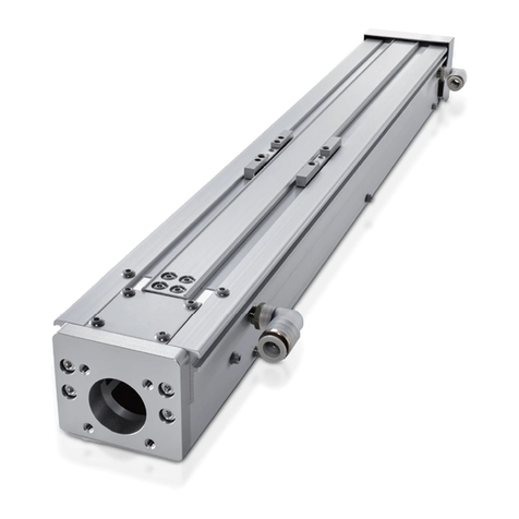
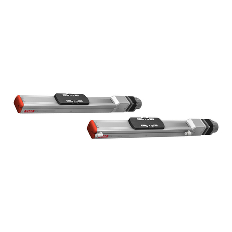
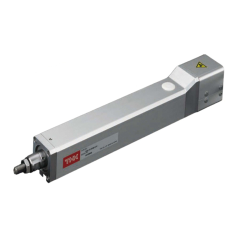
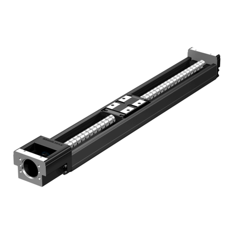
THK KRF User manual

INSTRUCTION MANUAL
THK Electrical Actuator Compact Series
KRF
No.2040-2 (0) E

Table of Contents
iKRF
1. Introduction 1-1
1-1 Acknowledgment 1-1
1-2 About this manual 1-1
1-3 How to use this product 1-2
1-4 About product support 1-2
1-5 About related instruction manuals 1-2
1-6 Product and company information 1-2
2. Safety Precautions 2-1
2-1 Warning indications on safety 2-1
2-2 Safety precautions 2-1
2-3 Checking the precautions/instruction labels 2-3
3. Nameplates Display 3-1
3-1 Nameplates display and serial number 3-1
4. Specifications 4-1
4-1 Basic specification 4-1
4-2 Speed and load capacity characteristic diagram 4-2
5. Structure and Model Numbers 5-1
5-1 Structure and part names 5-1
5-2 Model configuration 5-2
6. Storage and Transportation 6-1
6-1 Precautions to be observed for safe use 6-1
6-2 Precautions to be observed for prevention of product fault or fracture 6-2
7. Installation and Operation 7-1
7-1 Precautions to be observed for safe use 7-1
7-2 Precautions to be observed for prevention of product fault or fracture 7-2
7-3 Other precautions 7-3
7-4 Motor mounting method 7-4
7-5 Base mounting method 7-15
7-6 Mounting method for objects to be mounted 7-17
7-7 Positioning pin length 7-18

Table of Contents
ii KRF
8.Maintenance 8-1
8-1 Precautions to be observed for safe use 8-1
8-2 Precautions to be observed for prevention of product fault or fracture 8-1
8-3 Daily inspection 8-2
8-4 Periodical inspection 8-2
8-5 Lubrication 8-2
8-6 Method for supplying grease 8-3
8-7 How to replace the strip seal 8-21
8-8 Belt replacement method for motor return type 8-33
8-9 Free warranty period 8-37
8-10 Usage conditions (range) 8-37
8-11 Warranty scope 8-37
8-12 Exclusion of warranty liability 8-38
8-13 Delivery conditions 8-38
9.Appendix 9-1
9-1 Table weight 9-1
9-2 Permissible input torque 9-1
9-3 Static permissible moment 9-1
9-4 Static permissible load 9-2
9-5 Permissible rotational speed 9-2
9-6 Introduction of the grease 9-3
9-7 Introduction of the grease gun unit 9-4

1-1 KRF
1. Introduction
1.
Introduction
1-1 Acknowledgment
Thank you for purchasing the Compact Series KRF.
This product is a medium speed, medium load capacity and long service life actuator.
This product is designed and manufactured to be incorporated in devices with wide range of
application including conveyance system, implementing equipment, automated assemblers, and
positioning equipment, etc.
We hope our creative inventions and unique technologies contribute to your further prosperity.
1-2 About this manual
1-2-1 Intended audience
The person in charge of designing embedded systems of the product and installing, wiring, and
maintaining the product, and the person who actually uses the product.
1-2-2 Using This Manual
This manual describes correct handling methods and precautions for the product.
For the maximum performance and long life of the product, carefully read and understand this
manual to safely and correctly use the product.
If you use the printed version of this manual, be sure to keep it in the place that the audience can
refer to it when needed.
1-2-3 Notice and attention
Do not use or handle the product in the ways that are not described in this manual.
Do not reproduce, reprint, or lend the whole contents or a part of this manual without permission.
Please note that the description in this manual is subject to change without prior notice in the
future, due to improvements of the product or other reasons.
We have made all possible efforts to make the content of this manual accurate. However, if you
nd any mistake or uncertainty in this manual, please contact THK.
Drawings throughout this manual are only intended as typical examples, and may differ from your
product.
Note that THK shall not be liable for any result incurred by applying this manual, regardless of the
reason.
This manual is also applied to special types of product. However, the descriptions provided in the
delivery specication drawings or delivery specication documents of those special types take
precedence over this manual. * Special types represent the products that have different materials
and specications from those of the standard products on catalogs.
1-2-4 Notation of this manual
Notes that can lead to unsatisfactory functions, errors, or damages of the product if not observed while using the product.
Supplementary information for the description.
Reference information for the description.
Important
Supplement
Reference

1-2 KRF
1. Introduction
1-3 How to use this product
This product must not be used for the devices or systems that are used under the situations that
may be fatal to human life.
If you consider using this product for special applications such as passenger movement vehicle,
medical, aerospace, nuclear power, and electric power devices or systems, be sure to consult
with THK in advance.
This product is manufactured under the strict quality control, however, that does not mean
that the product is free from failure. For applications to the equipment that may suffer serious
accidents or loss from the failure of this product, install safety devices or backup devices that
prevent such serious accidents or loss.
If you purchase this product with a motor, the applicable driver controller is TSC, TLC, or THC. Please
note that driver controllers other than the above cannot be used.
1-4 About product support
We have made all possible efforts to make the content of this manual accurate. However, if you nd
any mistake or uncertainty in this manual, please contact THK.
For the following information, please contact THK.
Technical support for this product
1-5 About related instruction manuals
When you use the actuator KRF, read the following instruction manuals as necessary.
· Controller series Driver controller TSC
· Controller series Driver controller TLC
· Controller series Driver controller THC
· Controller series Network unit TNU
· Controller series Setup tool D-STEP
· Controller series Digital operator TDO
1-6 Product and company information
To nd the latest product and company information, we recommend you to periodically access our
website.
Website URL: https://www.thk.com/
Technical support website URL: http://www.tech.thk.com/
Important

2-1 KRF
2.
Safety Precautions
2-2 Safety precautions
This section describes important precautions that you must observe.
General
While this product is operating or operable, do not enter the working area of any
moving part.
Otherwise, it may cause you to touch the moving part and injure you.
While the motor or sensor is energized, do not move or install this product.
Otherwise, it may cause electric shocks, or cause malfunction that could lead to injury.
Installation and operation
If any moving part may fall by its own weight in vertical application or the like, provide
a safeguard for preventing the part from falling.
If any moving part falls, it may cause injury or damage.
While this product is operating, do not touch any moving part or rotating part.
Otherwise, it may cause your hand to be caught and injured.
Maintenance
Turn off the machine (turning power off) before conducting any maintenance.
Otherwise, it may cause electric shocks, or cause malfunction that could lead to injury.
If two or more people are involved in the operation, confirm the procedures such
as sequences, signs, and abnormalities in advance, and appoint another person for
monitoring the operation.
Failure to do so may cause an unexpected accident.
Warning
2-1 Warning indications on safety
This manual uses the following warning indications according to safety matters. The descriptions
next to warning indications on safety are important messages. Be sure to observe those
descriptions.
Warning
"Erroneous handling may cause death or serious injury
to a person"
Caution
"Erroneous handling may cause injury to a person or
property damage only"
"Prohibitions (don't)"
"Obligations (do)"
2.
Safety Precautions

2-2 KRF
2.
Safety Precautions
General
Do not stand on this product or the packaging box.
Otherwise, it may cause fault or damage, or cause falling that could lead to injure.
Do not impact this product.
Otherwise, it may cause fault or damage, or injure you.
Do not apply a load that exceeds the permissible level.
Otherwise, it may cause fault or damage, or may cause abnormal operation that could lead to
injury.
* For your reference, see the Appendix, which contains the static permissible moment and
permissible input torque for each model number.
Do not disassemble or alter this product.
Otherwise, it may cause foreign material to enter the product, which could result in fault or
adversely affect the performance or service life. Or may cause abnormal operation that could
lead to injury.
Unpacking
Be careful not to hit your hands or body against protruded parts.
Otherwise, it may cause injury,or cause fault or fracture.
Check whether the delivered product is the product you ordered.
Using a wrong product may cause malfunction that could lead to injury or fault.
Check whether the product has any fractured parts.
Using a fractured product may cause injury or fault.
* If you nd any defect, contact our Sales Division.
Transportation
Do not drop or hit this product.
Otherwise, it may cause injury or fracture, or a functional loss.
When transporting this product, do not hold any moving part or the cover.
Also, do not hold the side cover from the both sides.
Otherwise, it may cause the product to fall, leading to injury, or cause fault or fracture.
When transporting this product, do not hold the motor, the sensor or the cable.
Otherwise, it may cause the product to fall, leading to injury, or cause fault or fracture.
When carrying this product, hold the bottom face of the product.
Otherwise, it may cause the product to fall, leading to injury, or cause fault or fracture.
* See the appendix for the weight of the product.
Installation and operation
Firmly secure this product before operating it.
Failure to do so may cause abnormal operation that could cause injury, fault or fracture.
If anomaly occurs, immediately stop the machine.
Failure to do so may cause abnormal operation that could cause injury, fault or fracture.
Do not exceed the maximum speed when using the product.
Otherwise, it may cause fault or damage,or may cause abnormal operation that could lead to
injury. For your reference, see the specication (→P.4-1), which contains the maximum speed
for each model number at each stroke.
Do not use the failed and broken product.
Otherwise, it may cause injury or machine failure.
Caution
2.
Safety precautions

2-3 KRF
2.
Safety Precautions
2.
Safety precautions
2-3 Checking the precautions/instruction labels
This product is afxed with precautions/instruction labels. Identify them when unpacking the
product.
Fig.1 shows the afxing position.
Caution – Getting caught
取扱説明書をお読みください。
Review the manual.
取扱説明書をお読みください。
Review the manual.
Fig. 1 KRF Precautions/instruction labels affixing positions

3-1 KRF
3.
Nameplates Display
3-1 Nameplates display and serial number
Fig. 2 shows the nameplate format of the Compact Series KRF.
TYPE No. : Actuator model
SERIAL No.: Serial number
3.
Nameplates Display
Fig. 2 KRF Nameplate details

4-1 KRF
4. Specifications
4-1 Basic specification
4.
Specifications
The basic specication of KRF is shown as follows. Do not exceed the following basic specication
when using the product. Otherwise, it may cause fault or damage, or may cause abnormal
operation that could lead to injury.
When using servo driver controller TLC/THC
Model
number
Ball screw
lead
[mm]
Stroke
[mm]
Motor
rated
output
[W]
Maximum load capacity*2 [kg]
Maximum speed at each stroke*3 [mm/s]
Horizontal
mount
Wall
mount
Vertical
mount
Stroke
to 300 350 400 450 500 550 600 650 700 750 800
KRF4 6 50 to 300 50 6 5.5 4 300
KRF5
6 50 to 550
50
19 14 6 300 250
10 50 to 550 15 12.5 3.5 500 430
KRF6
6 50 to 800
100
35 24 10 300 260 220 200 170 150
10 50 to 800 30 22 5 500 440 380 330 290 260
*1 This assumes a speed at the rated motor revolution (3,000min-1).
*2 The maximum load capacity assumes the capacity at the rated speed under 0.5 G for horizontal and wall mounts,
and 0.3 G for vertical mount.
*3 The maximum speed is the value restricted by the motor rotational speed (at 3000 min-1) or by the permissible
rotational speed of the ball screw.
When using stepper driver controller TSC
Model
number
Ball screw
lead
[mm]
Stroke
[mm]
Maximum load capacity*1 [kg] Maximum speed at each stroke*1 [mm/s]
Horizontal
mount
Wall
mount
Vertical
mount
Stroke
to 300 350 400 450 500 550 600 650 700 750 800
KRF3 6 50 to 300 3 3 1.5 300
KRF4 6 50 to 300 6.5 6 4 300
KRF5
6 50 to 550 20 14.5 7.5 300 250
10 50 to 550 10 10 6 500 430
*1 The maximum load capacity and the maximum speed vary with usage conditions. For details, see "Basic
specication" and "Speed and Load Capacity Relationship Diagram" for each model number.

4-2 KRF
4. Specifications
4-2 Speed and load capacity characteristic diagram
Load capacity and maximum speed vary with usage conditions.
Use the product within the range of following characteristic diagram.
KRF3 (28P)∙∙∙∙Stepper driver controller TSC
Lead 6 mm
Horizontal/wall-mount
Speed [mm/s]
Load capacity [kg]
0
0.5
1
1.5
2
2.5
3
3.5
0 50 100 150 200 250 300 350
Vertical mount
Speed [mm/s]
Load capacity [kg]
0
0.5
1
1.5
2
0 50 100 150 200 250 300 350
4.
Specifications

4-3 KRF
4. Specifications
KRF4 (35P)∙∙∙∙Stepper driver controller TSC
Lead 6 mm
Horizontal mount
Speed [mm/s]
Load capacity [kg]
0
1
2
3
4
5
6
7
8
0 50 100 150 200 250 300 350
6.5
Wall mount
Speed [mm/s]
Load capacity [kg]
0
1
2
3
4
5
6
7
8
0 50 100 150 200 250 300 350
Vertical mount
Speed [mm/s]
Load capacity [kg]
0
0.5
1
1.5
2
2.5
3
3.5
4
4.5
0 50 100 150 200 250 300 350
4.
Specifications

4-4 KRF
4. Specifications
KRF5 (42P)∙∙∙∙Stepper driver controller TSC
Lead 6 mm
Horizontal mount
Speed [mm/s]
Load capacity [kg]
0
5
10
15
20
25
0 50 100 150 200 250 300 350 400 450 500 550
8
Wall mount
Speed [mm/s]
Load capacity [kg]
0
2
4
6
8
10
12
14
16
18
0 50 100 150 200 250 300 350 400 450 500 550
14.5
Vertical mount
Speed [mm/s]
Load capacity [kg]
0
1
2
3
4
5
6
7
8
9
0 50 100 150 200 250 300 350 400 450 500 550
1.5
4.
Specifications

4-5 KRF
4. Specifications
Lead 10 mm
Horizontal mount
Speed [mm/s]
Load capacity [kg]
0
5
10
15
20
25
0 50 100 150 200 250 300 350 400 450 500 550
Wall mount
Speed [mm/s]
Load capacity [kg]
0
2
4
6
8
10
12
14
16
18
0 50 100 150 200 250 300 350 400 450 500 550
5
Vertical mount
Speed [mm/s]
Load capacity [kg]
0
1
2
3
4
5
6
7
8
9
0 50 100 150 200 250 300 350 400 450 500 550
0.5
4.
Specifications

4-6 KRF
4. Specifications
4.
Specifications
KRF4 (50W)∙∙∙∙Servo driver controller TLC
Lead 6 mm
Horizontal mount
Speed [mm/s]
Load capacity [kg]
0
1
2
3
4
5
6
7
0 10050 200 250 350150 300 400
Wall mount
Speed [mm/s]
Load capacity [kg]
0
1
2
3
4
5
6
0 10050 200 250150 300 350 400
5.5
Vertical mount
Speed [mm/s]
Load capacity [kg]
0
1
2
3
4
5
0 100 150 250 35050 200 300 400

4-7 KRF
4. Specifications
4.
Specifications
KRF5 (50 W)∙∙∙∙Servo driver controller TLC
Lead 6 mm
Horizontal mount
0
5
10
15
20
25
0 50 100 150 200 250 300 350
Speed [mm/s]
Load capacity [kg]
19
14
Wall mount
0
5
10
15
20
25
0 50 100 150 200 250 300 350
Speed [mm/s]
Load capacity [kg]
Vertical mount
Speed [mm/s]
Load capacity [kg]
0
2
4
6
8
0 50 100 150 200 250 300 350

4-8 KRF
4. Specifications
4.
Specifications
Lead 10 mm
Horizontal mount
0
5
10
15
20
25
0 100 200 300 400 500 600
Speed [mm/s]
Load capacity [kg]
Wall mount
0
5
10
15
20
25
0 100 200 300 400 500 600
Speed [mm/s]
Load capacity [kg]
12.5
Vertical mount
0
1
2
3
4
0 100 200 300 400 500 600
Speed [mm/s]
Load capacity [kg]
3.5

4-9 KRF
4. Specifications
4.
Specifications
KRF6 (100 W)∙∙∙∙Servo driver controller THC
Lead 6 mm
Horizontal mount
Speed [mm/s]
Load capacity [kg]
Wall mount
Speed [mm/s]
Load capacity [kg]
Vertical mount
Speed [mm/s]
Load capacity [kg]
0
10
20
30
40
0 50 100 150 200 250 300 350
0
5
10
15
20
25
30
0 50 100 150 200 250 300 350
0
2
4
6
8
10
12
0 50 100 150 200 250 300 350
35

4-10 KRF
4. Specifications
4.
Specifications
Lead 10 mm
Horizontal mount
0
10
20
30
40
0 100 200 300 400 500 600
Speed [mm/s]
Load capacity [kg]
Wall mount
0
5
10
15
20
25
0 100 200 300 400 500 600
Speed [mm/s]
Load capacity [kg]
22
Vertical mount
0
1
2
3
4
5
6
0 100 200 300 400 500 600
Speed [mm/s]
Load capacity [kg]

5-1 KRF
5.
Structure and Model Numbers
5-1 Structure and part names
The name of each part of this product is shown in Fig. 3.
Housing-B cover
Housing A cover
Table cover
Table
Strip seal
Intermediate ange
Base
Motor
TLC, THC specications, without motor
Side cover
Housing-B cover
Table cover
Table
Strip seal
Cover return
Base
Motor
Side cover
Motor mounting plate
Return
Motor end cover
Table
TSC specications
Housing-B cover
Motor cover
Table cover
Strip seal
Base
Side cover
Fig. 3 Structure and part names of KRF (* KRF6 has no base. )
* For details such as the dimensions and accuracy, see the delivery specication drawings or the
catalog of Compact Series KRF.
If you have any question, contact THK.
5.
Structure and Model Numbers
This manual suits for next models
4
Table of contents
Other THK Controllers manuals
Popular Controllers manuals by other brands

ShowLed
ShowLed Chameleon manual
Ascon tecnologic
Ascon tecnologic Y39 operating instructions

Honeywell
Honeywell CVL4022ASVAV1 Engineering guide
Electronic Research Group
Electronic Research Group EC130 Technical manual
Bodine
Bodine 0790 Instructions for installation and operation
Samson
Samson BR 31a Series Operating, Assembly and Maintenance Instructions
Swegon
Swegon CONDUCTOR W4 Series Installation instruction
IBM
IBM 3745 Series installation instructions
Inter-m
Inter-m VRC-1104T operating manual
Eaton
Eaton ER9.3-10 manual

Barnett Engineering
Barnett Engineering ProTalk Plus B1290 operating manual
Emerson
Emerson EIM 2000 Series Installation and maintenance manual
