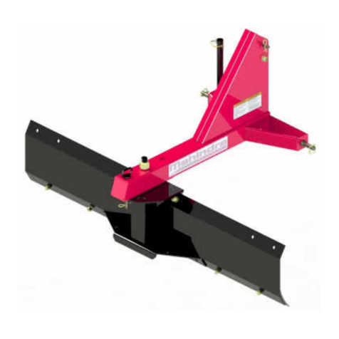
Mahindra MXSB-56 User manual

1
For
READ&FOLLOWALLSAFETYRULES&INSTRUCTIONSBEFORE
OPERATINGYOUREQUIPMENT
109301_EN R
-
20171019
*ASSEMBLY *REPAIRPARTS
*OPERATION *MAINTENANCE
*109301*
MXSB-56

2
LIMITED WARRANTY
Conditions and Products Covered:
BERCOMAC guarantees any part of the product or accessory
manufactured by BERCOMAC and found in the reasonable
judgment of BERCOMAC to be defective in material and or
workmanship will be repaired or replaced by an authorized
dealer without charge up to our maximum labor rates and pre-
established times. For replacement parts only standard ground
freight services are covered. This warranty applies to the
products bought and used in North America.
Warranty Period for Implement mounted on Max & eMax
tractors (from date of the original retail purchase)
Residential or light commercial (light agricultural) use: 2
years
Commercial (agricultural), heavy commercial, professional
or rental use: 90 days
Exceptions Noted Below; the following items have a different
coverage conditions and limited time:
Tire Chains:
o90 days, residential or light commercial use
oNo warranty for regular commercial, heavy
commercial, professionnal or rental use.
Engines: Will vary as per the manufacturer
Please refer to the engine manufacturer’s warranty
statement included with the unit. BERCOMAC is not
authorized to handle warranty adjustments on engines.
Items and Conditions NOT Covered:
This warranty does not cover the following:
Pick-up or delivery charges or in-home services fees.
Any damage or deterioration of the unit, parts and or finish
of these due to normal use, wear and tear, or exposure.
Cost of regular use or maintenance service or parts, such as
gas, oil, lubricants, tune-up parts, and adjustments.
Any part or accessory which has been altered, modified,
misused, neglected, accidentally damaged or not properly
installed, maintained, stored or repaired not in accordance
withtheinstructionsintheowner’smanual.
Repair due to normal wear and or any wear items such as
shear pins, bolts, belts, winch cable, cutting edge, skid
shoes, etc.
Expedited freight fee services for replacement parts.
Shear bolts and shear pins are to be considered as a
preventive measure not as an assured protection, any
damages resulting from the lack of shear bolts breakage are
not covered.
NOTE: All warranty work must be performed by an authorized
dealer using original (manufacturer) replacement parts.
Owner’sResponsibilities:
BERCOMAC’s defective equipment or part must be returned
to an authorized dealer within the warranty period for repairs.
In the event that defective merchandise must be returned to
manufacturer for repairs, freight fees are prepaid and a written
authorization from BERCOMAC must be obtained by dealer
prior to the shipment. This warranty extends only to
equipment operated under normal conditions. To validate a
warranty claim, it is the user’s responsibility to maintain and
servicetheunitasspecifiedintheowner’smanualortohave
the unit serviced at their dealer at their expense.
General Conditions:
The sole liability of BERCOMAC with respect to this warranty
shall be strictly and exclusively repair and replacement as
mentioned herein. BERCOMAC shall not have any liability for
any other costs, loss or damage, including but not limited to,
any incidental or consequential loss or damage.
Taking advantage of the warranty does not in any way extend
the length or renewal of the warranty.
In particular, without being limited to, BERCOMAC shall have
no liability or responsibility for:
Travel time, overtime, after hours time or other
extraordinary repair charges or relating to repairs and or
replacements outside of normal business hours.
Rental of like or similar replacement equipment during the
period of any, repair or replacement work.
Any communicating or travel charges.
Loss or damage to person or property other than that
covered by the terms of this warranty.
Any claims for lost revenue, lost profit or any similar costs
as a result of damage or repair.
Attorney’sfees.
BERCOMAC’s responsibility in respect to claims is limited to
making the required repairs or replacement without charge up
to our maximum labor rates and pre-established times and no
claim of breach of warranty shall be cause for cancellation or
rescission of the contract of sale of any product or accessory.
In no event shall recovery of any kind be greater than the
amount of the purchase price of the product sold.
This warranty gives you specific legal rights. You may also
have other rights, which vary from state to state
.
NOTE: Bercomac reserves the right to change or improve the design of any part or accessory without assuming any obligation to modify
any product previously manufactured.
Instructions for Obtaining Warranty Services: Contact the Mahindra dealer where equipment was purchased or any other Mahindra
service dealer to arrange service at their dealership. To locate a dealer convenient to you, access our website at
www.mahindrausa.com.
Don't forget to bring your proof of purchase (sales receipt) to the Mahindra dealer.
Revised 12-05-2011

3
TABLEOFCONTENTS
INTRODUCTION
......................................................................................................................................................
2
SAFETYPRECAUTIONS
........................................................................................................................................
3
SAFETYDECALS
....................................................................................................................................................
5
ASSEMBLY
Step1 SnowblowerPreparation
............................................................................................................
6
Step2: SnowblowerInstallation
................................................................................................................
7
OPERATION
SnowblowerOperation
...............................................................................................................................
9
Controls
.......................................................................................................................................................
9
SnowRemoval
...........................................................................................................................................
9
MAINTENANCE
Adjustments
................................................................................................................................................
10
Lubrication
...................................................................................................................................................
10
ShearBoltReplacement
............................................................................................................................
10
BeltReplacement
.......................................................................................................................................
11
PulleyReplacement
....................................................................................................................................
11
DISMOUNTING&STORAGE
.................................................................................................................................
12
TROUBLESHOOTING
.............................................................................................................................................
13
PARTSBREAKDOWNANDPARTSLIST
56’’Snowblower
.........................................................................................................................................
14
Chute
.........................................................................................................................................................
18
TORQUESPECIFICATIONTABLE
.......................................................................................................................
20
PAGE
iii

1
INTRODUCTION
TO THE PURCHASER
This new accessory was carefully designed to give years of dependable service. This manual has been provided to
assist in the safe operation and servicing of your attachment.
NOTE: All photographs and illustrations in the manual may not necessarily depict the actual models or attachment, but
are intended for reference only and are based on the latest product information available at the time of publication.
Familiarize yourself fully with the safety recommendations and operating procedures before putting the machine to
use. Carefully read, understand and follow these recommendations and insist that they be followed by those who will
use this attachment.
THIS SAFETY ALERT SYMBOL IDENTIFIES AN IMPORTANT SAFETY MESSAGE IN THIS
MANUAL THAT HELPS YOU AND OTHERS AVOID PERSONAL INJURY OR EVEN DEATH.
DANGER, WARNING, AND CAUTION ARE SIGNAL WORDS USED TO IDENTIFY THE LEVEL OF
HAZARD. HOWEVER, REGARDLESS OF THE HAZARD, BE EXTREMELY CAREFUL.
DANGER: Signals an extreme hazard that will cause serious injury or death if recommended precautions
are not followed.
WARNING:
Signals a hazard that may cause serious injury or death if the recommended precautions are
not followed.
CAUTION: Signals a hazard that may cause minor or moderate injury if the recommended precautions are
not followed.
Record your attachment serial number and purchase date in the section reserved below (there is no serial number on
the subframe). Your dealer requires this information to give you prompt, efficient service when ordering replacement
parts. Use only genuine parts when replacements are required.
If warranty repairs are required please present this registration booklet and original sales invoice to your selling dealer
for warranty service.
This manual should be kept for future reference.
Please check if you have received all the parts for your kit with the list of the
bag and the list of the box.
SERIAL NUMBER : ___________________________
(IF APPLICABLE)
MODEL NUMBER: ___________________________
PURCHASE DATE : ___________________________

2

3
OPERATION:
1. Do not put hands or feet near, under or inside rotating
parts.
2. Exercise extreme caution when operating on or
crossing gravel drives, walks or roads. Stay alert for
hidden hazards or traffic. Do not carry passengers.
3. After striking a foreign object, stop the engine (motor),
disconnect the wire from the spark plug(s) and keep
wire away to prevent accidental starting. Thoroughly
inspect the accessory for any damage and repair
damage before restarting and using the accessory.
4. If the unit should start to vibrate abnormally, stop the
engine (motor) and check immediately for the
cause. Vibration is generally a warning of trouble.
5. Take all possible precautions when leaving the
vehicle unattended. Disengage the power take-off,
lower the attachment, place the transmission into
neutral, set the parking brake, stop the engine and
remove the ignition key.
6. Do not run the engine indoors, except when starting
the engine and for transporting in or out of the
building. Do not operate or let motor run in a storage
area without ventilation because gas contains
carbon monoxide which is odorless, colorless and
can cause death.
7. Never use the accessories across the face of
slopes, go from top to bottom. Exercise extreme
caution when using equipment on slopes. Do not
attempt to clear a steep slope.
8. Never tolerate bystanders in the working zone.
Never use an accessory in the direction of
bystanders, it might throw gravel or debris that can
hurt people or damage property.
9. Never operate the accessory at high transport
speeds on slippery surfaces. Use care when
backing up.
10. Do not carry passengers.
11. Disengage power to the accessory when it is
transported or not in use.
12. Never operate the accessory without good visibility
or light.
13. Keep the accessory away from heat sources or
flames.
14. If applicable, never handle the winch cable or hook
while in tension.
MAINTENANCE AND STORAGE
1. When cleaning, repairing or inspecting the vehicle
and accessory: stop the engine, set brake, remove
ignition key, and wait that all moving parts have
stopped. For gasoline engine, disconnect wire from
the spark plug(s) and keep wire away to prevent
accidental starting.
2. Check all the bolts and components at frequent
intervals to make sure that they are properly
tightened.
3. Never store a motorized accessory with fuel in the
fuel tank inside a building where ignition sources are
present such as hot water and space heaters,
clothes dryers, and the like. Allow the engine to cool
before storing in any enclosure.
4.
Alwaysrefertotheowner’smanualwhenyoustore
the accessory and vehicle for a prolonged or an
unspecified length of time.
5. Maintain or replace safety and instruction labels, as
necessary.
6 For winter accessories, (if applicable), let the engine
run for a few minutes after clearing snow in order to
prevent the rotary parts from freezing.
7. Inspect th
e vehicle’s and accessory’s air filter
(if
applicable) every day. Clean it or replace it as
necessary. Change the oil more often when working
in dusty conditions. See the vehicle’s and
accessory'sowner’smanual.
TRANSPORT
1. Review Transport Safety instructions in vehicle
manual before moving.
2. Check with local authorities regarding transport on
public roads. Obey all applicable laws and
regulations.
3. Make sure all lights and reflectors that are required
by the local highway and transport authorities
(exemple : SMV (Slow Moving Vehicle)) are in
place, are clean, and can be seen clearly by all
overtaking and oncoming traffic.
4. Never have the equipment in operation during
transport.
5. Always travel at a safe speed.
SAFETY PRECAUTIONS

4
SAFETYDECALS
REPLACEIFDECALSAREDAMAGED
SEEPARTSBREAKDOWNFORDECALLOCATION
Symbol Description
Decal#105126
Toavoidseriousinjury:
Keephands,feet&clothingawayfromrotatingaugerwhilethevehicle’s
engineisrunning.
Decal#105127
Toavoidseriousinjury:
Keephandsoutofthisdischargechutewhilethevehicle’sengineis
running.
Decal#105128
Toavoidseriousinjury:
Keephands,feet&clothingaway.
Donotattempttoinstallorremovedrivebeltwithoutreadingowner’s
manual.
Alwaysusethesnowblowerwithalltheguardsinplace.
Decal#105852
Toavoidseriousinjury:
Keeppeopleandclothingaway.
Donotoperatewithoutalldriveline,tractorandequipmentshieldsinplace,
norwithoutthedrivelinessecurelyattachedatbothends.
Decal#105130
Beforeinstallingorusing:
Locate,readandmakesuretounderstandalloftheowner’smanual.
Decal#105131
Refertoowner’smanualaboutwearingsafetyglasses,earmuffsand
mask.
Refertoowner’smanualforuseofcounterweights,cattracksandtire
chains.

5
ASSEMBLY
ASSEMBLYINSTRUCTIONS
IMPORTANT:UNLESSOTHERWISESPECIFIEDTORQUEALLBOLTSACCORDINGTOTORQUESPECI-
FICATIONTABLE(SEETABLEOFCONTENTS)WHENSTATED:TIGHTENFIRMLY.REFERTOPARTS
BREAKDOWNSECTIONFORPARTIDENTIFICATION.
TOOLSREQUIRED
Ratchet
Sockets:7/16’’,1/2’’
Wrench:7/16’’,1/2’’
Allenkey1/8,3/16’’’
NOTE:Inthismanual,therightandleftsideisdeterminedbysittingontheseatofthevehiclefacingtoward.
Overallview
WARNING
When installing and operating the accessory, the
front loader must be removed from the vehicle. The
subframeforthefrontloadercanstayonthevehicle.
Removethesnowblowerfromtheshippingcrate.
Removethesupportplatesfromtheskidshoes.
Removetheothercomponentsfromthecrate.

6
ASSEMBLY
ASSEMBLY
Installrotationrings&thechute
STEP1
SNOWBLOWERPREPARATION:
Refertopartsbreakdownsectionforpartsidentification.
Securetherotationring&chutetogether.
FigureA
Loosenthetensioner(item1)ofthehydraulicmotor.
Installthemetalrotationring(item2)overthe
openingofthechuteasshown.
Installthenylonrotationring(item3)overthe
openingofthechuteasshown.
Placethechute(item4)facingtherearofbloweron
theopeningasshown.
Clipthebackundertherotationringandturnthe
chutetowardsthefronttolockintoplace.
IMPORTANT:Makesuretoplacetheholesofthe
metalrotationring(item1)inlinewiththeholesatthe
baseofthechute(item2)asshowninFigureA.
Insertthefourspacers(item3)betweenthemetal
rotationringandthechuteasshown.
Insertthefourcarriagebolts1/4’’x1’’(item4)from
thebottomoftherotationringasshown.
Secureinplacewithfournyloninsertlocknuts
1/4’’(item5)asshown.
TurnthechutetowardsthefrontasshowninfigureA.
Loosen the two bolts (item 6) to adjust the rotation
motor’s sprocket into the teeth of the metal rotation
ring.
Use the adjustment bolts (item 7) to make sure the
motor sprocket rests lightly inside the metal rotation
ring.
Tightenbolts.Lockthebolts(item7)withthenuts.
IMPORTANT: Do not over tighten the adjustment
bolts(item7).Tighteningtheboltstoomuchmay
damagetherotationring.

7
ASSEMBLY
ASSEMBLY
Installhalfdriveline
Install the P.T.O. drive mechanism (item 1) from
separate kit, into the snowblower’s driveline (item 2)
by aligning the stamped marks (item 3) (located
between the splines at the end of the shaft) withthe
large groove (item 4) in the hollow tube on the
snowblower’ssection.
Onlyonepositionallowsthesectionstobeinserted
oneintotheother. InstalltheP.T.O.drivemechanism
STEP2
SNOWBLOWERINSTALLATION:
NOTE:Lowertheparkingstand(item1)withyour
foot.
Turnthesnowblowerfacedown.Takecaretoavoid
beingpinchedbytheparkingstand.
Insertthekey(item2)inthehalfdriveline(item3)as
shown.
Insertthehalfdrivelineontheinputshaft(item4)
andaligntheholestogetherasshown.
Insertthehexbolt1/4’’x2’’(item5)asshownand
securewithanyloninsertlocknut1/4’’(item6).
Tightenthesetscrew(item7)toholdthekeyin
place.
Turnthesnowblowerbackontheparkingstand.
Installtheappropriatehydraulicconnectorsonthe
hydraulichoses.Followtheinstructionsincludedwith
theadaptorkits.
#700643ontheMax22
-
24
-
25
#700644ontheMax26
-
28
Drive the vehicle forward towards the accessory and
unitethembyraisingtheliftarms(item1).
Leavetheaccessoryontheground.
Stopthevehicle’sengine.
Secure the accessory to the subframe with two pins
(item2)andtwolynchpins(item3).
Uniteaccessoryandsubframe
WARNING
Stoptheengine.
Placeablockofwoodunderthesubframewhen
installing the pins to limit any movement of the
subframeduringinstallation.
If you do not put a block of wood you could be
pinchedifthehydraulicmalfunctions.

8
ASSEMBLY
Swing the parking stand (item 1) towards the
snowblowerandunitethehalfdriveline(item2)tothe
shaft(item3).
Unitedrivelinetoshaft
Connecttheflexiblehosesforthesnowblower’schute
rotation to the vehicle’s hydraulic system taking care
tothreadthemthroughthe hosesupport on theside
ofthevehicle.Furthermore,useotherelementsofthe
vehicle such as the loader’s frame etc to limit the
movementofthehoses.
IMPORTANT:
It is the user / or the person handling the
installation, their responsibility to install the
hoses in such a manner that they do not come
into contact with any mobile elements of the
vehicle (the wheels or the subframe) if not this
couldleadtodamages.
Skidshoeadjustment:
LEVELPAVEDSURFACE:Adjustskidshoestoallow
3/16"to 1/4" or5mmto7mmclearance(A)between
cuttingedgeandsurface.
UNEVENORGRAVELSURFACE:Adjustskidshoes
toallow1/2"to5/8"or13mmto16mmclearance(A)
betweencuttingedgeandsurface.
Adjustskidshoes
VERIFYTIREPRESSURE:
Refertothevehicle’sownermanualfortirepressure.
Tirepressuremustbeevenonbothsidesofvehicle.

9
OPERATION
CAUTION
The subframe kit is to be used only to lift and
operate the snowblower, blade or broom for the
MaxseriesMahindratractors.
NOTE:Toincreasethelifespanofthecomponents,
alwaysdisengagethesnowblowerwhenitisraised.
SNOWBLOWEROPERATION
IMPORTANT:
Always inspect the hydraulic components and hoses
before using. Replace any damaged or worn parts
immediately.Ifyoususpectahoseleak,DO NOTuse
your hand to locate it. Use a piece of cardboard or
wood.
a) Makesurethesnowblowerisclearofsnowbefore
engagingthesnowblower.
b) Make sure that the auger and impeller operate
freely.
c) Startthetractorengine.
d) Before engaging the snowblower drive, always
havetheenginerunningatmediumR.P.M.
e) Operate the snowblower at maximum engine
R.P.M when removing wet or sticky snow. A low
R.P.M.willtendtoplugthechute.
f) Alwaysusetheaccessoryinthefloatmode.Todo
this,pushthetractor’shydraulicjoysticktothe
Floatposition.
g) Alwaysmakesurethatthehydraulichosesnever
comeintocontactwiththemobileelementsonthe
vehicle.
CONTROLS
CHUTEROTATION
Usethetractor’shydraulicjoysticktoturnthechutefrom
onesidetotheother.
Ifthechutedoesnotturninthedesireddirection,switch
thehydraulichosesonthetractor.
CHUTEDEFLECTOR
Settheangleofthedeflectoraccordingtothedistance
the snow must be thrown and to prevent property
damage.Tochangethedeflectorangle,loosenthetwo
deflectorknobs&adjustthedeflectortotheappropriate
angleandretightenthetwoknobssecurely.
SNOWREMOVAL
Whenremovingsnow,donotusethesnowbloweras
a dozer blade to push snow. Allow snowblower to
ingest snow at its own speed. If the speed of your
tractor is too fast, the snowblower may become
overloaded and plug. For best results, raise the
snowblower and remove a top layer of snow. A
second pass with the snowblower will remove the
remainingsnow.
WARNING
Read the tractor Owner’s Manual carefully. Be
thoroughly familiar with the controls & proper
use of the attachment. Know how to stop the
attachment&disengagethecontrolsquickly
.
WARNING
TOPREVENTINJURIES:
Lower the snowblower when the vehicle is
parked.
Temperaturechangescouldchangethehydraulic
pressure, causing the snowblower to drop
unexpectedly, damaging the hydraulic
components. Failure to do this could result in
seriouspersonalinjury.
WARNING
TOPREVENTINJURIES:
Never leave the driver seat without disengaging
the snowblower, stopping the engine, applying
theparkingbrakesandremovingtheignitionkey.
Neveroperateonslopesofmorethan10°.
WARNING
Handcontactwiththerotatingimpellerinsidethe
discharge chute is the most common cause of
injury associated with snowblowers. Never use
yourhandtocleanoutthedischargechute.
-
Donot attempttoclearplugged chute, auger or
fan of snow while the snowblower's engine is
running.
-
Disengagesnowblower.
-
Lower snowblower to the ground and set
parkingbrake.
-
SHUTTHEENGINEOFF&REMOVEKEY!
-
Wait10secondstobesurethatallmovingparts
such as the impeller blades have stopped
moving.
-
Always use the clean
-
out tool (chute shovel)
supplied with this snowblower, NOT YOUR
HANDS

10
MAINTENANCE
MAINTENANCE
ADJUSTMENTS
Skidshoeadjustment:
.LEVEL PAVED SURFACE: Adjust skid shoes to
allow 3/16" to 1/4" or 5mm to 7mm clearance
betweencuttingedgeandsurface.
UNEVENORGRAVELSURFACE:Adjustskidshoes
to allow 1/2" to 5/8" or 13mm to 16mm clearance
betweencuttingedgeandsurface.
CUTTINGEDGEMAINTENANCE
Verify from time to time the wearing on the cutting
edge to make sure you do not wear out the base of
the snowblower’s chassis. This cutting edge is
reversible.
WARNING
TOPREVENTINJURIES:
Stopthesnowblowermotor.
Applyparkingbrake.
Removetheignitionkey.
AUGERS AND FAN SHEAR BOLT
REPLACEMENT
Shear bolts are to be considered a preventive
measure and not an assured protection. Operator
vigilanceisrequired.Thoroughlyinspecttheareas
wherethesnowbloweristobeusedandremoveall
foreignobjects.
Toavoiddamagetothesnowblower:
Useonlytheoriginalshearbolts(groovedbolts).
#104000inbagsof10fortheaugers.
#105627inbagsof10forthefan.
The use of any other shear bolt will not insure any
protectionandmayvoidthewarranty.
IMPORTANT:ITISVERYIMPORTANTTOREPLACE
THEAUGERSINTHESAMEPOSITIONASSHOWN
IN THE DRAWING BEFORE INSTALLING THE
SHEARBOLTS.
MAINTENANCE
a) Check mounting bolts at frequent intervals for
proper tightness in order to prevent costly repairs.
Make sure your snowblower is in safe working
condition.
b) Provide adequate blocking before working under
thesnowblowerwheninraisedposition.
LUBRICATION
Applyoilatallpivotpoints.
Chute Rotation System: Oil chute base every sixteen
hoursofoperation.
Gearbox:
Checktheoilannually.Ifnecessary,addAGMA5EPor
SAE90oil.
Thegearboxshouldhaveatotalof275mlofoilorfilled
totherimoftheboltholewheninstalledonthe
snowblower.(seefigure).
GearBox

11
MAINTENANCE
BELTREPLACEMENT:
1) Turnsnowblowerfacedown.
2) Remove the half driveline (See snowblower
assemblysection).
3) Remove the driveline guard (item 1) by removing
the four 5/16’’ x 3/4’’ hex bolts (item 2), four lock
washers(item3)andfourflatwashers(item4).
4) Loosen thefour5/16’’x 4 1/2’’ bolts (item 5),four
5/16’’ nuts (item 6) and four sleeves (item 7) (see
location of the parts in the parts breakdown for
snowblower).
5) Removerearsupportplate(item8).
6) Removeinputshaft(item9).
7) Changethebelt(item10).
8) Reinstallthepartsbyreversingthesteps.Tighten
alltheboltsfirmly.
SNOWBLOWERPULLEYREPLACEMENT
1) Repeat steps 1 to 6 in the Belt Replacement
section.
2) Untightenthesetscrews(item11)onthebearings.
Only the lower bearing, The top bearing must not
havesetscrew
3) Remove the bearings (item 12 or 13) from the
requiredpulleys.
4) Remove damaged pulley (item 14 or 15) and
reinstallnewone.
5) Reinstallthepartsbyreversingthesteps
NOTE:Tightenthesetscrewsat94lbfin.
Tightenfirmlyallthebolts.
WARNING
TOPREVENTINJURIES:
Park thevehicleonaflatsurfaceoutside inawell
ventilatedarea.
DisengagetheP.T.O.
Lowertheattachmenttotheground.
Applyparkingbrake.
Stopthemotorandremovetheignitionkey.
Wait until all moving parts have stopped before
leavingthedriver’sseat.
DANGER
CONTACT WITH ROTATING DRIVELINE CAN
CAUSESEVEREINJURYORDEATH.
Operate only when all driveline, tractor and
equipmentguardsareinplace.
Besuredrivelinesecurelyattachedandlockedat
bothendsbeforeoperating.

12
DISMOUNTING&STORAGE
Dismountthesnowblowerbyreversinginstallation
stepsintheassemblysection.
ATTENTION:Alwaysinstalltheprotectivecoverson
theendsofthehydraulichoseswhentheare
disconnected.Thisistopreventanypollutantsfrom
enteringthevehicle'saccessory’shydraulicsystem.
ATTENTION:Cleanupalloilspillstoprevent
accidents.
WARNING
TOPREVENTINJURIES:
Parkthevehicleonaflatsurfaceinawellventilated
area.
DisengagetheP.T.O.
Applyparkingbrake.
Wait until all moving parts have stopped before
leavingthedriver’sseat.
Usewheelchocks.
Lifttheaccessoryandstoptheengine
SNOWBLOWERDISMOUNTING ENDOFSEASONSTORAGE
a) Clean thoroughly and repaint all parts from which
painthasworn.
b) List the replacement parts that will be needed for
thenextseason.
c) Storethecomponentsinadryplace.
d) FollowtheinstructionsintheLubricationsection.

13
TROUBLESHOOTING
*Pleaserefertopartsbreakdownsectionforpartsidentification.
PROBLEM POSSIBLECAUSES CORRECTIVEACTION
Snowblowervibratesoris Damagedpulley. Replacepulley.
abnormallynoisy. Damageddriveshaft. Replacedriveshaft.
Damagedbearing. Replacebearing.
Damagedfan. Dismount&repairorreplacefan.
Drivelineisnotwellinstalled. Reinstall the driveline according to the
instructionsinStep3.
Oneorbothsectionsoftheauger
isbent.
Replaceoneorbothsectionsofauger.
Oneorbothsections oftheauger
havestoppedturning.
Shearboltisprobablybroken. Replace shear bolt (for identification,
see Parts List "Snowblower"). Also see
"Maintenance"section.
Snowblowerstoppedturning. Thebeltisdamagedorsnapped. Check & replace damaged belt (see
instructionsinsection:Beltreplacement
&adjustments.
Damageddriveshaft. Replacedriveshaft.
Beltiswornataspecificpoint. Snowblower was engaged when
alreadyplugged.
Makesureauger&fanarenotplugged
orfrozenbeforeengagingsnowblower.
Chuterotationisdifficult. Dirtoricemaybeunderneath
chute.
Cleanthebaseofchute&therotation
ring.
Thebaseofthechuteorthe
rotationringmaybedamagedor
bent.
Replacedefectiveparts.
Thechuteplugseasily. Vehicle engine is turning too
slowly.
AlwayshaveengineatfullR.P.M.when
usingthesnowblower.
Advancing too quickly with
vehicle.
Reduce speed. Allow snowblower to
ingestsnowatitsownspeed.
Snowblowerdigsintoground. Groundisnotfrozenortoosoft. Adjust skid shoes lower so they may
bettersupportthesnowblower.
Snowblower does not raise
evenly.
Uneven tire pressure from one
sidetoanother.
Refertothevehicle’s ownermanualfor
tirepressure.
Checkandadjusttractortirepressure.
Tire pressure must be even on both
sidesofvehicle.
Accessoriesdonotraisefast Dirtintheoil. Changethehydraulicoil.
enoughorlowerstooslowly. Damagedbushing Replacethebushing.

14
PARTSBREAKDOWN
56’’SNOWBLOWER

15
PARTSLIST
56’’SNOWBLOWER
Ref.
Réf.
Englishdescription Descriptionfrançaise
Qty.
Qté.
Part#
Pièce#
1 Frame56" Châssis56" 1 106479
2 Gearboxleftrotation Boîted'engrenagerotationgauche 1 106483
3 Lefthitch Attachegauche 1 106481
4 Righthitch Attachedroite 1 106480
5 Auger56"left Vis56"gauche 1 106518
6 Auger56"right Vis56"droite 1 106519
7 Drivelineguard Gardedel'arbreàcardan 1 106482
8 Fan Éventail 1 105789
9 Shearplate Plaquedecisaillement 1 103933
10 Oillitebushing Coussinetimprégnéd'huile 2 102784
11 Flangette Flangette 2 102213
12 Bearingwithsetscrew Roulementàbillesavecvisàpression 3 102755
13 Gearboxsupport Supportdeboîted'engrenage 1 105787
14 Flangette Flangette 2 102680
15 Rotationbushing Coussinetderotation 4 103946
16 Shaft56" Arbre56" 1 106485
17 Cuttingedge56" Racloir56" 1 106486
18 Rightskidshoe Patindroit 1 105796
19 Bearingwithsetscrew Roulementàbillesavecvisàpression 4 103242
20 Sprocket Pignon 1 106313
21 Sleeve Douille 4 106370
22 Rearsupportplate Plaquedesupportarrière 2 106487
23 Sprocket Pignon 1 106488
O/L=ObtainLocally

16
PARTSLIST
56’’SNOWBLOWER
Ref.
Réf.
Englishdescription Descriptionfrançaise
Qty.
Qté.
Part#
Pièce#
24 Chuteshovel Pelleàgoulotte 1 105700
25 Chuteshovelsupport Supportdepelleàgoulotte 1 105701
26 Parkingstand Pieddestationnement 1 105876
27 Spring Ressort 1 105874
28 Key1/4"x1/4"x2" Clé1/4"x1/4"x2" 3 102922
29 Reinforcement Renfort 1 105484
30 Inputshaft Arbred'entré 1 105771
31 Key1/4"x1/4"x1.000" Clé1/4"x1/4"x1.000" 1 102017
32 Shearbolt/N.I.L.N.(auger)pkg
-
10 Boulondeséc./É.G.N.(vis)pqt
-
10 2 104000
33 Leftskidshoe Patingauche 1 105795
34 HalfTelescopicDrivelinewithSetScrew DemiArbreàCardanavecVisàPression 1 105770
35 Shearbolt/N.I.L.N.(fan)pkg
-
10 Boulondeséc./É.G.N.(éven.)pqt
-
10 1 105627
36 Timingbelt640
-
8MT
-
50 Courroiesynchronisée640
-
8MT
-
50 1 105765
37 Hex.bolt1/4"n.c.x21/2"GR5 Boulonhex.1/4"n.c.x21/2"GR5 1 O/L
38 Hex.bolt5/16"n.c.x1/2"GR5 Boulonhex.5/16"n.c.x1/2"GR5 2 O/L
39 Hex.bolt5/16"n.c.x3/4"GR5 Boulonhex.5/16"n.c.x3/4"GR5 4 O/L
40 Hex.bolt5/16"n.c.x11/4"GR5 Boulonhex.5/16"n.c.x11/4"GR5 1 O/L
41 Hex.bolt5/16"n.c.x21/4"GR8 Boulonhex.5/16"n.c.x21/4"GR8 1 O/L
42 Hex.bolt5/16"n.c.x41/2"GR5 Boulonhex.5/16"n.c.x41/2"GR5 4 O/L
43 Hex.bolt3/8"n.c.x3/4"GR5 Boulonhex.3/8"n.c.x3/4"GR5 4 O/L
44 Hex.bolt1/2"n.c.x11/4"GR5 Boulonhex.1/2"n.c.x11/4"GR5 6 O/L
45 Carriagebolt1/4"n.c.x3/4"GR5 Boulonàcarrosserie1/4"n.c.x3/4"GR5 2 O/L
46 Carriagebolt5/16"n.c.x3/4"GR5 Boulonàcarrosserie5/16"n.c.x3/4"GR5 6 O/L
O/L=ObtainLocally

17
PARTSLIST
56’’SNOWBLOWER
Ref.
Réf.
Englishdescription Descriptionfrançaise
Qty.
Qté.
Part#
Pièce#
47 Carriagebolt5/16"n.c.x1"GR5 Boulonàcarrosserie5/16"n.c.x1"GR5 8 O/L
48 Flangenut5/16"n.c. Écrouàbride5/16"n.c. 1 O/L
49 NylonInsertlockNut1/4"n.c. Écrouàgarnituredenylon1/4"n.c. 3 O/L
50 NylonInsertlockNut5/16"n.c.GR5 Écrouàgarnituredenylon5/16"n.c.GR5 15 O/L
51 Stoverlocknut5/16"n.c. Écroudeblocage5/16"n.c. 7 O/L
52 NylonInsertlockNut3/8"n.c. Écrouàgarnituredenylon3/8"n.c. 4 O/L
53 NylonInsertlockNut1/2"n.c. Écrouàgarnituredenylon1/2"n.c. 6 O/L
54 Flatwasher5/16"hole Rondelleplate5/16"trou 11 O/L
55 Flatwasher7/16"hole Rondelleplate7/16"trou 1 O/L
56 Lockwasher5/16" Rondelledeblocage5/16" 4 O/L
57 Socketheadsetscrew3/8"'n.c.x3/8'' Vispressiontêteplate6PC3/8"n.c.x3/8" 1 O/L
58 SocketHeadCapScrewM5x0.80x10 VissixPCtêterondeM5x0.80x10 2 O/L
59 Decaldangerauger Decalquedangervis 1 105126
60 Decalwarningsafety Decalqueavertissementsécurité 1 105131
61 Decalreadinstructions Decalquelireinstructions 1 105130
62 Decaldangerbelts Decalquedangercourroies 1 105128
63 DecalPTO DécalquePTO 1 105852
64 Serialnumber Numérodesérie 1 REF
65 MadeinCanadadecal DécalqueFabriquéauCanada 1 REF
66 MahindraMaxdecal DécalqueMahindraMax 1 106473
O/L=ObtainLocally
Table of contents
Other Mahindra Tractor Accessories manuals