MAHLE ACX380 User manual

MAHLE
ACX380/480
EN
Service
Manual
A/C Service Equipment

en
2
|ACX380/480
|
Contents
1
General instructions ....................................... 3
1.1
General notes .......................................... 3
1.2
General instructions ................................ 3
1.3
Manufacturer identification...................... 3
1.4
Environmental precautions ...................... 3
2
Safety conditions ........................................... 3
2.1
ersonal safety information ..................... 3
2.1.1
Definitions ......................................................... 3
2.1.2
ersonal safety information .............................. 3
2.2
Important information on service
equipment safety .................................................... 5
2.3
Safety devices ......................................... 5
3
Layout of the manual ...................................... 5
3.1
Use of the manual ................................... 5
3.2
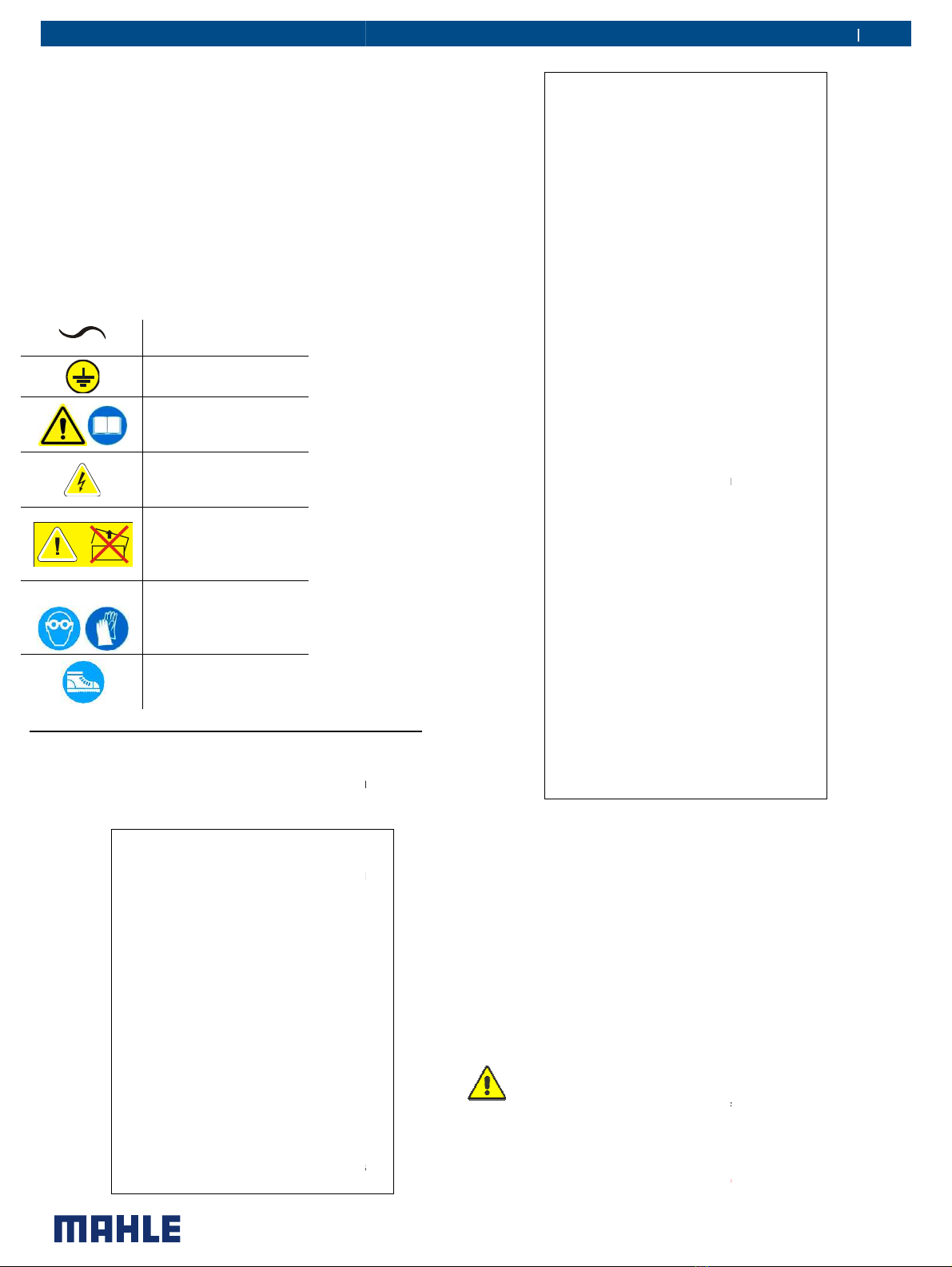
Symbols................................................... 6
3.2.1
Safety ............................................................... 6
3.3
Glossary .................................................. 6
3.4
Guidelines for the handling of refrigerant 6
3.4.1
recautions for refrigerant storage ................... 6
3.4.2
Conditions of refrigerant and system ............... 7
3.4.3
Recycling capacity ........................................... 7
4
roduct description ........................................ 7
4.1
Application .............................................. 7
4.2
Scope of delivery ..................................... 7
4.3
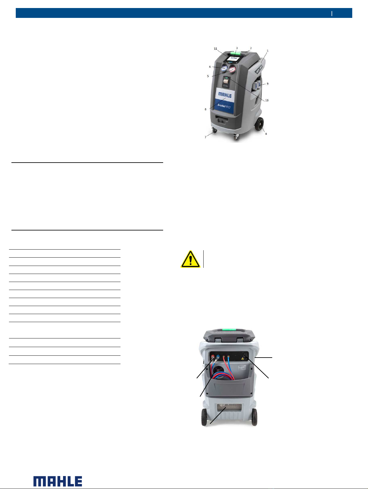
Description of the unit ............................. 7
4.4
User interface .......................................... 8
4.4.1
Main menu ........................................................ 9
4.5
E³ CONNECT quick couplers .................. 9
5
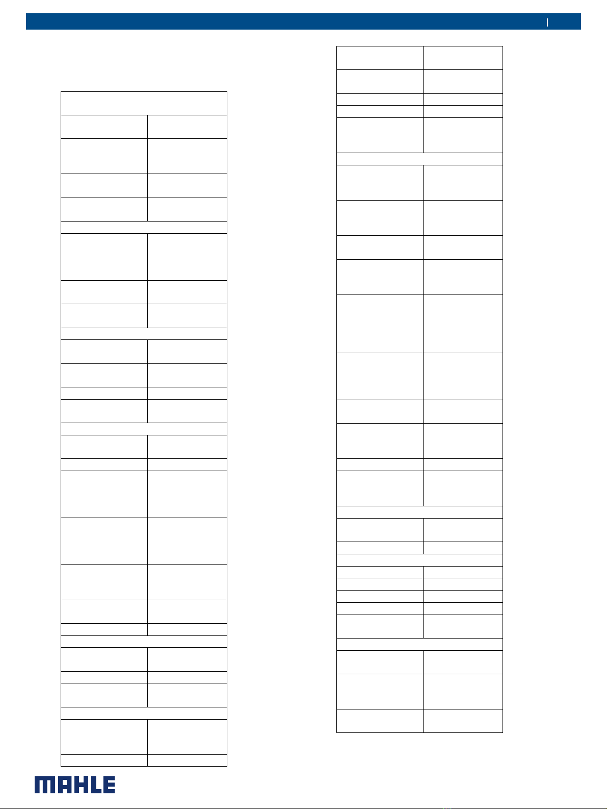
Technical features ........................................ 10
6
Installation.................................................... 11
6.1
Equipment installation ........................... 11
6.1.1
Unpacking ...................................................... 11
7
Commissioning............................................. 11
7.1
Connections .......................................... 11
7.1.1
ositioning and connection ............................ 11
7.2
Software update .................................... 12
7.3
Initial verification .................................... 12
7.4
New AG and OE oil bottles filling ...... 12
7.5
UV dye bottle filling ............................... 13
8
Setup ........................................................... 14
9
Service Menu
............................................ 15
9.1
Manual activations and analogue channel
view
............................................................... 15
9.2
ressures calibration (service kit)
.............. 15
9.3
OOB ressures calibration (service kit)
...... 16
9.4
Gas weight calibration
.............................. 16
9.5
Calibration check
..................................... 17
9.6
Oil weight calibration
................................ 17
9.7
Compressor and vacuum pump test
......... 17
9.8
Spare parts & consumables
...................... 17
10
Equipment
and simulator ........................... 17
11
Refrigerant fluid circuit
............................ 17
11.1
Refrigerant fluid circuit
............................. 17
11.2
Operational cycles
................................... 18
11.3
Receiving tank (refrigerant cylinder)
.......... 18
11.4
Manifold charts
....................................... 18
11.5
NITROGEN
TEST and FORMING GAS
LEAK TEST - MANIFOLD ..................................... 20
11.6
Suction circuit components
...................... 21
12
Non
-permanent junction .............................. 21
13
Electrical connections
............................. 21
14
Maintenance
............................................. 22
14.1
Maintenance interval
............................... 22
14.2
Hoses
emptying ..................................... 23
14.3
Air
purge ................................................ 23
14.4
Vessel
filling ........................................... 23
14.5
ressures
zero ....................................... 23
14.6
Self
leak test .......................................... 23
14.7
E³
UM
................................................ 23
14.8
ump
oil change .................................... 24
14.9
Dryer
filter change ................................. 24
14.10
Replacement
of Active Oil rotection
Cartridge .............................................................. 25
14.11
Calibration
check ................................... 25
14.12
Maintenance
of printer ........................... 25
14.13
eriodic
checks ..................................... 26
14.14
Refrigerant
type change (only for ACX 380)
.............................................................. 27
14.15
Air purge
................................................. 27
14.16
Counters
................................................ 27
14.17
Replacing white sample filter (Refrigerant
identification unit
).................................................... 27
15
Replacement interventions ........................... 28
15.1
Extraordinary maintenance list
................. 28
15.2
Extraordinary maintenance
...................... 28
15.2.1
Replacement of component connected
to refrigerant circuit
....................................................... 28
15.2.2
Replacement
of logic electronic board with
display .................................................................... 29
15.2.3
Replacement
of electronic power board .. 29
16
Spare and wearing parts
.............................. 30
16.1
Refrigerant identification unit
.................... 30
A ENDIX 1 – REFRIGERANT FLUID CIRCUIT
ACX380/480 ....................................................... 31
A ENDIX 2 – REFRIGERANT FLUID CIRCUIT
ACX380/480 O ERATIONAL CYCLES
............ 32
A ENDIX 3 – ACX380/480 - ELECTRICAL
CONNECTION – LOGIC ELECTRONIC BOARD
........................................................................... 36
A ENDIX 4 – ACX380/480 - ELECTRICAL
CONNECTION – OWER ELECTRONIC
BOARD AND OWER SU LY
....................... 37
A ENDIX 5 – ACX380/480 - ELECTRICAL
CONNECTION – STATUS AND WARNING
INDICATOR LIGHT ELECTRONIC BOARD ........ 39
A ENDIX 6 – TROUBLE SHOOTING .......................... 40
A ENDIX 7 – FAILURE LIST ACX380/480 .................. 41

|
ACX380/480
|
3
en
©MAHLE
1
General instructions
1.1
General notes
All rights reserved.
This manual may not be reproduced, in part or entirely,
either in printed or digital form.
It may be printed out solely for use by the user and
operators of the equipment to which it refers.
MAHLE and resources used for the drawing up of this
manual will not be held responsible for the incorrect use of
the manual while they guarantee that information in the
manual have been duly checked.
The product can be subject to changes and improvements.
MAHLE reserves the right to change without notice the
information contained in the manual.
1.2
General instructions
ressure equipment undergoes checks before
commissioning and periodical checks during operation, in
compliance with rules and law provisions in force in the
country where the tool is used.
The operator is responsible for operating the equipment in
conformity with local legislation.
Only for model ACX 380.
The equipment is designed for recovering and recycling
R1234yf/R134a refrigerant fluid from automotive A/C
system.
The equipment is intended to be used by automotive
and similar repair and service workshops.
The switch between the two refrigerant types, from
R134a to R1234yf, can only be performed by a
technician of an Authorised MAHLE Centre.
This equipment is intended solely for use by professionally
trained operators familiar with the basics of refrigeration,
refrigeration systems, refrigerants and the hazards
associated with pressurised equipment.
Careful reading of the present manual by the owners, the
users and the operators is required for a correct and safe
use of the tool.
The user shall not be entitled to open the product since
maintenance operations are reserved to the authorised
service centre.
1.3
Manufacturer identification
The ACX equipment is manufactured by:
MAHLE Aftermarket Italy S.p.A.
via Quasimodo 4/a, Italy
hone: +390521954411
1.4
Environmental precautions
Any service operation with the equipment must be carried
out being careful not to disperse fluorinated gases (R134a)
into the environment, in order to prevent the greenhouse
effect and the subsequent global warming of the planet. The
release of refrigerant gas R134a into the atmosphere is
forbidden by laws that were enacted within the framework of the
Kyoto protocol.
For information only, we will mention in particular, for the European
Union, REGULATION (EU) No 517/2014 OF THE EURO EAN
ARLIAMENT AND OF THE COUNCIL of 16 April 2014 on
fluorinated greenhouse gases and repealing Regulation (EC) No
842/2006.
The waste coming from the service activities must be placed in
collection centres foreseen by the enforced laws, they must not be
dispersed in the environment and they must not be disposed of with
urban waste.
2
Safety conditions
2.1
Personal safety information
2.1.1
Definitions
DANGEROUS AREAS:
Any area within or close to the equipment implying risk for the safety
and health of exposed persons.
EX OSED ERSON:
Any person completely or partially standing in a dangerous area.
O ERATOR:
The person/s charged with operating the machine for its intended
purpose.
CLASSIFICATION OF O ERATORS
The operator can be classified according to two main categories,
which, in some cases, refer to one single person:
•The operator charged with the equipment operation has the
duty to:
oStart up and monitor the machine's automatic cycle;
oCarry out simple setting operations;
oRemove the causes of equipment stop not implying
breakings of members but simple operating anomalies.
•Maintenance technician a technician trained by an authorised
MAHLE centre, capable of working on the machine’s
mechanical and electrical components with its guards open to
make adjustments and to service and repair it.
USER
Body or person legally responsible for the equipment.
2.1.2
Personal safety information
The A/C service station is particularly simple and reliable due to its
adjustments and functions. When used correctly it presents no
hazard for the operator, provided he observes the following general
safety instructions and that the service station is regularly serviced
(incorrect maintenance/use compromise the equipment's safety).
Before operating the service station for the first time, read these
instructions carefully. If any part of the instructions is unclear,
contact your reseller or MAHLE.
This service station may be used by only one equipment operator,
familiar with A/C and refrigeration systems and the hazards
associated with refrigerants and high pressure equipment.

| ACX380/4850 | 4en
WORK LACE: The station can work with both R134a and
R1234yf (the two refrigerants cannot be stored within the
station at the same time).
Refrigerant R1234yf is defined as flammable refrigerant.
Nonetheless, although refrigerant R134a is not defined as
flammable, mixtures of air or oxygen with R134a may
become flammable under very particular conditions.
The equipment must be operated outdoor or in a well-
ventilated location (at least 1 air change per hour). The
workshop has to be equipped with ventilation systems
able to ensure air change in every environment area or
carry out periodical ventilation by opening the areas.
Use the equipment away from heat sources or hot
surfaces. The equipment must not be used in explosion risk
environments (potentially explosive atmospheres). Before
using it, put the equipment on a levelled plane and secure
position, blocking it with suitable wheel stops.
Do not expose the tool to direct sunrays, heat sources, rain
and jets of water. Do not smoke near the equipment and
during operations (keep at a distance of at least 1 m).
The work area must be monitored by the operator while the
equipment is operating.
ATTENTION: R134a and/or R1234yf refrigerant
fumes/gases are heavier than air and can gather on the floor
or inside cavities/holes and cause choke by reducing the
oxygen available for breathing.
At high temperatures, the refrigerant breaks down releasing
toxic and aggressive substances, harmful for the operator
and the environment. Avoid inhaling the system coolants
and oils. Exposure can irritate eyes and the respiratory tract.
ELECTRICAL CONNECTION: Connect the power cord
solely to a mains supply which conforms to the ratings on
the machine's nameplate (mounted on its side). Make sure
the mains socket is grounded.
Maximum impedance allowed in the point of connection to
the mains shall comply with standard EN 61000-3-11.
Starting currents can cause short voltage drops, which may
affect other equipments under unfavourable conditions. If
impedance in the point of connection to the mains is not
compliant, this may lead to interference so please consult
the electrical power network operator before connecting the
equipment.
Never use the service station with a defective power cord or
a different one from that supplied with the machine. If
damaged, immediately have it replaced with an original
spare part or equivalent by a MAHLE centre. Before
opening the service station, extract completely the supply
cable from the plug, or you can get an electric shock.
Do not tamper with or bypass the safety equipment and
settings.
Do not leave the machine powered up when not in use; shut
off the power supply before leaving the equipment unused
for a long time. Do not forget that the tool (pressure tool) must
always be protected.
REFRIGERANTS AND LUBRICANTS - ERSONAL SAFETY
EQUI MENT AND RECAUTIONS: The refrigerants and the
pressure cylinders have to be handled with care, otherwise there will
be possible health risks.
The operator must wear safety glasses, gloves and protective
clothing suitable to the work. Contact with the refrigerant can cause
blindness (eyes) and other physical damages (freezing) to the
operator. Avoid contact with the skin; the refrigerant's low boiling
point (approx. –26 °C for R134a and approx. -30 °C for R1234yf) can
cause freezing burns.
Further information about safety can be obtained from the safety
sheets of lubricant and refrigerant producers.
Do not inhale refrigerant or oil vapour. Keep away from the vent
valves and ventilation coupling, especially when non-condensable
gas is being vented.
Never direct the quick couplings (taps) towards your face or other
persons or animals.
OTHER ROHIBITIONS AND USE LIMITATIONS: Only use pure
R134a or R1234yf refrigerants, refrain from using on vehicles
containing other types of refrigerants or mixtures of the two
refrigerants or other refrigerants. Mixture with other types of
refrigerant produces serious damage to the conditioning and cooling
systems. Mixed refrigerants have to be disposed of according to
the current regulations. Never use ACX equipment with systems
containing compressed air; mixtures of R134a or R1234yf with air or
oxygen may be potentially flammable.
Do not modify calibration of safety devices. Do not remove seals of
safety valves and of control systems. Do not use external tanks or
other storage containers that are not type-approved or without
safety valves.
Make sure the equipment's aeration and ventilation ports are not
obstructed or covered while the equipment is operating.
HOSE CONNECTIONS: Hoses may contain pressurised refrigerant.
Before changing the service couplers, check the respective
pressures in the hoses (pressure gauge).
Before connection to a car A/C system, to an external tank/cylinder,
check that the quick couplers are closed (unscrewed H and L
valves).
Scrupulously follow the instructions on the equipment's display.

©MAHLE
QUICK COU LERS CLOSING/O ENING:
MAINTENANCE/GENERAL CLEANING:
The equipment
has to be serviced at the intervals indicated by the
equipment itself.
The service station maintenance has to be performed
according to
the procedures described in this manual and
to the current safety regulations.
Use only MAHLE original parts.
When the equipment requires the drier filter and the vacuum
pump oil to be changed, you have to be careful in the
replacement.
A/C service station
maintenance can be carried out
exclusively by a trained operator or by a service man of a
MAHLE certified seller.
Do not use chemical agents for the service station cleaning
as they could attack the material or the surface.
STO FOR LONG ERIOD: Stor
e the equipment in a safe
place, disconnected from the mains, away from excessive
temperatures, humidity and the risk of damaging impact.
Contact the Technical Service to run a safety shutdown of
the equipment, and if scrapping the unit, to drain and
recyc
le the R134a or R1234yf refrigerant as required by
local legislation.
To resume operation, repeat the installation (there is no
need to register the unit anew on the website) and run the
commissioning trials and regular operational checks as
required by local legislation.
2.2
Important information on service
equipment safety
When using the equipment, the following operations are not
allowed as they might cause, under certain circumstances,
danger for persons and cause permanent damage to the
equipment itself.
-
Do not remove or make unreadable labels,
signs and/or dangers signs placed on the
equipment and in the area nearby.
-
Do not disable the unit's safety equipment.
-
The electrical system to which the service
equipment is connected must be configured as
provided by local legislation.
Closing (detach from
the vehicle):
counter clockwise
Opening (connect to
the vehicle):
clockwise
The equipment
has to be serviced at the intervals indicated by the
The service station maintenance has to be performed
the procedures described in this manual and
When the equipment requires the drier filter and the vacuum
pump oil to be changed, you have to be careful in the
maintenance can be carried out
exclusively by a trained operator or by a service man of a
Do not use chemical agents for the service station cleaning
e the equipment in a safe
place, disconnected from the mains, away from excessive
temperatures, humidity and the risk of damaging impact.
Contact the Technical Service to run a safety shutdown of
the equipment, and if scrapping the unit, to drain and
le the R134a or R1234yf refrigerant as required by
To resume operation, repeat the installation (there is no
need to register the unit anew on the website) and run the
commissioning trials and regular operational checks as
When using the equipment, the following operations are not
allowed as they might cause, under certain circumstances,
danger for persons and cause permanent damage to the
Do not remove or make unreadable labels,
signs and/or dangers signs placed on the
Do not disable the unit's safety equipment.
The electrical system to which the service
equipment is connected must be configured as
-
Only operators or qualified staff instructed or
certified for the
equipment
open the equipment
. The equipment
parts which can cause electrocution: shut off
power to the equipment before
servicing/repairing it.
2.3
Safety devices
The A/C service station
is equipped with the following safety
devices:
SAFETY RESSURE SWITCH
in case of excessive pressure.
SAFETY VALVE:
The safety valve opens when the
pressure inside the system reaches a level higher than the
fixed limits.
MAIN SWITCH:
Switches the equipment off by
interrupting the power supply. It is advisable to pull the
power cord plug out of the mains socket in any case
before starting maintenance work.
ANY TAM ERING WITH THE ABOVE
SAFETY DEVICES IS ROHIBITED.
Failur
e to observe any of the above safety instructions voids the
equipment's warranty.
3
Layout of the manual
3.1
Use of the manual
This manual is an integral part of the equipment and
must be kept in the equipment's immediate vicinity by
the purchaser
•
This manual shall accompany the equipment in case this is
passed on to a new user.
•
The content of this manual has been drawn up in
compliance with the guide lines of the UNI standard
10893:2000.
•
Diffusion, modification or use of this manual for own aims is
forbidden.
•
The manual uses symbols which call the reader's attention
to specific points to facilitate its use.
•
It includes all technical, operating, shutdown, maintenance,
spare parts and safety information.
•
In case of doubts on the correct interpretation
instructions, please contact our technical service to obtain
the required clarifications.
Operations which are potentially hazardous for the
operator are highlighted with this symbol.
Such operations can cause serious injury.
Operations
requiring special attention are highlighted with
this symbol.
Such operations shall be carried out correctly to avoid
|
ACX380/480
|
5
en
Only operators or qualified staff instructed or
equipment
maintenance can
. The equipment
contains
parts which can cause electrocution: shut off
power to the equipment before
is equipped with the following safety
SAFETY RESSURE SWITCH
: It stops the compressor
The safety valve opens when the
pressure inside the system reaches a level higher than the
Switches the equipment off by
interrupting the power supply. It is advisable to pull the
power cord plug out of the mains socket in any case
before starting maintenance work.
ANY TAM ERING WITH THE ABOVE
-
MENTIONED
SAFETY DEVICES IS ROHIBITED.
e to observe any of the above safety instructions voids the
Layout of the manual
This manual is an integral part of the equipment and
must be kept in the equipment's immediate vicinity by
This manual shall accompany the equipment in case this is
The content of this manual has been drawn up in
compliance with the guide lines of the UNI standard
Diffusion, modification or use of this manual for own aims is
The manual uses symbols which call the reader's attention
to specific points to facilitate its use.
It includes all technical, operating, shutdown, maintenance,
spare parts and safety information.
In case of doubts on the correct interpretation
of the
instructions, please contact our technical service to obtain
Operations which are potentially hazardous for the
operator are highlighted with this symbol.
Such operations can cause serious injury.
requiring special attention are highlighted with
Such operations shall be carried out correctly to avoid

causing damage to objects or to the surrounding
environment. This symbol also highlights information to
which special attention must be paid.
Operations which require careful reading of the manual's
instructions are highlighted with this symbol.
3.2
Symbols
This paragraph describes the safety symbols which may be
posted on the service equipment.
3.2.1
Safety
ALTERNATING
CURRENT
SAFETY GROUNDING
CONSULT THE
INSTRUCTIONS
MANUAL
ATTENTION!
ELECTROCUTION
HAZARD
CAUTION !: DO NOT
REMOVE THE COVER
(maintenance
technicians only)
USE ROTECTIVE
GLOVES
WEAR ROTECTIVE
GOGGLES
USE ANTI
-
SMASH
SAFETY SHOES
3.3
Glossary
To make the reading of this manual easier, we have
prepared the list of the most important technical terms used
in the manual.
Refrigerant:
Refrigerant fluid used in
advanced motor vehicle A/C systems.
The following refrigerant fluids
may be used:
•R-1234yf
CH2CFCF3 2,3,3,3
Tetrafluoropropene.
•R-134a C2H2F4 -
1,1,1,2
Tetrafluoroethane
A/C system: air conditioning system.
Equipment: A/C service
station for
recovering, recycling,
draining and
charging the A/C system.
External tank:
Refrigerant bottle used to
fill the internal tank.
Internal cylinder:
cylinder for refrigerant
storage.
|
ACX380/4850
causing damage to objects or to the surrounding
environment. This symbol also highlights information to
Operations which require careful reading of the manual's
instructions are highlighted with this symbol.
This paragraph describes the safety symbols which may be
To make the reading of this manual easier, we have
prepared the list of the most important technical terms used
Refrigerant fluid used in
advanced motor vehicle A/C systems.
The following refrigerant fluids
CH2CFCF3 2,3,3,3
-
1,1,1,2
-
station for
draining and
Refrigerant bottle used to
cylinder for refrigerant
hase:
erformance of a single function.
Cycle: Sequence of steps.
Recovery: Extraction of
refrigerant from
the vehicle.
Recycling:
Cleaning of refrigerant,
includes: separating out oils, removal of
non-
condensable gas and
single/multiple pass through filters to
reduce humidity, acidity and particulate
content of the fluid.
Disposal: disposal
of refrigerant for
storage followed by
destruction/scrapping by an authorised
waste management centre.
Vacuum cycle:
Draining out of a motor
vehicle A/C system and separation out of
condensed matter and humidity, using
only the vacuum pump.
Oil charge: C
harge of oil into an A/C
system to ensure the correct charge as
specified by the vehicle's manufacturer.
Charge:
filling of refrigerant into the A/C
system in the amount specified by the
manufacturer.
System flushing:
Cleaning phase for the
removal of po
ssible polluting substances
from the A/C system or parts of it.
Non condensable gas:
stored in gaseous phase, including air
and nitrogen.
3.4
Guidelines for the handling of refrigerant
3.4.1
Precautions for refrigerant storage
The refrigerant
removed from the A/C system must be handled with
care to prevent or minimise the risk of mixing with other refrigerants.
This machine is suitable for treating R134a or R1234yf
refrigerants, individually (not simultaneously).
The external cylinders used to
store the refrigerants must be clearly
marked to prevent mixing different refrigerants.
Cylinders shall be free from oil or other contaminants and clearly
marked so as to identify the refrigerant contained.
ATTENTION:
when handling, using and storing
R-1234yf
refrigerant and dealing with emergency
situations, MAKE SURE
to refer to the product’s safety
sheet.
GET THE SAFETY SHEET FROM YOUR REFRIGERANT
SU LIER AND FOLLOW ITS INSTRUCTIONS.
REFRIGERANT R1234YF IS DEFINED AS FLAMMABLE
ACX380/4850
|6en
erformance of a single function.
refrigerant from
Cleaning of refrigerant,
includes: separating out oils, removal of
condensable gas and
single/multiple pass through filters to
reduce humidity, acidity and particulate
of refrigerant for
storage followed by
destruction/scrapping by an authorised
Draining out of a motor
vehicle A/C system and separation out of
condensed matter and humidity, using
harge of oil into an A/C
system to ensure the correct charge as
specified by the vehicle's manufacturer.
filling of refrigerant into the A/C
system in the amount specified by the
Cleaning phase for the
ssible polluting substances
from the A/C system or parts of it.
Refrigerant
stored in gaseous phase, including air
Guidelines for the handling of refrigerant
Precautions for refrigerant storage
removed from the A/C system must be handled with
care to prevent or minimise the risk of mixing with other refrigerants.
This machine is suitable for treating R134a or R1234yf
refrigerants, individually (not simultaneously).
store the refrigerants must be clearly
marked to prevent mixing different refrigerants.
Cylinders shall be free from oil or other contaminants and clearly
marked so as to identify the refrigerant contained.
when handling, using and storing
R
-
134a
or
refrigerant and dealing with emergency
to refer to the product’s safety
GET THE SAFETY SHEET FROM YOUR REFRIGERANT
SU LIER AND FOLLOW ITS INSTRUCTIONS.
REFRIGERANT R1234YF IS DEFINED AS FLAMMABLE

|
ACX380/480
|
7
en
©MAHLE
REFRIGERANT.
3.4.2
Conditions of refrigerant and system
The condition of the refrigerant is critical to the operation of
the vehicle's A/C system. Running repairs properly following
failure or damage safeguards the quality of the refrigerant
itself (particulates, acids and water).
3.4.3
Recycling capacity
The service equipment's filtering systems must be replaced
regularly (see maintenance messages) to ensure effective
recycling.
4
Product description
4.1
Application
A/C service station is suitable for vehicle with A/C systems
using R134a or R1234yf.
The following functions can be implemented:
•Refrigerant recovery and recharging.
•Vacuum generation.
•Flushing.
4.2
Scope of delivery
Description
Service hose (high pressure)
Service hose (low pressure)
Quick-release coupling (high pressure)
Quick-release coupling (low pressure)
New AG oil bottle
Used oil bottle
UV dye bottle
New OE oil bottle
Original instructions
Adapter for external bottle
connection
Funnel
Safety goggles
Safety gloves
4.3
Description of the unit
Fig.1: Left-Front view
1
Rear Handle
2
Tool Tray
3
Status light
4
Low ressure Gauge
5
High ressure Gauge
6
Front Cover
7
Locking Caster
8
Rear Wheel
9
New & Used Oil Bottles
10
rinter
11
Touch screen
DO NOT USE THE UNIT UNLESS THE CHARGING
HOSES (H – L ) ARE CORRECTLY CONNECTED
Fig. 2: Rear view (detail)
1
Fan
2
Vents
3
ower cord connector and ower switch
4
H &L quick couplers and hoses
5
Nitrogen inlet
1
4
2
3
5

| ACX380/4850 | 8en
Fig. 3: Right-front view (detail)
1
High-pressure gauge
2
Low-pressure gauge
3
Display with Touch screen and USB port
The pressure gauges (Fig. 3, os. 1, 2) of the display and
operating unit are used to monitor the pressure during the
individual vehicle A/C service phases. The status of the
various service phases during maintenance is displayed
on the touch screen (Fig. 3, os. 3).
The menu selection and the necessary entries are made
on the touch screen (Fig. 3, os. 3). MAHLE provides a
USB stick for ACX station to activate an additional
database (e.g. Agri&Work machinery). The USB stick can
be inserted in the USB type A port on touch screen frame
(Fig. 3, os. 3).
4.4
User interface
All settings, controls and service functions are available on
the touch screen display. It also displays the service
equipment’s status, the progress of A/C system service and
any alarms and warning/error messages.
The touch screen is the basic operator interface and can be
operated with the fingers. When a button is pressed, a beep
sounds.
The following icons are available on the display:
Icon
Description
Device
connected via
WiFi
The residual
refrigerant weight
(in kg and with
visual bar)
to enable/disable
the bar by
vertically swiping
your finger from
top to bottom
Remote
connection “RE
SOLVE” active
Icon to send
email via WiFi
Icon to print
report via the unit
printer
Icon to print via
WiFi on a
network printer
document in the
print queue
Icon to start cycle
Recovered
refrigerant
amount
Amount of
refrigerant to be
injected
Recovered oil
amount
Amount of oil to
be injected
Amount of UV
dye injected
Vacuum time
Vacuum test time
Function or cycle
disabled
Function or cycle
enabled
Icon to update
list
Low light
intensity
High light
intensity
To select a function in the menu press the text name of the function,
the selection occurs when the finger is released.
If there are functions that need more space on the screen page, for
example: the additional functions or maintenance list, to display the
different entries, it is necessary to horizontally swipe on the display,
or in case of setup it is possible to display the different entries by
moving the scroll bar on the display with the finger. Lift the finger
when you are on the desired position.
Horizontal swipe gesture on
touch screen
1
2
3

|
ACX380/480
|
9
en
©MAHLE
If you need to enter free text or identify a set of data, a
keypad automatically appears (for example, for entering
workshop data or at the end of the service cycle).
Status Light (Fig. 1, os. 3)
The station with the status light on the top communicates
based on the following modes:
•Flashing green: procedure in progress.
•Steady green: procedure completed successfully.
•Steady red: operator presence required.
4.4.1
Main menu
The Main menu of the graphical user interface allows to
select the following functions:
•Vehicle selection
•OneClick
•Cycles
•Additional Functions
•Maintenance
•Setup
•Secured Service (not available for user; reserved
only for customer service personnel)
Each function will be described in the next chapters.
4.5
E³ CONNECT quick couplers
E³ CONNECT is the INTELLIGENT COU LER, that with the
suitable automated procedure in the software enables to:
•reduce the non condensable gas formation inside
the cylinder ;
•avoid refrigerant dispersion in the air during
disconnection (puff effect);
•check possible SCHRADER valve leaks before
disconnection.

| ACX380/4850 | 10 en
5
Technical features
Cylinders for R134a or R1234yf
fluids
R134a or R1234yf
cylinder capacity
20 l
Maximum
operating
pressure ( S)
20 bar
ED category
(Dir.2014/68/EU)
III
Weight of
refrigerant content
Scale
Safety valve
Type
AIRTEK
-
VS14N T20HN
BR ED4 20bar
R 1/4 N T
Calibration
pressure
20 bar
ED category
(Dir.2014/68/EU)
IV
Containers for oil and detection
dye
Recovered AG
oil container
250 ml
New AG oil
container
250 ml
UV Dye container
250 ml
New OE oil
container
250 ml
neumatic circuit
Vacuum pump
flow rate
100 l/min double
stage
Vacuum level
0.02 mbar
Vacuum pump oil
life
60h
–
extensible
to max 1000 h
with E
3
UM
procedure
Refrigerant
recovery
compressor cubic
capacity
14 cc
Drier filter
Every 150Kg of
refrigerant
recovered
Non condensable
gas discharge
Automatic, with
solenoid valve
H and L taps
Automatic
Safety pressure switch
Type
13/18bar
1/4SAE
Trip pressure
18 bar
ED category
(Dir.2014/68/EU)
IV
neumatic fittings
Net length of
external H and
L hoses
4.5 m
H and L
Analog 80 mm,
pressure gauges
pulse
-
free, 1.0
class
Display
Touch screen
7” TFT colours
Keypad
Touch screen
Software updating
Via Wi
-
Fi
rinter
via Nexusprint
software or via
thermal printer
Functions and features
Recovered oil
measurement
Automatic
weighing, 1 g
res., 5 g acc.
New oil automatic
charge
With automatic
scale, 1 g res.,
5g acc.
UV dye automatic
charge
Timed
Electric
compressor
function
With integrated
flushing function
Flushing
Flushing
available with
external
accessory
(option)
Database
Complete
electronic (cars
and industrial
vehicles only)
AC erformance
Test
Manual and
automatic
Recovered oil
measurement
Automatic
weighing, 1 g
res., 5 g acc.
Sound level
< 70 dB (A)
Battery type for
internal Real time
clock
Lithium CR
-
2032 3V
180mAh 3g.
Overall dimensions
WxDxH
700 x
750 x
1100 mm
Loadless weight
about 85 kg
ower supply
Frequency
50 Hz
Voltage
230 V ~
ower
800 W
rotection
Thermal
Installation
category
II
Environmental conditions
Operating
temperature
10
-
50°C
Humidity
10
-
90% R.H.
(non
condensing)
Ambient
pressure
75 k a until 106
k a

©MAHLE
6
Installation
6.1
Equipment installation
6.1.1
Unpacking
Warning –
Risk of personal injury! Incorrect handling could
cause equipment to overturn.
RISK OF OVERTURNING
The manufacturer disclaims all responsibility for
damage
to objects and/or persons resulting from the equipment
being wrongly removed from the pallet, or from the
operation being made by unsuitable personnel, with
improper means/protections and without complying with
the existing laws on manual handling o
f loads and with
the operations described in this manual.
Remove the metal
staples for wood
and open the
carton box
Remove the cap
and carton box
Cut the plastic straps that connect unit
to the pallet
Remove the packaging of the unit.
Remove the equipment from the pallet (operators ar
required)
Keep the pallet, carton and scratch protection film
for use when returning the unit. The unit
rolls on wheels;
the two front wheels can be locked.
A/C service station is supplied with the intern
al refrigerant
tank empty. This prevents problems in shipping
the unit
Risk of personal injury! Incorrect handling could
damage
to objects and/or persons resulting from the equipment
being wrongly removed from the pallet, or from the
operation being made by unsuitable personnel, with
improper means/protections and without complying with
f loads and with
Remove the equipment from the pallet (operators ar
e
Keep the pallet, carton and scratch protection film
rolls on wheels;
al refrigerant
the unit
.
REFRIGERANT SCALE SCREW RELEASE
The unit is transported, with the scale blocked by a locking screw to
avoid damaging the load cell.
The scale locking screw is placed on
the
equipment bottom side (see the box shown above) and is
formed by a bolt.
For commissioning, unscrew the screw.
7
Commissioning
7.1
Connections
The unit has to be positioned on a horizontal surface to ensure the
correct operation.
The unit has to be connect
ed to the electric mains following
instructions on t
he identification plate of the unit applied next to the
main switch, mainly as to applicable voltage and power.
The A/C service stations
are designed for 230VAC, 50Hz.
Follow the information on
the rating plate.
7.1.1
Positioning and connection
HANDLING:
During handling, the minimum devices required
for correct handling shall be ensured, as provided for by
accident prevention provisions.
OSITIONING:
lace the unit in a stable place. The location
must be well ventilated, with a good rate of change of air.
The unit must be located at least 10 cm from any potential
obstacles to its internal ventilation.
rain and excessive humidity as they can irreparably damage
it.
In addition, the equipment must never be directly exposed
to the sunrays or to excessive dust.
INSTALLATION:
the unit must be installed by a
technician
in scrupulous observance of in accordance with
electrical engineering principles. The use of the equipment in
explosive atmosphere is forbidden.
CONNECTIONS:
since the unit is connected to the main
power supply, it must be properly grounded with its pow
plug GND pin. Failure to ground the unit can damage it and
constitutes a risk of fatal injury to the operator. osition the
unit so that the power plug is easy for the operator to
access.
|
ACX380/480
|
11
en
REFRIGERANT SCALE SCREW RELEASE
The unit is transported, with the scale blocked by a locking screw to
The scale locking screw is placed on
equipment bottom side (see the box shown above) and is
For commissioning, unscrew the screw.
The unit has to be positioned on a horizontal surface to ensure the
ed to the electric mains following
he identification plate of the unit applied next to the
main switch, mainly as to applicable voltage and power.
are designed for 230VAC, 50Hz.
the rating plate.
Positioning and connection
During handling, the minimum devices required
for correct handling shall be ensured, as provided for by
lace the unit in a stable place. The location
must be well ventilated, with a good rate of change of air.
The unit must be located at least 10 cm from any potential
obstacles to its internal ventilation.
Keep the unit away from
rain and excessive humidity as they can irreparably damage
In addition, the equipment must never be directly exposed
to the sunrays or to excessive dust.
the unit must be installed by a
specialized
in scrupulous observance of in accordance with
electrical engineering principles. The use of the equipment in
explosive atmosphere is forbidden.
since the unit is connected to the main
power supply, it must be properly grounded with its pow
er
plug GND pin. Failure to ground the unit can damage it and
constitutes a risk of fatal injury to the operator. osition the
unit so that the power plug is easy for the operator to

Fig. 4: Rear view (detail)
1
ower cord connector and ower switch
2
H &L vehicle connector/couplers and hoses
ATTENTION:
Leave the quick coupling taps closed
when the unit is not in use and at the end of vehicle
service operations.
7.2
Software update
It is possible to check for software updates via Wi-
Fi and
download them inside the
•Main Menu
oSetup
Updates Chec
7.3
Initial verification
Execute the following actions in sequence by following the
display guided procedure and th
e illustrations on the
of the equipment:
•Gas weight verification
•Oil weight verification
•First vessel filling
It is possible to interrupt the initial verification, the station
will propose at next powering to continue.
The equipment cannot operate until all the steps of
initial verification have been completed.
CAREFULLY ABIDE BY THE
FOLLOWING INSTRUCTIONS TO
AVOID DANGER TO ERSONS, THE
DISCHARGE OF REFRIGERANT IN
THE ATMOS HERE
2
1
|
ACX380/4850
Leave the quick coupling taps closed
when the unit is not in use and at the end of vehicle
Fi and
Execute the following actions in sequence by following the
e illustrations on the
screen
It is possible to interrupt the initial verification, the station
The equipment cannot operate until all the steps of
the
Let us consider as first filling the one carried out during the initial
check with internal tank of the equipment free of refrigerant and
containing air.
Set the quantity of refrigerant to fill (at least 3 kg) and follow the
guided procedure shown on the display.
Check that the equipment hoses are not connected and positioned
in the hose winder. Start the procedure that initially implies the
creation of vacuum in the internal tank. This phase will take 15
minutes and will act on the whole equipment.
Only when the message appears asking to connect the charge tank,
connect the L quick coupler (colour
blue
refrigerant tank using the supplied adaptor.
When the message occurs open the coupler by turning the knob
clockwise. Open the valve on the external tank.
Just right before reaching the planned quantity of refrigerant, the
unit will stop and ask the user to close the external refrigerant tank.
Then, the device will continue the recovery from the hoses and ends
when these are empty. Hence, it is necessary to
coupler and disconnect it
from the external tank.
Thanks to the E³ CONNECT function, the refrigerant
between the cylinder fitting and the hose quick
of the process -
will not be released in the enviro
There may be two types of source tanks: with plunger and without
plunger.
Tanks with plunger
shall remain upright to be able to transfer liquid
refrigerant; for this type of tanks connect to the L (liquid) coupler.
Tanks without plunger have only on
e valve, so they must be turned
upside down to transfer the liquid refrigerant.
The L
gauge indicates the pressure inside the external tank.
After some minutes the unit will automatically end the function.
At the end the weight of the charged
refrigerant will be displayed.
7.4
New PAG and POE oil bottles filling
To fill the new oil bottles (Fig.1 os. 9) they have to be extracted
from their housing by means of the quick coupler on the top of the
bottle; slightly press downward the coupler ring n
Fill the bottle by paying special attention to the “Active Oil
rotection” system.
•
During the oil suction phase, before entering the bottle air is
made dry as it pa
sses through a path of special “desiccant”
material.
•The
air inside the bottle is therefore completely “dry”
ACX380/4850
|12 en
Let us consider as first filling the one carried out during the initial
check with internal tank of the equipment free of refrigerant and
Set the quantity of refrigerant to fill (at least 3 kg) and follow the
Check that the equipment hoses are not connected and positioned
in the hose winder. Start the procedure that initially implies the
creation of vacuum in the internal tank. This phase will take 15
minutes and will act on the whole equipment.
Only when the message appears asking to connect the charge tank,
blue
) of the unit to an external
refrigerant tank using the supplied adaptor.
When the message occurs open the coupler by turning the knob
clockwise. Open the valve on the external tank.
Just right before reaching the planned quantity of refrigerant, the
unit will stop and ask the user to close the external refrigerant tank.
Then, the device will continue the recovery from the hoses and ends
when these are empty. Hence, it is necessary to
open the L quick-
from the external tank.
Thanks to the E³ CONNECT function, the refrigerant
- usually kept
between the cylinder fitting and the hose quick
-coupler until the end
will not be released in the enviro
nment.
There may be two types of source tanks: with plunger and without
shall remain upright to be able to transfer liquid
refrigerant; for this type of tanks connect to the L (liquid) coupler.
e valve, so they must be turned
upside down to transfer the liquid refrigerant.
gauge indicates the pressure inside the external tank.
After some minutes the unit will automatically end the function.
refrigerant will be displayed.
New PAG and POE oil bottles filling
To fill the new oil bottles (Fig.1 os. 9) they have to be extracted
from their housing by means of the quick coupler on the top of the
bottle; slightly press downward the coupler ring n
ut to extract it.
Fill the bottle by paying special attention to the “Active Oil
During the oil suction phase, before entering the bottle air is
sses through a path of special “desiccant”
air inside the bottle is therefore completely “dry”

|
ACX380/480
|
13
en
©MAHLE
After filling, close the bottle and place it back in its seat.
7.5
UV dye bottle filling
The UV Dye is a substance made up of a yellow-green
coloured fluorescent pigment, which means that, when lit by
an ultraviolet lamp, it becomes fluorescent and thus visible.
The UV dye can therefore be used to detect leaks of a small
entity inside the auto vehicle A/C system.
To fill the UV dye bottle (Fig.1 os. 9) it has to be extracted
from its housing by means of the quick coupler on the top
of the bottle; slightly press downward the coupler ring nut
to extract it.
Fill the bottle by paying special attention to the “Active Oil
rotection” system.
•During the oil suction phase, before entering the bottle
air is made dry as it passes through a path of special
“desiccant” material.
•The air inside the bottle is therefore completely “dry”
After filling, close the bottle and place it back in its seat.

| ACX380/4850 | 14 en
8
Setup
From the SETU menu it is possible to select parameters
and activations before starting cycle:
Wi-Fi
•by selecting this entry, the user may check and select
the Wi-Fi networks available and connect the station
via Wi-Fi.
RINT
•by selecting this entry, the user can select the print
options, such as:
Start print queue;
Delete print queue;
How to print (instructions);
rint test.
To print are available two printing modes are
available: using the printer of the station if
available or, for all models, via Wi-Fi using the
printer software named Nexus rint to be installed on C
with Windows 7 or later.
U DATE
•by selecting this entry, the user may check if software
updates are available and download them. Updates
Check starts with this icon
BRIGHTNESS
•by selecting this entry, the user can modify the
brightness of touchscreen display and Status Led.
MAINTENANCE COUNTERS
•by selecting this entry, the user may check the status of
station counters and consumables counters.
ACCOUNT
•by selecting this entry, the user can fill in the garage
data to be printed at the bottom of the cycle report.
LANGUAGE
•by selecting this entry, any language present in the
database may be set. In case you choose a language
with unintelligible characters: switch off the equipment,
press and hold the touch screen while switching on the
equipment, you will be directed to the language setting
menu.
RESOLVE
•by selecting this entry, the user can connect the station
to the server via Wi-Fi to allow remote control service
session by the dealer. The system will give an ID
number and a IN code to give to dealer.
SYSTEM INFORMATION
•selecting this entry, the user can check the station data.
DATE AND TIME
•selecting this entry, the user can change and save the date and
time.
NOTIFICATIONS
•by selecting this entry, the user can check the notifications
received by reseller for A/C service station.
LICENSES
•by selecting this entry, the user can check the licenses enabled
on the station.
SETTINGS
•selecting this entry, the user can enable specific functions (e.g.
Refrigerant analysis).
CREDITS
•by selecting this entry, the user can read the terms of the
licenses of the software.
MAHLE reserves the right to add new parameters to make
the equipment increasingly versatile and adaptable to
market’s needs.

©MAHLE
9
Service Menu
To carry out
calibration the service kit (tooling set)
described at chapter 10 is required.
9.1
Manual activations and analogue
channel view
From the SECURED
SERVICE menu, (insert the password
“DEBUG”), select
MANUAL ACTIVATIONS and press
START, insert the password “DEBUG”, press
RETURN and
then enter OK.
This submenu allows controlling the actuators and displays
all measurements.
Fig. 15: Manual activations screen
As shown in the picture the activated actuators are
highlighted with green
background colour. If deactivated
the colour is red.
The corresponding chart can be found in the
A ENDIX
At the bottom you can select the following functions:
•neumatic schema
•
Screen rotation (useful if the front door is open)
•Close menu (red square)
Manual Activation Key
(in bold the names
used in this manual)
Actuators of
the neumatic
Schema (see
A ENDIX 1)
ower Board
Output
(see
A ENDIX
A
-
S13
A1, A2
OUT A
R
-
S10
R1,
R2
OUT R
L
-
S62
L1
OUT L1
T
-
S61
T1
OUT T1
S
-
S60
S
OUT S
I
-
S15
I
OUT I
N
-
S8
N
OUT N
V1
-
N3
V1, V2, V
OUT
V
C
-
N1
C
OUT C
L2
L2
OUT L2
H
H
OUT H
N
IN
X
OUT X
N
OUT
T2
OUT T2
calibration the service kit (tooling set)
Manual activations and analogue
SERVICE menu, (insert the password
MANUAL ACTIVATIONS and press
RETURN and
This submenu allows controlling the actuators and displays
background colour. If deactivated
A ENDIX
.
At the bottom you can select the following functions:
Screen rotation (useful if the front door is open)
ower Board
(see
A ENDIX
4)
9.2
Pressures
calibration (service kit)
From the SECURED SERVICE menu,
(insert the password “DEBUG”),
select RESSURE CALIBRATION
and press START
messages, and enter OK to confirm.
Disconnect the L and H quick couplers from any A/C system and
press enter OK.
Wait
some minutes until the sentence “Emptying hoses” di
Then the message asks to
connect to L hose the
adapter
(alone, not connected to the bottle)
station accessories kit; when the next message is displayed,.
Fig. 16: LP quick coupler opening
Turn the L quic
k coupler clockwise to open it and press enter OK
so that air gets into the L hose
Wait for the message to connect the reference gauge contained in
the service kit
and, by rotating L counter clockwise, close and
remove the bottle fitting adapter.
WARNING:
BE SURE BEFORE TO CONFIRM, THAT BOTTLE FITTING
ADA TER HAS BEEN REMOVED FROM L QUICK COU LER.
Connect to H coupler the reference
gauge present in the SERVICE
KIT, open the H
quick coupler by rotating it clockwise and press
enter OK.
WARNING:
ATTENTION NOT TO OINT THE
REFERENCE
ONESELF OR OTHER EO LE UNTIL ONE HAS THE ABSOLUTE
CERTAINTY THAT THE
CONNECTION WITH THE QUICK COU LER
IS SAFE.
O EN THE TA OF THE QUICK COU LER BY OINTING THE
GAUGE TOWARDS THE GROUND,
ALWAYS KEE THE GAUGE
TOWARDS THE GROUND EXCE T WHEN THE GUIDED
ROCEDURE REQUIRES ENTERING THE VALUE DIS LAYED ON
THE SAM LE GAUGE.
Fig. 17: Reference gauge connection
Fig. 18
:
|
ACX380/480
|
15
en
calibration (service kit)
(insert the password “DEBUG”),
and press START
, read the
Disconnect the L and H quick couplers from any A/C system and
some minutes until the sentence “Emptying hoses” di
sappears.
connect to L hose the
bottle fitting
(alone, not connected to the bottle)
, included in the ACX
station accessories kit; when the next message is displayed,.
k coupler clockwise to open it and press enter OK
Wait for the message to connect the reference gauge contained in
and, by rotating L counter clockwise, close and
BE SURE BEFORE TO CONFIRM, THAT BOTTLE FITTING
ADA TER HAS BEEN REMOVED FROM L QUICK COU LER.
gauge present in the SERVICE
quick coupler by rotating it clockwise and press
REFERENCE
GAUGE TOWARDS
ONESELF OR OTHER EO LE UNTIL ONE HAS THE ABSOLUTE
CONNECTION WITH THE QUICK COU LER
O EN THE TA OF THE QUICK COU LER BY OINTING THE
ALWAYS KEE THE GAUGE
TOWARDS THE GROUND EXCE T WHEN THE GUIDED
ROCEDURE REQUIRES ENTERING THE VALUE DIS LAYED ON
:
Reference gauge reading

| ACX380/4850 | 16 en
Measure the pressure reached by the reference gauge and,
insert the value on the screen of ACX unit when required by
software and press enter OK.
Subsequently the equipment will execute the vacuum, at
the end of which one will be asked to check that the gauge
reaches -1 bar, when requested by the guided procedure
press enter OK to confirm calibration.
9.3
OOB Pressures calibration (service
kit)
This function is possible to do only before to carry out the
First Vessel Filling (before to fill refrigerant) if the station
showed problems on the pressure measures.
From the SECURED SERVICE menu, (insert the password
“DEBUG”), select OOB RESSURE CALIBRATION and
press START, read the messages, and enter OK to confirm.
Disconnect the L and H quick couplers from any A/C
system and press enter OK.
Then the message asks to connect to L hose the bottle
fitting adapter (alone, not connected to the bottle), included
in the ACX station accessories kit; when the next message
is displayed.
Fig. 16: LP quick coupler opening
Turn the L quick coupler clockwise to open it and press
enter OK so that air gets into the L hose.
Wait for the message to connect the reference gauge
contained in the service kit and, by rotating L counter
clockwise, close and remove the bottle fitting adapter.
WARNING:
BE SURE BEFORE TO CONFIRM, THAT BOTTLE FITTING
ADA TER HAS BEEN REMOVED FROM L QUICK
COU LER.
Subsequently the equipment will execute the vacuum, at
the end of which one will be asked to check that the gauge
reaches -1 bar, when requested by the guided procedure
press enter OK to confirm calibration.
9.4
Gas weight calibration
From the SECURED SERVICE menu, (insert the password
“DEBUG”), Select the “Gas Weight calibration” follow the
instruction on the screen.
The reference weight need to be ≥ 4 kg max 22 kg (advised
from 8 to 20 kg) to be placed on the arm connected above the
load cell.
Fig. 14: cylinder
disconnected
Disconnect the vessel from
the scale.
Lift it and insert the spacer
under the vessel/cylinder
Fig. 15: cylinder re
-
connected
with arm
Re-connect the vessel/cylinder to
the scale. Insert the arm below
the vessel/cylinder.
Fig. 16: Reference weight on the arm
lace the reference weight on the top of the arm (i.e. 5 kg on
drawing above)

|
ACX380/480
|
17
en
©MAHLE
9.5
Calibration check
The refrigerant gas weight scale is calibrated with a 3 points
procedure during manufacturing and it is possible to replace
calibration, only if the service technician carry out a new
refrigerant gas weight calibration with the 3 points procedure
mentioned on chapter 9.4.
With every “calibration check” the scale receive a fine
adjustment with calculation of a coefficient to adjust the
measure (without to clear the 3 points calibration).
This procedure is only an adjustment, not a complete “gas
weight calibration” (mentioned at chapter 9.4)
The function needs a certified reference weight (≥100g and
≤ 10000g) to place on the vessel support when requested by
software
(the certified
reference weight is not included in the
A/C service unit scope of delivery or in the service kit);
(Certified reference weight)
From the SECURED SERVICE menu, (insert the password
“DEBUG”), select “Calibration check” and press ENTER ().
When the question “Clear previous calibration?” will appear
selecting YES () to erase the previous calibration adjustment
and start procedure. Follow step by step the procedure to
place and remove the certified reference weight as required by
software.
OSSIBLE RESULTS OF THE CALIBRATION CHECK:
1. OSITIVE - If the current value measured by scale is
around the value of the certified reference weight
the result is positive, confirm to update calibration
updating the corrective coefficient.
2. NEGATIVE - “update calibration?”. If the current
value measured by scale is not around, but at the
same time, not too far from the reference value of the
certified reference weight, the result is negative and
the software asks to “update calibration”, confirm it
to update corrective coefficient.
3. NEGATIVE . If the current value measured by scale
is too far from the value of the certified reference
weight the result is negative, in this case is not
possible to “update calibration”. It is necessary to
carry out the 3 points “Gas weight calibration”
(mentioned at chapter 9.4).
9.6
Oil weight calibration
From the SECURED SERVICE menu, (insert the password “DEBUG”),
select the OIL WEIGHT CALIBRATION.
Remove the exhausted oil container from the equipment and press
”OK” to acquire the signal zero of the load cell.
•Insert a reference weight (200g – 400g) in the new oil ( AG)
fitting and set its value.
•Insert a reference weight (200g – 400g) in the new oil ( OE)
fitting and set its value.
•Insert a reference weight (200g – 400g) in the used oil fitting
and set its value.
•Insert a reference weight (200g – 400g) in the UV Dye fitting
set and set its value..
Fig. 19: Reference weight insertion
Remove the oil sample weights and insert the empty containers and
procede.
When required by the guided procedure, confirm the calibration.
9.7
Compressor and vacuum pump test
From the SECURED SERVICE menu, (insert the password “DEBUG”),
Select the “Compressor and vacuum pump test”
Disconnect the L and H quick couplers from any A/C system and
press enter OK.
Follow the instruction on the screen (the function firstly will test the
compressor and then the vacuum pump performances.
9.8
Spare parts & consumables
From the SECURED SERVICE menu, (insert the password “DEBUG”),
Select the “Spare parts & consumables”
In this menu is possible to watch the counters of spare parts replaced
and consumables used, managed by software (it is not possible to reset
the counters).
10
Equipment
and simulator
The following equipment is required:
ACX SERVICE KIT
•Oil calibration reference weights
•ressure reference gauge
•fittings for L /H coupler
An iron ≥4 kg reference weight is necessary for “gas weight
calibration” (this is not included inside the ACX service kit).
11
Refrigerant fluid circuit
11.1
Refrigerant fluid circuit
For components and circuit layout ref. A ENDIX 1 -
REFRIGERANT FLUID CIRCUIT.

| ACX380/4850 | 18 en
11.2
Operational cycles
For components and circuit layout ref. A ENDIX 2 –
O ERATIONAL CYCLES.
11.3
Receiving tank (refrigerant cylinder)
The tank is the component which determines the category
of the entire equipment according to the ED directive.
The ED “ ressure Equipment Directive” 2014/68/EU
defines and regulates all those parts that are subject to
pressure, with a specific ratio between their pressure and
volume.
Safety against the risk due to pressure of the refrigerant
fluid inside the receiving tank is assigned to the safety valve
installed during manufacturing. In case of replacement, use
of new and original spare parts not contaminated with
other substances is recommended as well as requesting
the relative declaration of conformity proving the effective
test of the components in the beginning.
The assistance centre assumes responsibility for
workmanlike assembly and for checking before new
commissioning according to the prescriptions provided for
by the regulations in force in the country of use; in
particular, the assistance centre will have to guarantee that
the assembly will ensure a perfect tightness and that the
safety components are installed appropriately so as to
ensure operation is not jeopardized.
VESSEL 20l
Category III (Dir. 2014/68/EU)
Fig. 20: Refrigerant internal bottle
SAFETY VALVE GAS AIRTEK - VS14N T20HNBR ED4
S 20 bar R 1/4 N T - Category IV (Dir. 2014/68/EU)
11.4
Manifold charts
The manifold chart, where the identification letters of the sectioning
valves are highlighted, and reported as follows:
•V = vacuum;
•A = refrigerant recovery;
•I = interception (H side and L side separation);
•R = refrigerant recharge
•L1 = New oil injection AG
•L2 = New oil injection OE
•T1 = tracer UV dye injection
The pressure sensors are highlighted, and reported as follows:
•T = tank - pressure sensor
•L = Low ressure - pressure sensor
•H = High ressure - pressure sensor
The valves (V, A, R) which must control the gas flow in both
directions must necessarily be double since the single valve is not
able to guarantee bidirectional closure.
Notes regarding operator safety:
Attention: presence of dangerous 230 VAC voltage on the solenoid
valve terminals and near the manifold; disconnect the equipment
from the mains before each maintenance intervention.
Attention: presence of refrigerant fluid under pressure, in case of
disassembly of manifold or its components ensure that the tank is
closed, the connection pipe between the tank and the manifold is
empty, the L and H connectors are disconnected from any
system and closed, that a pipe emptying operation has been made,
and the manifold has been completely emptied.
Fig. 21: Manifold components

|
ACX380/480
|
19
en
©MAHLE
Fig. 22: Manifold circuit
Fig. 23: Manifold valves
Fig. 24: Manifold with pressure sensors installed.
V
A
I
R
L1
V A I
L2
R
T1
T1
L1
R
A
V
PS
TP
PS
HP
PS
LP
One-way
valve
L2
V A I
L2
R
T1
L1
R
A
V
PS TP
PS HP
PS LP

| ACX380/4850 | 20 en
11.5
NITROGEN
TEST and FORMING GAS
LEAK TEST - MANIFOLD
The unit has a second manifold dedicated to nitrogen test
the identification letters of the sectioning valves are
highlighted, is reported as follows:
•T2 = nitrogen input (N IN);
•X = nitrogen output (N OUT);
X
T2
X
T2
X
T2
One
-
way valve
One-way valve
One-way
valve
Nitrogen
input
This manual suits for next models
1
Table of contents
Other MAHLE Service Equipment manuals

MAHLE
MAHLE HYBRID KIT ACX User manual

MAHLE
MAHLE AIR-NEX 9320 User manual

MAHLE
MAHLE ACX120 User manual

MAHLE
MAHLE AIR-NEX 9310 User manual

MAHLE
MAHLE BrainBee AIR-NEX 9320 User manual

MAHLE
MAHLE ArcticPRO ACX2180 User manual

MAHLE
MAHLE BrainBee AIR-NEX 9310 User manual

MAHLE
MAHLE FluidPRO ATX 280 User manual

MAHLE
MAHLE MCX-1 User manual

MAHLE
MAHLE AIR-NEX 9380 User manual