Mahr Pocket Surf EMD-1500-311 User manual

1
Instructions
Portable Surface Roughness Gages
PP
PP
Pococ
ococ
ockk
kk
ket Suret Sur
et Suret Sur
et Surff
ff
f®
MAHR GMBH, GERMANY • MAHR FEDERAL INC., USA

2
The Pocket Surf
®
gage is a portable
battery-powered instrument for
checking surface roughness with
the measured values displayed on a
digital readout. The instrument can be
used in the laboratory, an inspection
area, in the shop, or wherever on-site
surface roughness gaging is required.
A Pocket Surf kit is furnished in a
fitted case, and includes a Pocket Surf
unit with a General Purpose Probe † and a
125
µ
"/3,2
µ
m (nominal) Reference
Specimen † plus:
•EBY-1014 9-volt Alkaline Battery
•EPL-1681 Riser Plate, for
calibrating the gage with the
Reference Specimen.
†Part Numbers listed in “Models” table on
next page.
Description
Even though this gage is designed and
built to withstand the rigors of handling
and use, it is a precision instrument and
should be treated with care to assure
measurement accuracy and reliable
performance.
Note: U.S. Patent No. 4,776,212
Product design and specifications subject to change without notice.
Pocket Surf® is a registered trademark of Mahr Federal Inc.
®Mahr Federal Inc. 2000

3
Measuring Ranges . . . . . . . . . . . . . . Ra— 1µ" to 250µ"/0,03µm to 6,35µm
Ry— 8µ" to 999µ"/0,2µm to 25,3µm
Rmax — 8µ" to 999µ"/0,2µm to 25,3µm
Rz— 8µ" to 999µ"/0,2µm to 25,3µm
Display Resolution . . . . . . . . . . . . . . 1µ"/0,01µm
Measurement Accuracy . . . . . . . . . Meets ASME B46.1, ISO and DIN
standards and MIL specifications
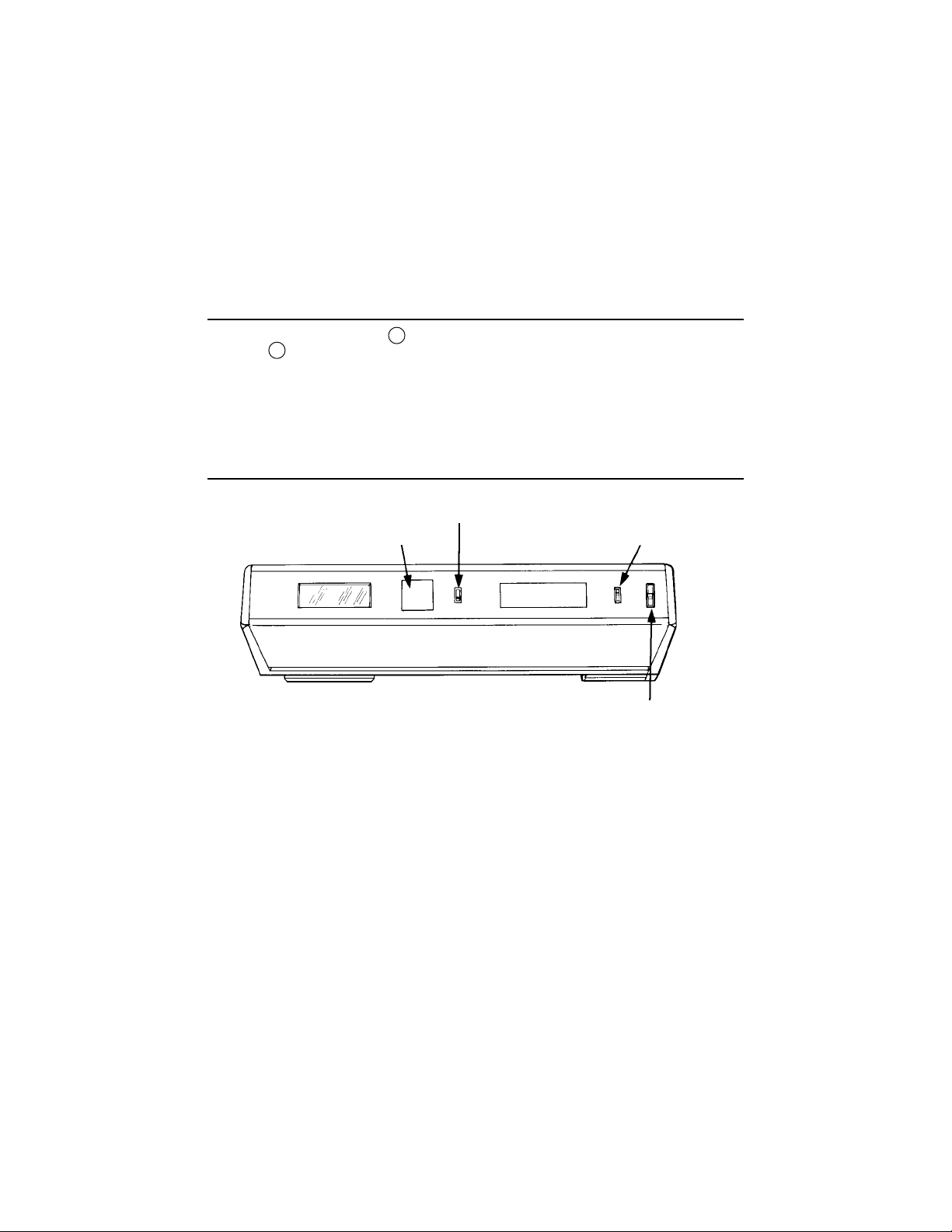
Digital Readout . . . . . . . . . . . . . . . . . 3-digit LCD display, with “Battery” icon
Traverse Length (Selectable). . . . . . See table on page 9.
Evaluation Length (Selectable) . . . . See table on page 9.
Traverse Speed . . . . . . . . . . . . . . . . . .2"/5,08mm per second
Cutoff . . . . . . . . . . . . . . . . . . . . . . . . . .030"/0,8mm; 2 RC filter
Probe Type . . . . . . . . . . . . . . . . . . . . . Piezoelectric
Maximum Stylus Force
(within displacement range) . . . . . . . 1500mgf/15.0mN
Power . . . . . . . . . . . . . . . . . . . . . . . . . 9-volt consumer-type alkaline battery
Battery Capacity . . . . . . . . . . . . . . . . Approx. 2500 measurements, depending
on frequency/degree of usage
Operating Temperature . . . . . . . . . . 50° to 113°F/10° to 45°C
Storage Temperature . . . . . . . . . . . . –
4° to 149°F/-20° to 65°C
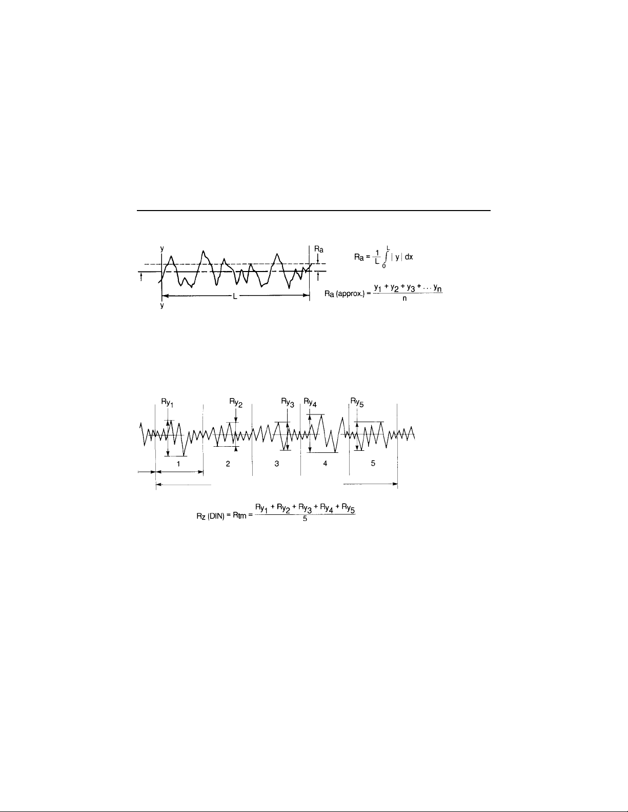
Note: Rmax and Rzper DIN 4768
Specifications
ModelsModels
ModelsModels
Models
Pocket Surf
Kit Model No.
EGH-1019 Probe and PMD-90101 EMD-1500-311
Certified Reference Specimen
EGH-1019 Probe and EMD-90010 EMD-1500-312
Precision Reference Specimen
EGH-1026 Probe and PMD-90101 EMD-1 500-321
Certified Reference Specimen
EGH-1026 Probe and EMD-90010 EMD-1500-322
Precision Reference Specimen

4
PocketSurf Measurement Parameters
RaRoughness Average—the arithmetic average height of roughness
irregularities measured from a mean line within the evaluation length (L).
Rmax Maximum Roughness Depth (per DIN) — the largest of the 5 maximum
peak-to-valley roughness depths in 5 successive sampling lengths. In
the illustration below, Rmax (DIN) = Ry 4.
RzMean Roughness Depth (per DIN) — also known as Rtm — the mean
of 5 maximum peak-to-valley roughness depths in 5 successive
sampling lengths.
Note: To fully meet the requirements of DIN 4768 for Rmax and Rz, probes having a stylus radius of
.0002"/5µm are available for use with Pocket Surf models.
MEAN
LINE
EVALUATION LENGTH (5 CUTOFFS)

5
RyMaximum Roughness Depth — For the Evaluation Length equalling
one cutoff, it is the vertical distance between the highest peak and the
deepest valley within the sampling length. For the Evaluation Length
equalling 3 cutoffs, it is the largest of the 3 maximum peak-to-valley
roughness depths in 3 successive sampling lengths.
PocketSurf Measurement Parameters (continued)

6
Pocket Surf Features
1Digital Display
2 “Start” Button
3Parameter Selection
Switch
4Output Connector
5Battery Compartment Cover
62 “V” Feet (on bottom of unit)
7Probe Holding Block
8Probe
9Protective Cover
10
Inch/Metric Switch
11
Traverse Length Switch

7
1. Remove Protective Cover 9 from Pocket Surf base and slide Battery Compartment
Cover 5 off end of Pocket Surf unit.
2. Install/replace battery and replace Battery Compartment Cover.
3. Press and release “Start” button to check battery condition (see next section).
Duracell #MN/1604 and Eveready®Energizer®#522 or other equivalent 9-volt alkaline batteries are suitable
replacements. Avoid non-alkaline or rechargeable batteries because these types do not have sufficient
power.
Pocket Surf Controls and Digital Display
BaBa
BaBa
Battertter
ttertter
ttery Installay Installa
y Installay Installa
y Installation/Rtion/R
tion/Rtion/R
tion/Ree
ee
eplacement (Alkaline onlplacement (Alkaline onl
placement (Alkaline onlplacement (Alkaline onl
placement (Alkaline onlyy
yy
y)
1. Set Inch/Metric Switch for inch (
µ
") or metric (
µ
m).
Set Traverse Length Switch for 1, 3 or 5. Refer to Traverse Length section
for details.
Set Parameter Switch to desired parameter -- Ra, Rmax, or Rz. If the Traverse
Length Switch is set to positions 1 or 3, the Rmax selection will actually calculate
Ry. Also, the Rzselection will not be calculated for positions 1 or 3, since a full 5
cutoffs are required per DIN for both Rmax and Rz.
Parameter Selection Switch
Inch/Metric Switch
Traverse Length Switch
“Start” Button

8
In addition to displaying the measured roughness value, the digital readout also
signals other conditions:
2. Immediately after pressing and releasing the
“Start” button, the readout should display the
“Battery” icon and “all 8’s” (full display), indicating
satisfactory battery condition for normal operation.
3. A “low” (weak) battery is indicated by only the
“Battery” icon being displayed on the LCD readout
— no other characters displayed. A dead battery
(or none installed) results in no display at all. In either
instance, remove and replace the battery as directed
in Battery Installation/Replacement section on page 7.
4. When taking a measurement, an
“-H-” or an “-L-” may appear,
indicating that the measured value
is out of range, either too high or too
low. Refer to Specifications section on
page 3 for parameter measuring ranges.
5. If the display “blinks” when a measurement is made, it indicates that the
displayed value has been contaminated by three or more off-scale peaks or
valleys during the measurement. For example, the probe may have traversed
over a scratch or other random irregularity on the surface. Measure again,
with the probe positioned at a different place on the surface.
6. If a malfunction or other error occurs during operation, the readout
will display an error code: “E1”, “E2”, “E3”, “E4” or “E5L”. Refer to
Maintenance & Troubleshooting section on page 24 for details.
Pocket Surf Controls and Digital Display (continued)

9
There are three traverse lengths available. For measuring short surfaces such
as o-ring grooves, short lands and shoulders use Switch Positions 1 or 3.
Nominal Number of Cutoffs/
Traverse Length Evaluation Length Switch Position
.075"/2,0mm .030"/0,8mm 1
.135"/3,5mm .090"/2,4mm 3
.195"/5,0mm .150"/4,0mm 5
Cutoff equals .030"/0,8mm.
Traverse Length
Gage Operation
The PocketSurf gage will operate in any one of four different probe positions (see
illustration on next page). Selection of the proper probe position depends on the
application.
When changing probe positions, gently grasp the probe by its body; never handle the
probe by its skid and stylus end.
Prior to operating the gage, its calibration should be checked. Refer to the
Calibration section for details.
Important: During the measuring cycle, the probe stylus and skid should be in
contact with a surface, and the setup should be properly aligned (as outlined in the
following sections). Otherwise, any readings obtained are not valid and are not to be
used for measurement or gage performance evaluation purposes.

10
The Pocket Surf gage can be hand held or placed on a surface in any attitude;
it will operate in virtually any position — horizontally, vertically, at any angle in
between, even upside-down. In the “Closed” probe position, the gage can
measure flat surfaces or cylindrical surfaces (O.D.’s) down to
¼"/6,35mm in diameter. However, the workpiece or surface to
be measured must be at least 3½"/89mm long so that
it will span the two “V’s” on the bottom of the
Pocket Surf unit and rest securely
against them.
“Closed” Position“Closed” Position
“Closed” Position
For workpieces or surfaces less than 3½"/89mm long (too
short to span the “V’s”), use of EAS-2584 Bottom Plate (an
optional accessory) is recommended.
“Closed” Position

11
To use the gage in the other probe positions — 90°, 180° or 270°, the PocketSurf
unit and probe must be carefully aligned to the workpiece surface to be measured.
The base of the PocketSurf unit must be at approximately the same elevation
(within ±.100"/±2,5mm) as the surface being measured, and the axis of probe
traverse must be parallel to the surface being measured.
With the probe positioned on the workpiece surface to be measured, carefully
adjust the gage and workpiece setup so that the black, scribed Reference Line on
the Probe Mounting Block is parallel to the bottom of the PocketSurf housing and
parallel to the work surface. This ensures that the probe skid and stylus are flush on
the surface, even though (except for the Small Bore Probes) the probe body will be at
an angle to the surface.
Other Probe PositionsOther Probe Positions
Other Probe Positions
Parallel Reference LineReference Line
Within ±.100"/±2.5mm

12
180° “Extended”180° “Extended”
180° “Extended” 90° and 270° Positions
In the 180° “Extended” position, the
PocketSurf gage can measure flat
Surfaces, large cylindrical or O.D.
surfaces and inside diameters.
Because there is some leeway
permitted in the elevation between
the base of the Pocket Surf unit and
the surface to be measured, the gage
can be used to measure surfaces
that are raised slightly above or recessed
slightly below (within ±.100”/±2.5mm)
adjacent surface(s).
Be sure the two “V’s” on the bottom of
the PocketSurf unit sit firmly on the
adjacent workpiece surface.
Inside diameters larger than
1.1"/28,0mm may be measured up to
a depth (in-reach) of 2.0"/50mm using
a General Purpose Probe. For smaller
inside diameters down to 1/8"/3,2mm an
optional Small Bore Probe is required.
For most I.D. measurements, the Pocket
Surf unit cannot be hand held; it must be
mounted on a stand such as the optional
EAS-2426 Universal Stand or EAS-2496
Height Stand. Refer to Optional
Accessories section for addtional
information.
Both the 90° and 270° positions
can be used, in conjunction with a
suitable stand or fixture for holding the
PocketSurf unit, to measure surfaces
(such as crankshaft pins and journals)
that cannot be accessed with the
probe in its “Closed” or 180°
“Extended” positions.
The 90° probe position is also used
for measuring small workpieces with
the EAS-2421 Vee Fixture. Refer to the
Vee Fixture section on page 17 for
specific instructions.

13
The Pocket Surf gage is calibrated using
the Reference Specimen and the
EPL-1681 Riser Plate supplied with the
PocketSurf Kit.
Set the Parameter Selection Switch to
“Ra”. The other two parameters, Rmax
and Rzwill automatically be calibrated
when Rais calibrated.
Set the Traverse Length Switch to
position 5 because a full 5 cutoffs are
required for proper calibration of the
instrument.
CalibrationCalibration
Calibration
Note: When calibrating with a General purpose
Probe, Groove Bottom Probe, the Transverse Chisel
Probe or a Small Bore Probe, the probe should be in
the 180° “Extended” position (as shown above). The
Parallel Chisel Probe must be in the 90° or 270°
position and the setup rearranged so that the probe
will traverse the Specimen in the direction of the
arrow.
1. To elevate the Pocket Surf base to
the same height as the surface of
the Reference Specimen, place the
Pocket Surf unit on the Riser Plate so
that the two “V’s” on the bottom of the
Pocket Surf Unit sit in the shallow
recesses of the Riser Plate. Align
the Reference Specimen so that the
gage probe will traverse across it in
the direction of the double-ended
arrow. Take a reading from the center
of the specimen.
Riser Plate
Reference Specimen
Calibration Control Access Plug

14
CalibrationCalibration
Calibration (continued)
If the reading is within ±4
µ
",/±0,1um
of the value stated on the label on the
bottom of the specimen*, calibration Is
within tolerance.
If the reading differs from the value
stated on the label (or on a Report
of Calibration certificate) by more
than ±4
µ
"/±0,1um, take additional
readings around the central area
of the Reference Specimen. If the
readings still differ by more than
the allowable tolerance, recalibrate
the PocketSurf unit following the
procedure below.
2. Remove the Calibration Control
Access Plug.
3. Using a jeweler’s screwdriver,
carefully adjust the Calibration
Control.
—clockwise to increase
the displayed Ravalue, or
—Counterclockwise to decrease
the displayed Ravalue.
4. After adjusting the calibration
control, re-measure the Reference
Specimen to assure that the Pocket
Surf unit is within the calibration
tolerance.
5. Replace the Calibration Control Access
Plug.
To check the condition of the probe
stylus, a “double patch” Reference
Specimen (optionally available) is
recommended. A “double patch”
Specimen can also be used for
calibration of the gage; however,
be sure to use only the 125µ
µ
µ"/3.17µ
µ
µm
section of the specimen for
calibration purposes. Be careful not to
use the other section of the “double
patch” Specimen for calibration as it
could introduce serious errors into
the gage’s roughness readings. The
20µ"/0.5 section is only to be used for
checking probe stylus condition.
*Or on the Report of Calibration certificate
which accompanies a “Certificate”
Reference Specimen.

15
General Purpose Probe
(normally furnished) — For most
surface roughness applications.
90° conical diamond stylus –
.0004"/10
µ
m radius for EGH-1019,
.0002"/5
µ
m radius for EGH-1026.†
Transverse Chisel Probe
EGH-1020-W1 (optional) — For
gaging sharp edges or small
O.D.’s where the probe moves
parallel to the axis of traverse.
90° sapphire chisel stylus,
.0004"/10
µ
m radius.
Parallel Chisel Probe
EGH-1020-W2 (optional) — For
outside diameters smaller than
¼"/6,35mm (placed in the
EAS-2421 “V” Fixture), or
measuring sharp edges
with the probe in the 90° or
270° position (perpendicular
to the axis of traverse).
90° sapphire chisel stylus,
.0004"/10
µ
m radius.
Small Bore Probe (optional) —
For measuring small bores
(min. inside diameter of 1/8"/3,2mm)
up to a depth (“in-reach”) of .80"/20,3mm.
90° conical diamond stylus –.0004"/10
µ
m
radius for EGH-1021, .0002"/5
µ
m for EGH-1027.†
PocketSurf ProbesPocketSurf Probes
PocketSurf Probes
Small Bore Probes and the Groove Bottom Probe can only be used in the 180° “Extended” position with
the Pocket Surf unit supported in a height stand or other suitable fixture; they are not intended to be used
in any other position.
† Yellow dot at connector end signifies .0002"/5µm radius.

16
Groove Bottom Probe
EGH-1028 (optional) — For
measuring the bottoms of
“O” ring grooves, recesses and
holes to depths of ¼"/6,35mm.
Also used for short lands and
shoulders. 90° conical diamond
stylus—.0004"/10
µ
m radius.
The Groove Bottom Probe can only be used in the 180° “Extended” position with the Pocket Surf unit
supported in a height stand or other suitable fixture; they are not intended to be used in any other position.
PocketSurf Probes (continued)
1. Turn the PocketSurf unit upside down and swivel the
Probe to its 90° “Extended” position.
2. Loosen the knurled Locking Collar by turning it
counterclockwise approximately 2 1/2 turns, until the
access slot is aligned with the Probe Pin slot in the
Probe Mounting Block. Grasping the probe by its body
section, carefully withdraw the Probe from its
Mounting Block and the knurled Locking Collar.
Do not grasp the probe by its skid and stylus end.
Caution: Do not remove the knurled Locking Collar
from the Probe Mounting Block; loosen it only enough
to slide the Probe out easily.
3. Reverse the procedure to install a Probe, aligning the
Pin on the bottom of the probe body with the access
slot in the Locking Collar.
Note: Make sure that the Probe is fully inserted into
the Probe Mounting Block (so that the electrical
connector is completely engaged) before tightening
the Locking Collar. Finger tighten only.
4. Check the gage’s calibration after changing Probes.
Probe Replacement

17
The EAS 2421 Vee Fixture is used for
measuring cylindrical (O.D.) parts up to
approximately 1"/25mm in diameter that
are too small to be accommodated in the
gage’s “Closed” probe position mode. The
fixture consists of two parts — a Top Plate
for holding the PocketSurf unit and a
Bottom Plate with a Vee for holding the
workpiece.
With the Vee Fixture, the probe is used in
its 90° position. Either a General Purpose
Probe or an optional Parallel Chisel Probe
(which is recommended for cylindrical
parts less than ¼"/6,35mm in diameter)
can be used.
EAS-2421 VEE Fixture
1. Mount the Pocket Surf unit,
with the probe in its 90°
position, to the fixture’s
Top Plate using the captive
screw in the Top Plate.
The screw mates with the
tapped hole in the bottom
of PocketSurf housing.
2. Place the cylindrical
workpiece to be measured
across the Vee on the
Bottom Plate.
3. Position the Top Plate,
with the Pocket Surf unit
attached to it, on the
fixture’s Bottom Plate so
that the Top Plate’s two
legs rest in the recesses
in the Bottom Plate and the
probe stylus and skid rest
on the top of the workpiece.
4. Use the fixture’s
Adjustment Screw to raise
or lower the Top Plate so
that the Reference Line on
the Probe Mounting Block
is parallel to the bottom of
the Pocket Surf housing
(as outlined in the Gage
Operation section).
When correctly adjusted,
tighten the knurled Lock Nut
on the Adjustment Screw to
secure the setup.
Parallel
Top Plate
Lock Nut
Bottom Plate
Adjustment
Screw

18
For accurate measurement with the
Vee Fixture, the axis of the Vee must
be aligned parallel to the axis of probe
traverse and at the proper distance
from the PocketSurf unit so that the
probe skid and stylus travel precisely
along the top (“crown” or “high spot”)
of the workpiece.
The Vee Fixture was set, at the factory,
for correct parallelism and distance
to accommodate its normal range of
cylindrical workpiece sizes from
1/8"/13,2mm up to approximately
1"/25mm in diameter. If, for some
reason, the factory setting has been
disturbed, or another workpiece fixture
is installed in place of the normally
furnished Vee, its alignment must be
reset. To adjust the Vee (or other fixture),
use the following procedure.
Vee Fixture Alignment
1. Slightly loosen the two screws that
secure the Vee to the fixture’s Bottom
Plate just enough so that the Vee can
be repositioned with a little effort.
2. Place the 1/8"/3,2mm diameter Setting
Pin, PS-145, in the Vee and proceed to
measure it like a regular workpiece
(steps 3 and 4 from previous page).
Closely observe the path of the probe
skid and stylus on the Setting Pin
during the traverse.
Parallel
Setting Pin
Screws(2)
Axis of
Probe Traverse
Axis of
"V"

19
3. Carefully adjust the position of
the Vee so that the probe skid
and stylus travel precisely along
the top (“crown” or “high spot”)
of the Setting Pin throughout the
entire traverse (measurement
stroke). Make several passes to
ensure that the Vee is properly
adjusted, and that the probe skid
and stylus do not wander off the
top of the Setting Pin during the
traverse.
4. Once the Vee is properly
adjusted, remove the Top Plate
(with the PocketSurf unit on it) from
the Bottom Plate, and remove the
Setting Pin from the Vee. Securely
tighten the two screws in the
bottom of the Vee. Be very careful
not to disturb the position of the
Vee in performing this step.
Vee Fixture Alignment (continued)
5. Place the Setting Pin back in the
Vee and place the Top Plate (with the
Pocket Surf unit) back on the Bottom
Plate, with the probe skid and stylus
resting on the top of the Setting Pin.
Make two or three more traverses to
ensure that proper alignment of the
Vee was maintained after it was
secured.
Alternate Vee’s or other fixturing,
fabricated by the user to accommodate
specific workpieces, can be substituted
for the normally furnished Vee.

20
Optional Accessories
EAS 2426 Universal Stand
The EAS 2426 Universal Stand
is a heavy duty, fully adjustable,
multiposition comparator stand for
staging the PocketSurf unit in any
position relative to the workpiece
surface to be measured. The stand
will accommodate workpieces
ranging in height from flush with
the stand’s work surface up to 8.4"/
215mm high, and can be used with
or without additional workpiece
fixturing.
The probe can be in its 90°,180°
“Extended” or 270° positions. The stand’s
360° Column Clamp and Bracket can be
positioned anywhere vertically and radially
on the column, permitting the stand to be
used as a height stand on a surface plate
or other suitable work surface to measure
workpieces positioned adjacent to it.
1Column Clamp —
to adjust height
(Elevation) and radial
position around
column (thru 360°)
2Tilt — to adjust
PocketSurf bracket
in plane parallel to
column (thru 360°)
3Tilt — to adjust
PocketSurf bracket in
plane perpendicular
to column (thru 90°)
A typical application using the Universal Stand. Note that the bracket with the PocketSurf unit is tilted, using
adjustment 2 , to align with the tapered workpiece surface being measured.
This manual suits for next models
3
Table of contents