Maico MV25 Service manual

1
Beiblatt für Montage- und
Betriebsanleitungen
Insert for mounting and
operating instructions
Supplément aux instructions de
montage et mode d’emploi
Motorvollschutzschalter MV 25
1. Verwendete Warnsymbole
GEFAHR
Lebensgefahr !
Eine Nichtbeachtung kann
zum Tod oder zu schweren
Körperverletzungen führen.
VORSICHT
Verletzungsgefahr ! Sachschä-
den ! Eine Nichtbeachtung kann
zu leichten bis mittleren Körper-
verletzungen oder Sachschäden
führen.
2. Produktinformationen
●Gerät mit Hauptschütz und Steuersicherung.
●Bei Überschreitung der zulässigen Tem-
peratur in der Motorwicklung des Ventilators
wird der Steuerstromkreis unterbrochen
(Anschluss „TK“). Das Hauptschütz fällt ab
und trennt den Motor vom Netz.
VORSICHT
Verletzungsgefahr durch
automatisch anlaufenden
Ventilatormotor nach einem
Netzausfall !
Am Ventilator nicht in den
Bereich des Flügelrades
greifen und keine Gegen-
stände in den Bereich des
Flügelrades stecken !
Abmessungen
●MV 25 (B x H x T): 75 x 140 x 95 mm
Spannungsversorgung
●Bemessungsspannung: 400 V
●Maximalbelastung: 25 A
●Netzfrequenz: 50 Hz oder 60 Hz
Schutzart
●MV 25: IP 54
3. Umgebungsbedingungen und
Grenzen für Betrieb
●Zulässige Umgebungstemperatur: 40 °C
4. Grundlegende
Sicherheitshinweise
Allgemeine Sicherheitshinweise
●Anleitung aufbewahren.
●Montage, elektrischer Anschluss und
Reparaturen nur durch Elektrofachkräfte
zulässig.
●Motorvollschutzschalter nur an einer fest
verlegten elektrischen Installation anschlie-
ßen. Leitungstyp und -querschnitt gemäß
DIN VDE 0298-4 auswählen. Vorrichtung
zur Trennung vom Netz mit mindestens
3,0 mm Kontaktöffnung je Pol erforderlich.
●Gerät nur mit auf Typenschild angegebener
Spannung und Frequenz betreiben.
●Veränderungen und Umbauten am Gerät
sind nicht zulässig und entbinden MAICO
von jeglicher Gewährleistung und Haftung.
●Gerät nur mit Gehäusedeckel betreiben.
Bestimmungsgemäße Verwendung
●Motorvollschutzschalter für Ventilatoren mit
ausgeführten Thermokontakten.
●Zum Schutz von Drehstrommotoren.
●Zur Aufputzmontage.
Nicht zulässiger Betrieb
Gerät auf keinen Fall einsetzen:
●In der Nähe von brennbaren Materialien,
Flüssigkeiten oder Gasen.
●In explosionsfähiger Atmosphäre.
www.maico-ventilatoren.com

2
5. Technische Daten
Siehe Typenschild.
6. Montage, Elektrischer Anschluss
GEFAHR
Lebensgefahr durch
Stromschlag !
Netzsicherung ausschalten !
Beide Schrauben des Gehäusedeckels
entfernen, Gehäusedeckel abnehmen.
Entsprechend der Anzahl der Leitungen
Leitungsdurchbrüche an den Sollbruch-
stellen im Gehäuseunterteil ausbrechen
und Tüllen einsetzen.
Gehäuseunterteil an der Wand befestigen
– geeignetes Befestigungsmaterial
bauseitig bereitstellen.
Anschlussleitungen durch die Tüllen in das
Gehäuse führen.
VORSICHT
Kurzschlussgefahr und
Gerätebeschädigung durch
eindringendes Wasser oder
Feuchtigkeit !
Tüllen so einsetzen, dass diese
die Leitungen dicht umschließen.
Motorvollschutzschalter gemäß Schaltbild
verdrahten.
VORSICHT
Beschädigung der Thermo-
kontakte bei falschem
Anschluss !
Thermokontakt nur an die mit
„TK“ bezeichneten Klemmen
anschließen.
Gehäusedeckel aufsetzen und mit beiden
Schrauben verschrauben.
Netzsicherung einschalten.
Funktionstest durchführen.
7. Instandhaltung
●Das Gerät ist wartungsfrei.
8. Störungsbehebung
●Nach dem Abkühlen der Motorwicklung
verhindert eine Wiedereinschaltsperre das
selbsttätige Einschalten des Motors.
●Bei vorzeitigem Einschalten (innerhalb von
1 min.) erfolgt erneute Auslösung.
Zum Wiedereinschalten Taste „0“ und
danach Taste „1“ drücken.
9. Schaltbild
D

3
MV 25 Motor protection switch
1. Warning symbols used
DANGER
Danger to life !
If ignored, this may lead to death
or severe personal injury.
CAUTION
Danger of injury ! Material
damage ! If ignored, this may
lead to minor or more serious
personal injury or material
damage.
2. Product information
●Device with main contactor and control fuse.
●The control circuit is interrupted if the
permitted temperature in the motor winding
is exceeded (“TK” connection). The main
contactor drops out and separates the
motor from the power.
CAUTION
Danger of injury caused
through automatic startup of
fan motor, following a power
cut !
Do not reach into or insert any
objects into the area of the
impeller.
Dimensions
●MV 25 (W x H x D): 75 x 140 x 95 mm
Power supply
●Rated voltage: 400 V
●Maximum load: 25 A
●Mains frequency: 50 Hz or 60 Hz
Degree of protection
●MV 25: IP 54
3. Environmental conditions and
operational limits
●Permitted ambient temperature: 40 °C
4. Basic safety instructions
General notes regarding safety
●Retain instructions.
●Installation, electrical connections and
repairs by trained personnel only.
●Connect motor protection switch to fixed
electrical installation. Select cable type and
cross-section to conform with DIN VDE
0298-4. Circuit breaker with contact
openings of at least 3.0 mm at each pole
required.
●Operate device at voltage and frequency
stated on rating plate only.
●Modifications and changes to the device
are not permitted and if carried out, they
release MAICO from any and all guarantee
commitments or liability.
●Only operate device with cover.
Intended use
●Motor protection switch for fans with fitted
thermal contacts.
●To protect three-phase AC motors.
●For surface installation.
Non-permissible usage
The device should not be used:
●In the vicinity of combustible materials,
fluids or gases.In explosive areas.
5. Technical Data
See the rating plate.
GB

4
6. Installation, Electrical connection
DANGER
Danger to life from electrical
shock!
Switch power off. !
Unscrew both screws from the housing
cover and remove the cover.
Make holes in the breakout points in the
lower part of the housing, corresponding to
the number of cables and insert grommets.
Fix the lower part of the housing to the wall
using fixing material provided by the
customer.
Feed the connection cables through the
grommets.
CAUTION
Danger of short-circuit and
damage to the device, caused
by the penetration of water or
damp !
Position the grommets such
that they fit tightly round the
cables.
Wire up the motor protection switch
according to the wiring diagram.
CAUTION
A wrong connection will
damage the thermal contact !
Only contact the thermal
contact to the connector
labelled “TK”.
Replace the housing cover and screw it
back down using both screws.
Switch the main fuse on.
Carry out a function test.
7. Maintenance
●The device is maintenance-free.
8. Fault rectification
●An auto-restart block prevents the motor
switching itself back on after the motor
winding has cooled down.
●If switched back on too soon (within 1
minute), the protection switch is re-
triggered.
Press button “0” and then button “1” to
switch back on.
9. Wiring diagram
GB

5
Disjoncteur-protecteur
intégral MV 25
1. Symboles d'avertissement
utilisés
DANGER
Danger de mort !
Le non respect peut entraîner
des blessures corporelles
graves, voire la mort.
ATTENTION
Risque de blessure ! Dommages
matériels ! Le non respect peut
entraîner des blessures
corporelles légères à
moyennement graves ou des
dommages matériels.
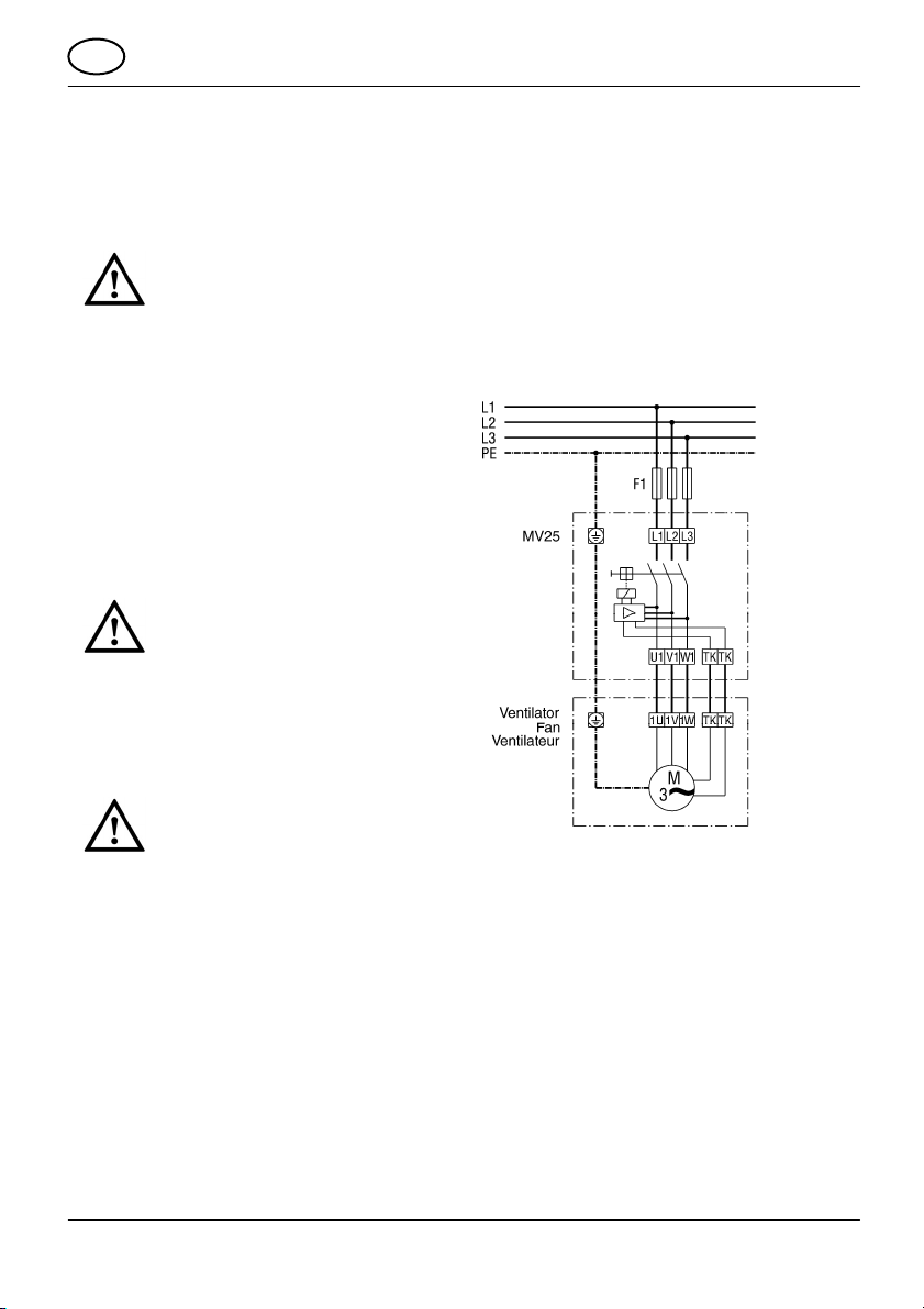
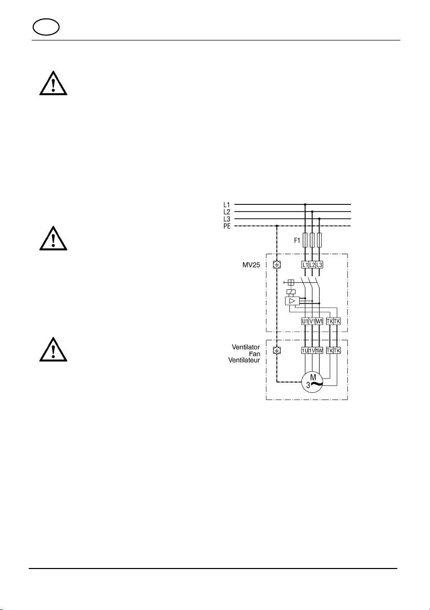
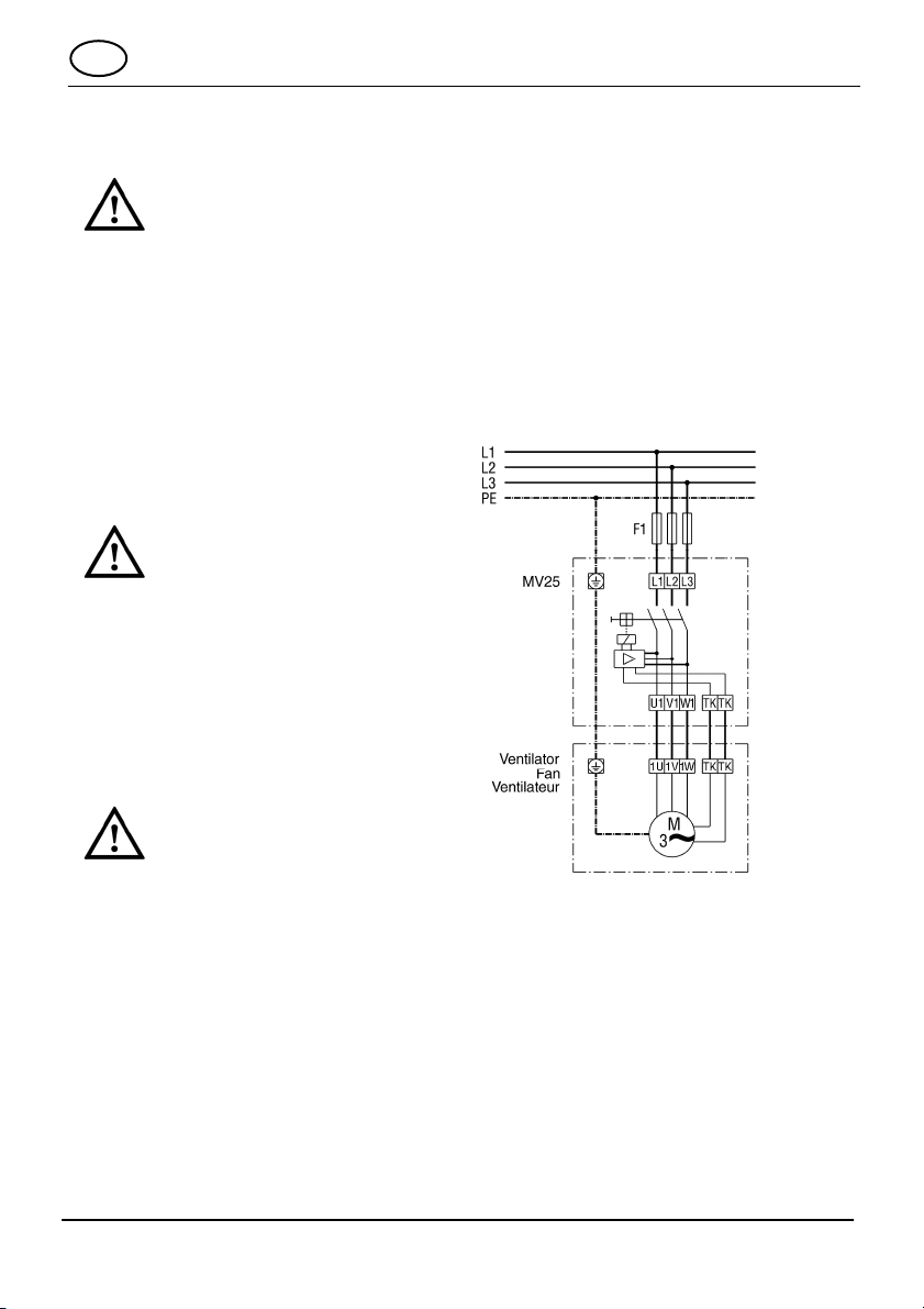
2. Informations produit
●Appareil muni d’un contacteur général et
d’un fusible de commande.
●En cas de dépassement de la température
admissible dans la bobine de moteur du
ventilateur, le circuit de courant de
commande est interrompu (raccord
« TK »). Le contacteur général se coupe et
déconnecte le moteur du secteur.
ATTENTION
Risque de blessure par le
moteur du ventilateur à
démarrage automatique après
une coupure secteur !
Ne pas toucher à la zone de
l’hélice située au niveau du
ventilateur et ne pas en
approcher d’objets !
Dimensions
●MV 25 (L x H x P) : 75 x 140 x 95 mm
Alimentation électrique
●Tension de service 400 V
●Charge maximale : 25 A
●Fréquence du secteur: 50 Hz ou 60 Hz
Type de protection
●MV25: IP54
3. Conditions environnementales
et limites d'utilisation
●Température ambiante admissible: 40 °C
4. Consignes de sécurité
fondamentales
Consignes de sécurité générales
●Conserver le manuel.
●Montage, branchement électrique et
réparations exclusivement réservés à des
électriciens qualifiés !
●Le disjoncteur-protecteur intégral doit
impérativement être raccordé à une
installation électrique permanente. Le type
et la section de la conduite doivent être
choisis conformément à la norme DIN VDE
0298-4. Dispositif de déconnexion du
secteur avec au moins 3,0 mm d’ouverture
de contact par pôle.
●Utiliser l'appareil exclusivement à la
tension et à la fréquence indiquées sur la
plaque signalétique.
●Des modifications ou transformations de
l’appareil ne sont pas autorisées et
dégagent MAICO de toute responsabilité.
●L’appareil doit toujours fonctionner muni de
son couvercle de boîtier.
Utilisation conforme
●Disjoncteur-protecteur intégral pour.
ventilateurs avec thermocontacts intégrés.
●Pour la protection des moteurs à courant
triphasé.
●Pour montage apparent.
Fonctionnement non autorisé
Ne jamais monter l’appareil:
●À proximité de matières, liquides ou gaz
inflammables.
●Dans une atmosphère explosive.
5. Caractéristiques techniques
Voir plaque signalétique.
F

6
6. Montage, Branchement
électrique
DANGER
Risque d’électrocution !
Mettre le fusible secteur hors
service !
Desserrer les deux vis du couvercle du
boîtier, retirer ce dernier.
Selon le nombre de conduites, briser les
percées de conduite au niveau des points
destinés à la rupture situés sur la paroi
inférieure du boîtier et fixer les manchons.
Fixer la partie inférieure du boîtier sur le
mur. Le client doit fournir le matériel de
fixation approprié.
Amener les conduites de raccordement
dans le boîtier via les manchons.
ATTENTION
Risque de court-circuit et
d’endommagement de
l’appareil en cas de
pénétration d’eau ou
d’humidité !
Fixer les manchons de sorte
qu’ils enserrent fermement les
conduites.
Câbler le disjoncteur-protecteur intégral
conformément au schéma de
branchement.
ATTENTION
Endommagement des thermo-
contacts en cas de branche-
ment électrique incorrect !
Ne raccorder le thermocontact
que sur les bornes portant la
désignation « TK ».
Poser le couvercle du boîtier et le fixer à
l’aide des deux vis.
Enclencher le fusible secteur.
Effectuer un test de fonctionnement.
7. Maintenace
●L'appareil ne nécessite aucun entretien.
8. Dépannage
●Après le refroidissement de la bobine de
moteur, le verrouillage au réenclenchement
prévient le redémarrage automatique du
moteur.
●En cas de remise en marche prématurée
(dans les 60 secondes), un nouveau
déclenchement a lieu.
Appuyer sur les touches « 0 » puis « 1 »
pour procéder à la remise en service.
9. Schéma de branchement
F

7

8
Maico Elektroapparate-Fabrik GmbH • Steinbeisstr. 20 • 78056 Villingen-Schwenningen •
DSW_1103._400.02285.0018 s11_E03.
Other manuals for MV25
1
This manual suits for next models
1
Table of contents
Languages: