Maipu MP1900X Series User manual

MP1900X Series Router
Installation Manual
V 1 . 0


Copyright Statement
Copyright2019 Maipu Communication Technologies Co., Ltd. All rights reserved.
Without the written approval of the Company, no company or individual is allowed to
extract, reproduce, translate or propagate this Manual, in whole or in part, in whatsoever
manner.
and are the trademarks of Maipu Communication Technologies Co.,
Ltd. All other trademarks, product marks and trade names referenced herein are owned
by their owners respectively.
This Manual may be subject to changes on account of product upgrade or other causes.
Maipu reserves the right to revise this Manual without any notice. Subject to the laws and
regulations, Maipu Communication Technologies Co., Ltd. shall, under no circumstance,
be responsible for any accident, negligence, breach of contract, defamation and
infringement of copyright or intellectual property right incurred by using the related
content of this Product Manual or this website, assume any liabilities for damage with
respect to any special, incidental, indirect or secondary losses and any losses on profit,
data, business reputation or expected economy so caused or bear any legal liabilities so
arisen.
Safety Statement
Important! Please read the product safety and compatibility information before energizing
and enabling the product.
Environmental Statement
This product complies with the design requirements in terms of environmental protection
and shall be stored, used and disposed in accordance with the related national laws and
regulations.

Preface
MP1900X Series Router Installation Manual
ii copyright2019 Maipu, all rights reserved
Preface
Manual Introduction
This manual introduces the appearance, hardware, and installation preparation and
method of the MP1900X series router, as well as its basic use and daily maintenance
in terms of energization & operation, troubleshooting and equipment maintenance.
Product Version
This manual is applicable to the product versions as below.
Product name Product Version
MP1900X series router
MP1900X-12-AC(V1)
MP1900X-22-AC(V1)
Target Users
The major target users of this Manual are:
Hardware Installation Engineer
Debugging Engineer
Site Maintenance Engineer
System Maintenance Engineer
Convention
Convention of screen output formats
Format Description
Screen print Screen output
Keywords of Screen print Key information of screen output (red part)

MP1900X Series Router Installation Manual Preface
copyright2019 Maipu, all rights reserved iii
Convention of icons and signs
Format Description
Note: Supplement to or emphasis on the aforesaid.
Caution:
Matters that need attention while installing or operating the
equipment, which are important for proper installation and
operation.
Warning:
Operations prohibited or required to follow the specified steps;
otherwise, personal injuries or equipment damages are possible.
Convention of command formats
Format Description
Bold Keywords of command line
Italic Parameters of command line
Brace “{ }” Options in the brace are compulsory.
Bracket “[ ]” Options in the bracket are optional.
Angle bracket “<>” Information in the angle bracket is not displayed.
Square bracket “【】”
Contents in the square bracket need attention.
Upright slash “|” A sign to separate the options, with the same meaning as “or”.
Slash “/” A sign to separate the options, indicating a multi-choice
operation.
For the purpose of this manual, the icons have the definitions as below:
Icons Description
This icon and its related description generally refer to the
switch.
Product Details

Preface
MP1900X Series Router Installation Manual
iv copyright2019 Maipu, all rights reserved
The manual matching with the product is as follows:
Manual Description
MP1900X Series Router
Configuration Manual
Detailed introduction to the methods and steps of
configuring the equipment software functions, with the
typical cases made available for reference.
Technical Support
Technical support hotline: 400-65710935 & 400-886-8669
Email (feedback): support@maipu.com
Revision History
The Revision History is the summary of all manual updates. The latest version includes
all previous updates.
Version Revision date Description
V1.0 2018-5-25 First issue

MP1900X Series Router Installation Manual Preface
copyright2019 Maipu, all rights reserved v
Contents
PREFACE ················································································································· II
1 ROUTER INTRODUCTION ··················································································· 1-1
1.1 MP1900X-12-AC APPEARANCE AND HARDWARE STRUCTURE ········································· 1-1
1.2 MP1900X-22-AC APPEARANCE AND HARDWARE STRUCTURE ········································· 1-2
1.3 PANEL SPECIFICATIONS OF MP1900X SERIES ROUTER ·················································· 1-3
1.4 AIR PASSAGE OF MP1900X SERIES ROUTER ······························································· 1-4
1.5 POWER MODULE OF MP1900X SERIES ROUTER ·························································· 1-5
2 INSTALLATION PREPARATIONS ·········································································· 2-1
2.1 CHECK ROUTER RUNNING ENVIRONMENT ································································· 2-1
2.2 SAFETY PRECAUTIONS ························································································· 2-1
2.2.1 GENERAL SAFETY ······························································································ 2-1
2.2.2 ELECTRICAL SAFETY ·························································································· 2-2
2.2.3 STATIC SAFETY ································································································· 2-2
2.2.4 LASER SAFETY·································································································· 2-3
2.3 INSTALLATION TOOLS, INSTRUMENTS, AND EQUIPMENT ················································· 2-3
2.4 OPEN-PACKAGE AND INSPECTION ············································································ 2-4
3 ROUTER INSTALLATION ···················································································· 3-5
3.1 INSTALL ROUTER ································································································ 3-5
3.1.1 INSTALL ROUTER TO WORKBENCH ··········································································· 3-5
3.1.2 INSTALL ROUTER TO CABINET ················································································ 3-5
3.2 GROUND THE ROUTER ·························································································· 3-9
3.3 (OPTIONAL) INSTALL SPD ···················································································· 3-10
3.3.1 INSTALL AC POWER SPD ····················································································· 3-10
3.3.2 (OPTIONAL) INSTALL PORT LIGHTNING PROTECTOR ····················································· 3-11
3.4 CONNECT POWER CABLE ····················································································· 3-13
3.4.1 INSTALLATION PREPARATIONS ··············································································· 3-13
3.4.2 CONNECT AC POWER CABLE ················································································ 3-13
3.5 CHECK AFTER INSTALLATION ················································································ 3-13
4 POWER ON AND RUN ROUTER ············································································ 4-1

Preface
MP1900X Series Router Installation Manual
vi copyright2019 Maipu, all rights reserved
4.1 LOG INTO ROUTER ······························································································ 4-1
4.1.1 CONNECT CONSOLE CABLE ··················································································· 4-1
4.1.2 SET PC HYPERTERMINAL PARAMETERS ····································································· 4-2
4.1.3 POWER ON AND START ························································································· 4-6
4.1.4 CHECK AFTER POWER ON ····················································································· 4-7
4.2 ACCESS NETWORK ······························································································ 4-8
4.2.1 ACCESS NETWORK VIA ETHERNET TWISTED PAIR ························································· 4-8
4.2.2 ACCESS NETWORK VIA FIBER ················································································ 4-8
4.3 HARDWARE MANAGEMENT ··················································································· 4-12
4.3.1 VIEW SOFTWARE AND HARDWARE VERSION INFORMATION OF ROUTER ······························· 4-12
4.3.2 VIEW POWER STATUS INFORMATION ······································································· 4-13
4.3.3 VIEW SYSTEM ENVIRONMENT TEMPERATURE INFORMATION ··········································· 4-14
4.3.4 VIEW FAN STATUS INFORMATION ··········································································· 4-14
4.3.5 VIEW SWAPPABLE OPTICAL MODULE INFORMATION ····················································· 4-15
5 TROUBLESHOOTING ························································································· 5-1
5.1 TROUBLESHOOTING OF CONFIGURATION SYSTEM ························································ 5-1
5.1.1 TROUBLESHOOTING ABOUT NO DISPLAY ON TERMINAL ·················································· 5-1
5.1.2 TROUBLESHOOTING ABOUT MESSY CODE ON TERMINAL ················································· 5-1
5.2 TROUBLESHOOTING ABOUT FAN ·············································································· 5-2
5.3 TROUBLESHOOTING ABOUT POWER ········································································· 5-2
5.4 GET TECHNICAL SUPPORT ····················································································· 5-3
6 ROUTER MAINTENANCE ···················································································· 6-1
6.1 CHANGE INTERFACE DAUGHTER CARD ····································································· 6-1
6.2 CHANGE SWAPPABLE OPTICAL MODULE ··································································· 6-3
6.3 DE-DUST THE ROUTER ·························································································· 6-5
6.3.1 DE-DUST THE FAN ······························································································ 6-5
6.3.2 DE-DUST THE INTERFACE DAUGHTER CARD································································ 6-6
6.3.3 DE-DUST OPTICAL INTERFACE AND PIGTAIL CONNECTOR ················································ 6-7
APPENDIX ············································································································· A-1
A Entire Router and Common Module Specifications ··························································· A-1

MP1900X Series Router Installation Manual Preface
copyright2019 Maipu, all rights reserved vii
A1 Power Consumption/Dimension/Weight······································································· A-1
B Specifications of General Interfaces ············································································· B-1
B1 10Base-T/100Base-TX/1000Base-T-RJ45 Electrical Interface Attributes ································· B-1
B2 1000Base-X-SFP Optical Interface Attributes ································································ B-2
B3 USB Interface Attributes ························································································· B-2
B4 CONSOLE Port Attributes ······················································································ B-3
B5 Micro USB Interface Attributes ················································································· B-3
C Router Running Environment Requirement ···································································· C-3
C1 Environment Requirement ······················································································· C-3
C1.1 Temperature Requirement ····················································································· C-3
C1.2 Humidity Requirement ························································································ C-4
C1.3 Cleanliness Requirements ····················································································· C-5
C1.4 Anti-Interference Requirement ··············································································· C-6
C1.5 Grounding Requirement ······················································································· C-6
C2 Requirements for Power Supply ················································································ C-6
C2.1 AC Power Supply Requirement ·············································································· C-6
C2.2 Suggestions on fundamental AC power supply ····························································· C-7
D Router Grounding Specifications and Protection ······························································ D-1
D1 Router Grounding Specifications ··············································································· D-1
D1.1 General Grounding Specifications ··········································································· D-1
D1.2 Grounding Specifications for the Building ·································································· D-1
D1.3 Router Grounding Specifications ············································································· D-1
D1.4 Grounding Specifications for Communication Power ····················································· D-2
D1.5 Laying Specifications of Signal Cable ······································································· D-3
D1.6 Laying Specifications of Ground Wires ····································································· D-3
D2 Router Protection ································································································· D-4
D2.1 General Requirement of Lightning Protection Wires ······················································ D-4
D2.2 Installation Method of Cable Wiring ········································································· D-5
D2.3 Equipotential Connection Method ··········································································· D-7
E Cables ················································································································ E-1

Preface
MP1900X Series Router Installation Manual
viii copyright2019 Maipu, all rights reserved
E1 Console Cables ···································································································· E-1
E2 GE Ethernet Interface Cable ····················································································· E-2
F Environmental Substance Statement ··············································································· E-2

MP1900X Series Router Installation Manual Preface
copyright2019 Maipu, all rights reserved ix
Figure
FIGURE 1-1 THE FRONT APPEARANCE DIAGRAM OF MP1900X-12-AC ........................................................................ 1-1
FIGURE 1-2 THE REAR APPEARANCE DIAGRAM OF MP1900X-12-AC .......................................................................... 1-2
FIGURE 1-3 THE FRONT APPEARANCE DIAGRAM OF MP1900X-22-AC ........................................................................ 1-2
FIGURE 1-4 THE REAR APPEARANCE DIAGRAM OF MP1900X-22-AC .......................................................................... 1-3
FIGURE 2-1 USING METHOD OF ANTI-STATIC WRIST ....................................................................................................... 2-3
FIGURE 3-1 THE MINIMUM SLIDE HEIGHT ........................................................................................................................ 3-6
FIGURE 3-2 INSTALL THE FLOATING NUT ......................................................................................................................... 3-7
FIGURE 3-3 INSTALL THE ROUTER TO THE 19-INCH STANDARD CABINET ....................................................................... 3-8
FIGURE 3-4 CONNECT THE GROUND CABLE ................................................................................................................. 3-10
FIGURE 3-17 THE POWER SPD .................................................................................................................................... 3-11
FIGURE 3-18 CONNECT TO THE AC POWER CABLE ...................................................................................................... 3-13
FIGURE 4-1 CONSOLE CABLE .......................................................................................................................................... 4-2
FIGURE 4-2 CONNECT THE ROUTER AND PC VIA THE CONSOLE PORT .......................................................................... 4-2
FIGURE 4-3 “LOCATION INFORMATION” INTERFACE ...................................................................................................... 4-3
FIGURE 4-4 THE TELEPHONE AND MODEM INTERFACE ................................................................................................. 4-3
FIGURE 4-5 “CONNECTION DESCRIPTION” INTERFACE ................................................................................................... 4-4
FIGURE 4-6 “CONNECT TO” INTERFACE .......................................................................................................................... 4-4
FIGURE 4-7 “COM* PROPERTIES” INTERFACE ................................................................................................................. 4-5
FIGURE 4-8 “TEST-HYPERTERMINAL” INTERFACE .......................................................................................................... 4-5
FIGURE 4-9 “TEST PROPERTIES” INTERFACE .................................................................................................................. 4-6
FIGURE 4-10 TEST-HYPERTERMINAL INTERFACE AFTER SETTING ................................................................................. 4-6
FIGURE 4-11 APPEARANCE OF THE LC FIBER CONNECTOR ........................................................................................... 4-9
FIGURE 4-12 PULL OUT THE DUST PLUG ......................................................................................................................... 4-9
FIGURE 4-13 SFP MODULE ........................................................................................................................................... 4-10
FIGURE 4-14 INSTALL THE SFP MODULE ...................................................................................................................... 4-10
FIGURE 4-15 REMOVE THE OPTICAL DUST CAP ............................................................................................................ 4-11
FIGURE 4-16 REMOVE THE DUST CAP OF THE SFP MODULE ....................................................................................... 4-11
FIGURE 4-17 CONNECT THE OPTICAL FIBER ................................................................................................................. 4-11
FIGURE 4-18 INSTALL THE DUST CAP OF THE OPTICAL INTERFACE ............................................................................... 4-12

Preface
MP1900X Series Router Installation Manual
x copyright2019 Maipu, all rights reserved
FIGURE 6-1 LOOSEN THE CAPTIVE SCREW ..................................................................................................................... 6-1
FIGURE 6-2 UNINSTALL THE INTERFACE DAUGHTER CARD ............................................................................................. 6-2
FIGURE 6-3 INSTALL THE INTERFACE DAUGHTER CARD .................................................................................................. 6-2
FIGURE 6-4 FIX THE CAPTIVE SCREW ............................................................................................................................. 6-3
FIGURE 6-5 UNINSTALL THE SFP MODULE ..................................................................................................................... 6-3
FIGURE 6-6 INSTALL THE DUST CAP OF THE SFP MODULE ............................................................................................. 6-4
FIGURE 6-7 INSTALL THE SFP MODULE .......................................................................................................................... 6-4
FIGURE 6-8 UNINSTALL THE DUST CAP OF THE SFP MODULE ........................................................................................ 6-4
FIGURE 6-9 THE SFP CONNECTION FIBER ..................................................................................................................... 6-5

MP1900X Series Router Installation Manual Preface
copyright2019 Maipu, all rights reserved xi
Appendix Figure
APPENDIX FIGURE D-1 DIAGRAM OF ROUTER EQUIPOTENTIAL CONNECTION ............................................................... D-7
APPENDIX FIGURE E-1 CONSOLE CABLE ....................................................................................................................... E-1

Preface
MP1900X Series Router Installation Manual
xii copyright2019 Maipu, all rights reserved
Table
TABLE 1-1 INTERFACES ON THE FRONT PANEL OF MP1900X SERIES ROUTER ............................................................. 1-3
TABLE 1-2 THE MEANINGS OF THE PANEL INDICATORS ................................................................................................... 1-4
TABLE 1-3 POWER MODULES SUPPORTED BY MP1900X .............................................................................................. 1-5
TABLE 4-1 THE INDICATOR STATUS WHEN THE ROUTER WORKS NORMALLY................................................................... 4-7
TABLE 4-2 KEY FIELD DESCRIPTION OF THE INFORMATION DISPLAYED VIA SHOW VERSION ........................................ 4-13
TABLE 4-3 KEY FIELD DESCRIPTION OF THE INFORMATION DISPLAYED VIA SHOW SYSTEM POWER ............................. 4-13
TABLE 4-4 KEY FIELD DESCRIPTION OF THE INFORMATION DISPLAYED VIA SHOW SYSTEM FAN .................................. 4-14
TABLE 4-5 KEY FIELD DESCRIPTION OF THE INFORMATION DISPLAYED VIA SHOW OPTICAL ALL .................................. 4-15
TABLE 5-1 MEANINGS OF FAN INDICATOR ON THE PANEL OF THE FAN MODULE OF MP1900X ...................................... 5-2
Appendix Table
APPENDIX TABLE A-1 POWER CONSUMPTION AND DIMENSION ..................................................................................... A-1
APPENDIX TABLE A-2 ROUTER WEIGHT ......................................................................................................................... A-1
APPENDIX TABLE B-1 10BASE-T/100BASE-TX/1000BASE-T-RJ45 ........................................................................... B-1
APPENDIX TABLE B-2 1000BASE-X-SFP ...................................................................................................................... B-2
APPENDIX TABLE B-7 USB INTERFACE ATTRIBUTES ..................................................................................................... B-2
APPENDIX TABLE B-8 CONSOLE PORT ATTRIBUTES ................................................................................................... B-3
APPENDIX TABLE B-9 MICRO USB INTERFACE ATTRIBUTES ......................................................................................... B-3
APPENDIX TABLE C-1 WORK TEMPERATURE REQUIREMENTS ....................................................................................... C-4
APPENDIX TABLE C-2 WORK HUMIDITY REQUIREMENTS ............................................................................................... C-4
APPENDIX TABLE C-3 DUST REQUIREMENT FOR EQUIPMENT ROOM ............................................................................. C-5
APPENDIX TABLE C-4 LIMITATIONS FOR THE HARMFUL GASES IN THE EQUIPMENT ROOM ............................................ C-5
APPENDIX TABLE C-5 AC POWER SUPPLY REQUIREMENT ............................................................................................. C-7
APPENDIX TABLE D-1 GENERAL GROUNDING SPECIFICATIONS .................................................................................... D-1
APPENDIX TABLE D-2 ROUTER GROUNDING SPECIFICATION ........................................................................................ D-1
APPENDIX TABLE D-3 GROUNDING SPECIFICATIONS FOR COMMUNICATION POWER .................................................... D-2
APPENDIX TABLE D-4 THE LAYING SPECIFICATIONS OF THE SIGNAL CABLE .................................................................. D-3
APPENDIX TABLE D-5 LAYING SPECIFICATIONS OF GROUND WIRE ................................................................................ D-3
APPENDIX TABLE D-6 PERMITTED FORCE OF THE FIBER ............................................................................................... D-6

MP1900X Series Router Installation Manual Preface
copyright2019 Maipu, all rights reserved xiii
APPENDIX TABLE E-1 CONNECTION RELATIONSHIP OF THE CONSOLE CABLE............................................................... E-1
APPENDIX TABLE E-4 CONNECTION TABLE OF THE GE ETHERNET RJ45 INTERFACE CABLE ...................................... E-2
APPENDIX TABLE F-1 TOXIC AND HAZARDOUS SUBSTANCE NAME AND CONTENT ......................................................... E-2


MP1900X Series Router Installation Manual Router Introduction
copyright2019 Maipu, all rights reserved 1-1
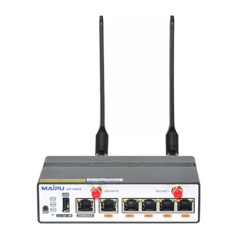
1 Router Introduction
MP1900X series router is a desktop access router independently developed by
Maipu, which includes two product models: MP1900X-12-AC and
MP1900X-22-AC.
This chapter mainly describes the specifications of MP1900X series router.
1.1 MP1900X-12-AC Appearance and Hardware Structure
The dimension of MP1900X-12-AC is 340mm × 260mm × 44.2mm (W x D x H).
The front appearance diagram of MP1900X-12-AC is shown in Figure 1-1, and
the rear appearance diagram is shown Figure 1-2.
Figure 1-1 The front appearance diagram of MP1900X-12-AC
1. Reset button 2. Function status indicator
3.USB interface 4.RJ45 CONSOLE port
5.1000Base-X SFP Ethernet optical
interface
6.1000Base-T Ethernet electrical
interface
7. Port status indicator

Router Introduction
MP1900X Series Router Installation Manual
1-2 copyright2019 Maipu, all rights reserved
Figure 1-2 The rear appearance diagram of MP1900X-12-AC
1. Fan outlet 2. Power switch
3. Power socket 4. Grounding screw
5.S1 slot of RM2B interface sub card 6.S2 slot of RM2B interface sub card
1.2 MP1900X-22-AC Appearance and Hardware Structure
The dimension of MP1900X-22-AC is 340mm × 260mm × 44.2mm (W x D x H).
The front appearance diagram of MP1900X-22-AC is shown in Figure 1-3, and
the rear appearance diagram is shown Figure 1-4.
Figure 1-3 The front appearance diagram of MP1900X-22-AC
1. Reset button 2. Function status indicator
3.USB interface 4.RJ45 CONSOLE port
5.USB CONSOLE port 6.1000Base-X SFP Ethernet optical
interface
7.1000Base-T Ethernet electrical
interface
8.1000Base-T Ethernet electrical
interface
9. Port status indicator

MP1900X Series Router Installation Manual Router Introduction
copyright2019 Maipu, all rights reserved 1-3
Figure 1-4 The rear appearance diagram of MP1900X-22-AC
1. Fan outlet 2. Power switch
3. Power socket 4. Grounding screw
5.S1 slot of RM2B interface sub card 6.S2 slot of RM2B interface sub card
1.3 Panel Specifications of MP1900X Series Router
The interface description is as shown in the following table:
Table 1-1 Interfaces on the front panel of MP1900X series router
Interface Name Description
Reset function button Press it for 3s, and the system restarts
and restores the factory setting
USB One USB interface, USB2.0 standard
CONSOLE Console port, one RJ45 interface, asyn
series port, default baud rate: 9600bps
Micro USB Console port, one Micro USB interface
GE0~GE4 port WAN port
MP1900X-12-AC: 1 GEF
MP1900X-22-AC: 1 GEF +4 GET
GE0/0~ GE0/7 port LAN port/ WAN port
Eight RJ45 interface,
10M/100M/1000M Ethernet port,
support auto crossing of data receiving
and sending
MP1900X-12-AC: eight ports
MP1900X-22-AC: eight ports
The meanings of the panel indicators are as follows:

Router Introduction
MP1900X Series Router Installation Manual
1-4 copyright2019 Maipu, all rights reserved
Table 1-2 The meanings of the panel indicators
Name Indicator
Color
Status Description
SYS Green Flash: indicates that the router works
properly.
Off/On: indicates the router works
abnormally.
PWR Green on: indicates that the system power
status is normal.
off: indicates the system power alarm
FAN Green on: indicates that the system fan status is
normal.
off: indicates that the system fan status is
alarm
USB Green on: indicates that the USB device works
properly.
off: indicates that no USB device is
installed or the USB device is removed.
flash: indicates that the USB device is
transmitting data.
CONSOLE RXD: green Off: indicates that no data is transmitted
over the port.
Flash: indicates that data is transmitted
over the port.
TXD: yellow
GE Green on: indicates that the port is up.
off: indicates that the port is down.
Flash: indicates that data is transmitted
over the port.
1.4 Air Passage of MP1900X Series Router
The air flow direction of MP1900X series router chassis is left in and right out,
and the diagram is as follows:
This manual suits for next models
2
Table of contents
Other Maipu Network Router manuals

Maipu
Maipu SM3100-9TC-AC Manual

Maipu
Maipu MP1800-3 User manual

Maipu
Maipu MP7500 User manual

Maipu
Maipu MP1800X-40 User manual

Maipu
Maipu MP2600C Series User manual

Maipu
Maipu SM3300-28FX User manual

Maipu
Maipu S2000-8/16 10/100Mbps Ethernet Switch User manual

Maipu
Maipu MP2801 User manual

Maipu
Maipu MP2800 Series User manual

Maipu
Maipu SM3100-28TC-AC Manual