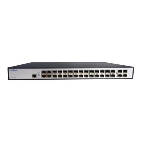
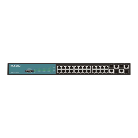
Maipu SM3100-9TC-AC Manual

S3100 Install Manual (For S3100-
9/18/26TC (TP))
V5.0
Maipu Communication Technology Co., Ltd
No. 16, Jiuxing Avenue
Hi-tech Park
Chengdu, Sichuan Province
People’s Republic of China - 610041
Tel: (86) 28-85148850, 85148041
Fax: (86) 28-85148948, 85148139
URL: http:// www.maipu.com
Email: [email protected]
Maipu Confidential & Proprietary Information Page 1 of 26

S3100 Install Manual (For S3100-9/18/26TC (TP)) V5.0
All rights reserved. Printed in the People’s Republic of China.
No part of this document may be reproduced, transmitted, transcribed, stored in a retrieval system, or translated into any
language or computer language, in any form or by any means, electronic, mechanical, magnetic, optical, chemical, manual
or otherwise without the prior written consent of Maipu Communication Technology Co., Ltd.
Maipu makes no representations or warranties with respect to this document contents and specifically disclaims any implied
warranties of merchantability or fitness for any specific purpose. Further, Maipu reserves the right to revise this document
and to make changes from time to time in its content without being obligated to notify any person of such revisions or
changes.
Maipu values and appreciates comments you may have concerning our products or this document. Please address comments
to:
Maipu Communication Technology Co., Ltd
No. 16, Jiuxing Avenue
Hi-tech Park
Chengdu, Sichuan Province
People’s Republic of China - 610041
Tel: (86) 28-85148850, 85148041
Fax: (86) 28-85148948, 85148139
URL: http:// www.maipu.com
Email: [email protected]
All other products or services mentioned herein may be registered trademarks, trademarks, or service marks of their
respective manufacturers, companies, or organizations.
Maipu Confidential & Proprietary Information Page 2 of 26

S3100 Install Manual (For S3100-9/18/26TC (TP)) V5.0
Maipu Feedback Form
Your opinion helps us improve the quality of our product documentation
and offer better services. Please fax your comments and suggestions to
Document Title S3100 Install Manual (For S3100-9/18/26TC (TP)) V5.0
Product
Version Document
Revision
Number
1.0
Presentation:
(Introductions, procedures, illustrations, completeness, arrangement, appearance)
Good Fair Average Poor
Accessibility:
(Contents, index, headings, numbering)
Good Fair Average Poor
Evaluate this
document
Editorial:
(Language, vocabulary, readability, clarity, technical accuracy, content)
Good Fair Average Poor
Your
suggestions to
improve the
document
Please check suggestions to improve this document:
Improve introduction Make more concise
Improve Contents Add more step-by-step procedures/tutorials
Improve arrangement Add more technical information
Include images Make it less technical
Add more detail Improve index
If you wish to be contacted, complete the following:
Name Company
Postcode Address
Telephone E-mail
Maipu Confidential & Proprietary Information Page 3 of 26

S3100 Install Manual (For S3100-9/18/26TC (TP)) V5.0
Contents
Introduction ...............................................................................................5
Product Brief ..........................................................................................................5
Physical Specifications.............................................................................................7
Appearance............................................................................................................9
Front Panel .............................................................................................................................9
Back Panel............................................................................................................................11
LEDs.....................................................................................................................................12
Device Installation .................................................................................. 17
Installation Notice.................................................................................................17
Environmental Requirements.................................................................................................17
Installation Notice..................................................................................................................21
Security Warnings.................................................................................................................21
Installation Preparation .........................................................................................22
Verify the Package Contents ..................................................................................................22
Required Tools and Materials .................................................................................................22
Installation Guide..................................................................................................22
Installing the Switch..............................................................................................................22
Connecting Console...............................................................................................................23
SFP Transceiver Installation ...................................................................................................24
Copper Cable/Fiber Cable Connection.....................................................................................24
Power Supply Connection ......................................................................................................25
Maipu Confidential & Proprietary Information Page 4 of 26
S3100 Install Manual (For S3100-9/18/26TC (TP)) V5.0
Introduction
Product Brief
My POWER S3100 series switch includes nine models:
SM3100-9TC-AC:
Figure 1-1 SM3100-9TC-AC switch
SM3100-9TC-DC48:
Figure 1-2 SM3100-9TC-DC48 switch
SM3100-9TP-AC:
Maipu Confidential & Proprietary Information Page 5 of 26

S3100 Install Manual (For S3100-9/18/26TC (TP)) V5.0
Figure 1-3 SM3100-9TP-AC switch
SM3100-9TP-DC48:
Figure 1-4 SM3100-9TP-DC48 switch
SM3100-18TC-AC:
Figure 1-5 SM3100-18TC-AC switch
SM3100-26TC-AC (S3026G-M-AC V2):
Figure 1-6 SM3100-26TC-AC (S3026G-M-AC V2) switch
SM3100-26TC-DC48:
Maipu Confidential & Proprietary Information Page 6 of 26

S3100 Install Manual (For S3100-9/18/26TC (TP)) V5.0
Figure 1-7 SM3100-26TC-DC48 switch
SM3100-26TP-AC:
Figure 1-8 SM3100-26TP-AC switch
SM3100-26TP-DC48:
Figure 1-9 SM3100-26TP-DC48 switch
Physical Specifications
zConsole Port
1 RJ-45 serial console port
zAC/DC Power Input
AC: 100 ~ 240VAC,50 ~ 60Hz
zPower Consumption
SM3100-9TC-AC: max 15W
Maipu Confidential & Proprietary Information Page 7 of 26

S3100 Install Manual (For S3100-9/18/26TC (TP)) V5.0
SM3100-9TC-DC48: max 15W
SM3100-9TP-AC: max 160W
SM3100-9TP-DC48: max 160W
SM3100-18TC-AC: max 20W
SM3100-26TC-AC (S3026G-M-AC V2): max 25W
SM3100-26TC-DC48: max 25W
SM3100-26TP-AC: max 500W
SM3100-26TP-DC48: max 500W
zOperating Temperature
0°C ~ 50°C
zStorage Temperature
-40°C ~ 70°C
zRelative Humidity
10% ~ 90%, no condensate
zDimension
SM3100-9TC-AC: (W * H * D) 282.2mm×44mm×178mm
SM3100-9TC-DC48: (W * H * D) 442.9mm×44mm×230.2mm
SM3100-9TP-AC: (W * H * D) 442.9mm×44mm×230.2mm
SM3100-9TP-DC48: (W * H * D) 442.9mm×44mm×230.2mm
SM3100-18TC-AC: (W * H * D) 442.9mm×44mm×230.2mm
SM3100-26TC-AC (S3026G-M-AC V2): (W * H * D) 442.9mm×44mm×230.2mm
SM3100-26TC-DC48: (W * H * D) 442.9mm×44mm×230.2mm
SM3100-26TP-AC: (W * H * D) 442.9mm×44mm×230.2mm
SM3100-26TP-DC48: (W * H * D) 442.9mm×44mm×230.2mm
zWeight
SM3100: Approximate 4kg
zMean Time Between Failure
Min. 80, 000 Hours MTBF
Maipu Confidential & Proprietary Information Page 8 of 26

S3100 Install Manual (For S3100-9/18/26TC (TP)) V5.0
Appearance
Front Panel
SM3100-9TC-AC front panel has eight 10/100Base-T ports, one Combo port (one
RJ-45 and one SFP port), one Console port and 19 LEDs.
The front panel of SM3100-9TC-AC switch:
Figure 1-10 Front panel of SM3100-9TC-AC
SM3100-9TC-DC48 front panel has eight 10/100Base-T ports, one Combo port
(one RJ-45 and one SFP port), one Console port and 19 LEDs.
The front panel of SM3100-9TC-DC48 switch:
Figure 1-11 Front panel of SM3100-9TC-DC48
SM3100-9TP-AC front panel has eight 10/100Base-T ports, one Combo port (one
RJ-45 and one SFP port), one Console port and 27 LEDs.
The front panel of SM3100-9TP-AC switch:
Figure 1-12 Front panel of SM3100-9TP-AC
SM3100-9TP-DC48 front panel has eight 10/100Base-T ports, one Combo port
(one RJ-45 and one SFP port), one Console port and 27 LEDs.
The front panel of SM3100-9TP-DC48 switch:
Figure 1-13 Front panel of SM3100-9TP-DC48
Maipu Confidential & Proprietary Information Page 9 of 26

S3100 Install Manual (For S3100-9/18/26TC (TP)) V5.0
SM3100-18TC-AC front panel has 16 10/100Base-T ports, two Combo ports (two
RJ-45 and two SFP ports), one Console port and 37 LEDs.
The front panel of SM3100-18TC-AC switch:
Figure 1-14 Front panel of SM3100-18TC-AC
SM3100-26TC-AC (S3026G-M-AC V2) front panel has 24 10/100Base-T ports, two
Combo ports (two RJ-45 and two SFP ports), one Console port and 53 LEDs.
The front panel of SM3100-26TC-AC (S3026G-M-AC V2) switch:
Figure 1-15 Front panel of SM3100-26TC-AC (S3026G-M-AC V2)
SM3100-26TC-DC48 front panel has 24 10/100Base-T ports, two Combo ports
(two RJ-45 and two SFP ports), one Console port and 53 LEDs.
The front panel of SM3100-26TC- DC48 switch:
Figure 1-16 Front panel of SM3100-26TC-DC48
SM3100-26TP-AC front panel has 24 10/100Base-T ports, two Combo ports (two
RJ-45 and two SFP ports), one Console port and 77 LEDs.
The front panel of SM3100-26TP-AC switch:
Figure1-17 Front panel of SM3100-26TP-AC
SM3100-26TP-DC48 front panel has 24 10/100Base-T ports, two Combo ports (two
RJ-45 and two SFP ports), one Console port and 77 LEDs.
The front panel of SM3100-26TP-DC48 switch:
Maipu Confidential & Proprietary Information Page 10 of 26

S3100 Install Manual (For S3100-9/18/26TC (TP)) V5.0
Figure 1-18 Front panel of SM3100-26TP-DC48
Back Panel
The back panel of SM3100-9TC-AC, SM3100-18TC-AC, and SM3100-26TC-
AC (S3026G-M-AC V2) has one 220V AC power receptacle, as follows:
Figure 1-19 Back panel of SM3100-9TC-AC
Figure 1-20 Back panel of SM3100-18TC-AC
Figure 1-21 Back panel of SM3100-26TC-AC (S3026G-M-AC V2)
The back panel of SM3100-9TC-DC48 and SM3100-26TC-DC48 has one DC
48V power socket and one switch button, as follows:
Figure 1-22 Back panel of SM3100-9TC-DC48
Figure 1-23 Back panel of SM3100-26TC-DC48
The back panel of SM3100-9TP-DC48 has one DC 52V power socket, one
switch button, and one ventilation hole, as follows:
Maipu Confidential & Proprietary Information Page 11 of 26

S3100 Install Manual (For S3100-9/18/26TC (TP)) V5.0
Figure 1-24 Back panel of SM3100-9TP-DC48
The back panel of SM3100-26TP-DC48 has one 52V power socket, one
switch button, and two ventilation holes, as follows:
Figure 1-25 Back panel of SM3100-26TP-DC48
The back panel of SM3100-9TP-AC has one 220V power socket and three
ventilation holes, as follows:
Figure 1-26 Back panel of SM3100-9TP-AC
The back panel of SM3100-26TP-AC has one 220V power socket, one DC
52V power socket and two ventilation holes, as follows:
Figure 1-27 Back panel of SM3100-26TP-AC
LEDs
MyPower S3100 series switch include port indicator and system status
indicator. The meanings of the LEDs are the same.
Port Indicator Description
Figure 1-28 SM3100-9TC-AC/ SM3100-9TC-DC48 LED diagram
Table 1-1 SM3100-9TC-AC/ SM3100-9TC-DC48 port indicator description
Maipu Confidential & Proprietary Information Page 12 of 26

S3100 Install Manual (For S3100-9/18/26TC (TP)) V5.0
Panel Symbol Status Description
On (Green) The port is linked successfully
Flash(Green) The port is linked successfully, and
receives/sends data
Port1-8(LINK/ACT)
Off The port is not linked
On (Green) The port is linked successfully
Flash(Green) The port is linked successfully, and
receives/sends data
PortG1(LINK/ACT)
Off The port is not linked
On (Green) The port is linked as 100Mbps.
Port1-8 (SPEED) Off The port is linked as 10Mbps or in the down
state.
On (Green) The port is linked as 1000Mbps.
PortG1 (SPEED) Off The port is linked as 10/100Mbps or in the
down state.
Figure1-29 SM3100-9TP-AC/ SM3100-9TP-DC48 LED diagram
Table 1-2 SM3100-9TP-AC/ SM3100-9TP-DC48 port indicator description
Panel Symbol Status Description
On (Green) The port is linked successfully
Flash(Green) The port is linked successfully, and
receives/sends data
Port1-8(LINK/ACT)
Off The port is not linked
On (Green) The port is linked successfully
Flash(Green) The port is linked successfully, and
receives/sends data
PortG1(LINK/ACT)
Off The port is not linked
On (Green) The port is linked as 100Mbps.
Port1-8 (SPEED) Off The port is linked as 10Mbps or in the
down state.
On (Green) The port is linked as 1000Mbps.
PortG1 (SPEED) Off The port is linked as 10/100Mbps or in
the down state.
Maipu Confidential & Proprietary Information Page 13 of 26

S3100 Install Manual (For S3100-9/18/26TC (TP)) V5.0
Figure 1-30 SM3100-18TC-AC LED diagram
Table 1-3 SM3100-18TC-AC port indicator description
Panel Symbol Status Description
On (Green) The port is linked successfully
Flash(Green) The port is linked successfully, and
receives/sends data
Port1-16(LINK/ACT)
Off The port is not linked
On (Green) The port is linked successfully
Flash(Green) The port is linked successfully, and
receives/sends data
PortG1/G2(LINK/ACT)
Off The port is not linked
On (Green) The port is linked as 100Mbps.
Port1-16 (SPEED) Off The port is linked as 10Mbps or in the
down state.
On (Green) The port is linked as 1000Mbps.
PortG1/G2 (SPEED) Off The port is linked as 10/100Mbps or in
the down state.
Figure 1-31 SM3100-26TC-AC (S3026G-M-AC V2)/SM3100-26TC-DC48 LED
diagram
Table 1-4 SM3100-26TC-AC (S3026G-M-AC V2)/ SM3100-26TC-DC48 port
indicator description
Panel Symbol Status Description
On (Green) The port is linked successfully
Flash(Green) The port is linked successfully, and
receives/sends data
Port1-24(LINK/ACT)
Off The port is not linked
On (Green) The port is linked successfully
Flash(Green) The port is linked successfully, and
receives/sends data
PortG1/G2(LINK/ACT)
Off The port is not linked
On (Green) The port is linked as 100Mbps.
Port1-24 (SPEED) Off The port is linked as 10Mbps or in the
down state.
On (Green) The port is linked as 1000Mbps.
PortG1/G2 (SPEED) Off The port is linked as 10/100Mbps or in
the down state.
Maipu Confidential & Proprietary Information Page 14 of 26

S3100 Install Manual (For S3100-9/18/26TC (TP)) V5.0
Figure 1-32 SM3100-26TP-AC/ SM3100-26TP-DC48 LED diagram
Table 1-5 SM3100-26TP-AC/ SM3100-26TP-DC48 port indicator
description
Panel Symbol Status Description
On (Green) The port is linked successfully
Flash(Green) The port is linked successfully, and
receives/sends data
Port1-24(LINK/ACT)
Off The port is not linked
On (Green) The port is linked successfully
Flash(Green) The port is linked successfully, and
receives/sends data
PortG1/G2(LINK/ACT)
Off The port is not linked
On (Green) The port is linked as 100Mbps.
Port1-24 (SPEED) Off The port is linked as 10Mbps or in the
down state.
On (Green) The port is linked as 1000Mbps.
PortG1/G2 (SPEED) Off The port is linked as 10/100Mbps or in
the down state.
System Status Indicator Description
Figure 1-33 SM3100 LED diagram
Table 1-6 SM3100 system indicator description
LED Status Description
On (Green) The internal power is operating normally
Power Off Power is off or error
Maipu Confidential & Proprietary Information Page 15 of 26

S3100 Install Manual (For S3100-9/18/26TC (TP)) V5.0
PoE Indicator Description
Figure 1-34 SM3100-9TP-AC/ SM3100-9TP-DC48 LED diagram
Table 1-7 SM3100-9TP-AC/ SM3100-9TP-DC48 POE indicator description
LED Status Description
Green Port is power on
PoE Off Port is power off
Figure 1-35 SM3100-26TP-AC/ SM3100-26TP-DC48 LED diagram
Table 1-8 SM3100-26TP-AC/ SM3100-26TP-DC48 POE indicator description
LED Status Description
Green Port is power on
POE Off Port is power off
Maipu Confidential & Proprietary Information Page 16 of 26

S3100 Install Manual (For S3100-9/18/26TC (TP)) V5.0
Device Installation
Installation Notice
To ensure the proper operation of MyPower S3100 series switch and your
physical security, please read carefully the following installation guide.
Environmental Requirements
zThe switch must be installed in a clean area. Otherwise, the switch
may be damaged by electrostatic adherence.
zMaintain the temperature within 0 to 50 °C and the humidity within
10% to 90%, non-condensing.
zThe switch must be put in a dry and cool place. Leave sufficient
spacing around the switch for good air circulation.
zThe switch must work in AC 100~240VAC (50/60Hz), DC with POE -
46~-57VDC and DC without POE -40~-57VDC.
zThe switch must be well grounded in order to avoid ESD damage and
physical injury of people.
zThe switch should avoid the sunlight perpendicular incidence. Keep the
switch away from heat sources and strong electromagnetic
interference sources.
zThe switch must be mounted to a standard 19’’ rack or placed on a
clean level desktop.
Dust and Particles
Dust is harmful to the safe operation of S3100 series switch. Dust can lead
to electrostatic adherence, especially likely under low relative humidity,
causing poor contact of metal connectors or contacts. Electrostatic
adherence will result in not only reduced product lifespan, but also
increased chance of communication failures. The recommended value for
dust content and particle diameter in the site is shown below:
Maipu Confidential & Proprietary Information Page 17 of 26

S3100 Install Manual (For S3100-9/18/26TC (TP)) V5.0
Max Diameter (µm) 0.5 1 3 5
Max Density
(particles/m³) 1.4×1057×1052.4×1051.3×105
Table 2-1 Environmental Requirements: Dust content
In addition, salt, acid and sulfide in the air are also harmful to the switch.
Such harmful gases will aggravate metal corrosion and the aging of some
parts. The site should avoid harmful gases, such as SO2, H2S, NO2, NH3
and Cl2, etc. The table below details the threshold value.
Gas Average (mg/m³) Max (mg/m³)
SO20.2 1.5
H2S 0.006 0.03
NO20.04 0.15
NH30.05 0.15
Cl20.01 0.3
Table 2-2 Environmental Requirements: Particles
Temperature and Humidity
The switch installation site should maintain a desirable temperature and
humidity. High-humidity conditions can cause electrical resistance
degradation or even electric leakage, degradation of mechanical properties
and corrosion of internal components. Extreme low relative humidity may
cause the insulation spacer to contract, making the fastening screw
insecure. Furthermore, in dry environments, static electricity is liable to be
produced and cause harm to internal circuits. Temperature extremes can
cause reduced reliability and premature aging of insulation materials, thus
reducing the switch’s working lifespan. In the hot summer, it is
recommended to use air-conditioners to cool down the site. And the cold
winter, it is recommenced to use heaters.
The recommended temperature and humidity are shown below:
Temperature: Relative humidity
Long term condition Short term condition Long term condition Short term condition
15 ~ 30°C 0 ~ 50°C 40 ~ 65% 10 ~ 90%
Table2-3 Environmental Requirements: Temperature and Humidity
Maipu Confidential & Proprietary Information Page 18 of 26

S3100 Install Manual (For S3100-9/18/26TC (TP)) V5.0
Caution
A sample of ambient temperature and humidity should be taken at 1.5m
above the floor and 0.4m in front of the switch rack, with no protective
panel covering the front and rear of the rack. Short term working
conditions refer to a maximum of 48 hours of continued operation and an
annual cumulative total of less than 15 days. Formidable operation
conditions refers to the ambient temperature and relative humidity value
that may occur during an air-conditioning system failure, and normal
operation conditions should be recovered within 5 hours.
Power Supply
It is adopted module switch power for the switch, the input parameters of
power are shown below:
The AC input voltage: 100~240VAC
The frequency: 50~60Hz
DC input: with POE -46~-57VDC
Without POE -40~-57VDC
Before powering on the power supply, please check the input power to
ensure proper grounding of the power supply system. The input power for
the switch should be reliable and secure; a voltage adaptor can be used if
necessary. The building’s circuit protection system should include in the
circuit a fuse or circuit-breaker of no greater than 240 V, 10 A. It is
recommended to use a UPS for more reliable power supplying. .
Caution
Improper power supply system grounding, extreme fluctuation of the input
source, and transients (or spikes) can result in larger error rate, or even
hardware damage!
Preventing Electrostatic Discharge Damage
Static electric can cause damage to internal circuits, even the entire switch.
Follow these guidelines for avoiding ESD damage:
zEnsure proper earth grounding of the device;
zPerform regular cleaning to reduce dust;
zMaintain proper temperature and humidity;
Maipu Confidential & Proprietary Information Page 19 of 26

S3100 Install Manual (For S3100-9/18/26TC (TP)) V5.0
zAlways wear an ESD wrist strap and antistatic uniform when in contact
with circuit boards.
Anti-interference
All sources of interference, whether from the device/system itself or the
outside environment, will affect operations in various ways, such as
capacitive coupling, inductive coupling, electromagnetic radiation, common
impedance (including the grounding system) and cables/lines (power
cables, signal lines, and output lines). The following should be noted:
zPrecautions should be taken to prevent power source interruptions;
zProvide the system with a dedicated grounding, rather than sharing
the grounding with the electronic equipment or lightning protection
devices.
zKeep away from high power radio transmitters, radar transmitters,
and high frequency strong circuit devices.
zProvide electromagnetic shielding if necessary.
Rack Configuration
The dimension of the switch is designed to be mounted on a standard 19’’
rack, DCS-3650’s dimensions are 440mm x 44mm x 229mm (W x H x D).
Please ensure good ventilation for the rack.
zEvery device in the rack will generate heat during operation, therefore
vent and fans must be provided for an enclosed rack, and devices
should not be stacked closely.
zWhen mounting devices in an open rack, care should be taken to
prevent the rack frame from obstructing the switch ventilation
openings. Be sure to check the positioning of the switch after
installation to avoid the aforementioned.
Caution
If a standard 19’’ rack is not available, the switch can be placed on a clean
level desktop, leave a clearance of 10mm around the switch for ventilation,
and do not place anything on top of the switch.
Maipu Confidential & Proprietary Information Page 20 of 26
This manual suits for next models
9
Table of contents
Other Maipu Network Router manuals

Maipu
Maipu MP1800 Manual

Maipu
Maipu MP2800 Series User manual

Maipu
Maipu MP1800-3 User manual

Maipu
Maipu SM3300-28FX User manual

Maipu
Maipu SM3100-28TC-AC Manual

Maipu
Maipu SM4200-28FC Manual

Maipu
Maipu MP1800X-40 User manual

Maipu
Maipu MP1900X Series User manual

Maipu
Maipu MP2801 User manual

Maipu
Maipu S2000-8/16 10/100Mbps Ethernet Switch User manual
Popular Network Router manuals by other brands

MikroTik
MikroTik 751G-2HnD Quick setup guide

ZyXEL Communications
ZyXEL Communications Dimension GS-3012 Specification sheet

GRASS VALLEY
GRASS VALLEY CR6400 Series user guide

Comnet
Comnet CNGE8FX4TX4MS Installation and operation manual

TP-Link
TP-Link TD-W8960N user guide

Huawei
Huawei AR530 Series Configuration guide