17. GENERAL MAINTENANCE
Beyond replacing batteries and fuses, do not attempt to repair or service the
product unless you are qualified to do so and have the relevant calibration,
performance test, and service instructions.
1. Do not operate the product around hot, wet, flammable, explosive or magnetic
environments.
2. Clean the product with damp cloth and mild detergent; do not use abrasives
or solvents.
3. Remove the input signals before you clean the product.
4. Remove the batteries if you will not use the product for a long time to prevent
possible battery leak.
5. When “ ” is shown on the display, batteries shall be replaced as below:
1. Loosen the screw and remove the battery cover;
2. Replace the used batteries with new batteries of the same type;
3. Place the battery cover back and fasten the screw.
6. Replace fuses as above steps. Use only fuses of the same type as the original
ones.
WARNING:
1. Do NOT exceed the “maximum value” indicated in the Specification;
2. Do NOT input voltage at the Current Mode, the Resistance Mode, the
Diode Mode, the Continuity Mode, or the Temperature Mode;
3. Do NOT use the product when the batteries or the battery cover is
not placed correctly;
4. Turn off the product and remove the test leads from the test points
before changing batteries or fuses.
18. TROUBLESHOOTING
If your product does not function as normal, the following steps may assist
you. If the problem still cannot be solved, please contact your dealer.
Problem Possible Reason
Display Malfunction Low battery; replace batteries
Symbol Replace batteries
No current input Replace fuse
6. MEASURE AC/DC VOLTAGE
1. The minimum voltage of this product is 0.8V. When the measured voltage is
higher than 0.8V, the product will display the reading;
2. Connect the black test lead to the COM Terminal and connect the red test lead
to the Terminal;
3. The DC or AC voltage will be matched automatically;
4. Touch the probes to the correct test points of the circuit to measure the
voltage;
5. Read the measured voltage on the display.
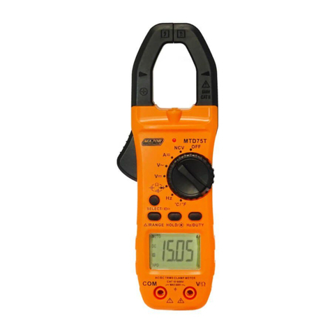
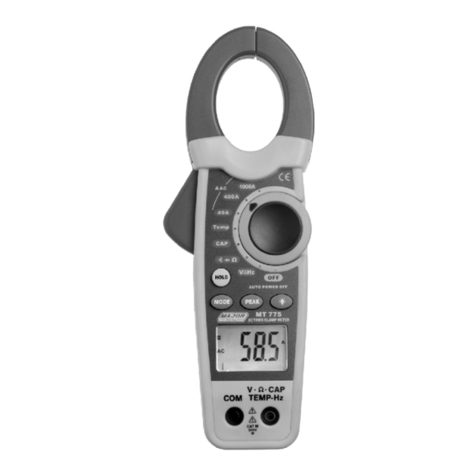
7. MEASURE AC/DC CURRENT
1. Turn power switch on.
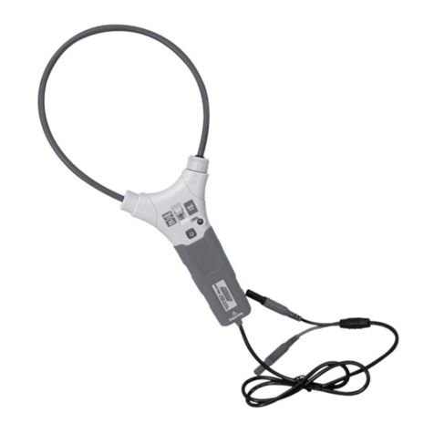
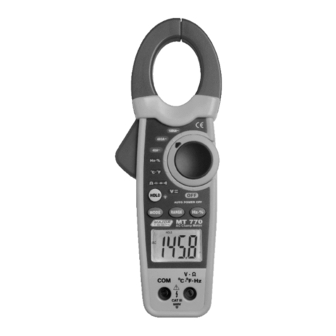
2. Push the jaw release and center the wire within the clamp jaws (as in the
picture). The wire should be in the marked position to keep measurement
accuracy.
3. Press the SEL button to select between AC or DC Amperage
4. Read the measured current on the display.
8. MEASURE RESISTANCE
1. Connect the black test lead to the COM Terminal and connect the red test lead
to the Terminal;
2. The resistance will be matched automatically;
3. Touch the probes to the desired test points of the circuit to measure the
resistance;
4. Read the measured resistance on the display.
9. MEASURE CONTINUITY / DIODE
1. Connect the black test lead to the COM Terminal and connect the red test lead
to the Terminal;
2. Press SEL / Power once to toggle to the Continuity/Diode Mode;
3. Touch the probes to the desired test points of the circuit;
4. The built-in beeper will beep when the resistance is lower than 50Ω, and the
indicator light will be on.
5. Measure diode: Connect the red probe to the anode side and the black probe
to the cathode side of the diode to be tested;
6. Read the forward biased voltage value on the display;
7. If the polarity of the test leads is reversed with diode polarity or the diode is
broken, the display reading shows “OL”.
10. MEASURE CAPACITANCE
1. Discharge all capacitors before you test capacitance.
2. Connect the black test lead to the COM Terminal and the red lead to the
Terminal.
3. Push Power button twice to enter the Capacitance Mode.
4. Connect the red probe to the anode side and the black probe to the cathode
side of the capacitor to be tested.
5. Read the measured capacitance value.
11. MEASURE FREQUENCY
1. Connect the black test lead to the COM Terminal and connect the red test lead
to the Terminal;
2. Press Hz / NCV button once for AC current frequency
3. Touch the probes to the desired test points of the circuit
4. Read the measured frequency value on the display.
12. MEASURE NCV
1. Press and hold Hz / NCV over 2 seconds to toggle to the NCV Mode;
2. Hold the product and move it around, the built-in beeper will beep when the
inner sensor detects AC voltage nearby. The stronger the voltage is, the
quicker the beeper beeps.
3. Put the red probe into the terminal, then use the red probe to touch the
Live line and Neutral line of the Main supply. You can judge the L-line or N-line
by the beeps, If you hear the strong beeps, this is the L-line. If you hear the
weak beeps or no beeps, it's a N-line.
13. MEASURE TEMPERATURE
1. Connect the black thermocouple probe to the COM Terminal and connect the
red thermocouple probe to the Terminal;
2. Press SEL / POWER once to toggle to the Temperature Mode after connecting
the test lead to Terminals, and the display will show the room temperature, to
switch ℃/℉, press SEL / POWER button once again;
3. Touch the probes to the desired test points;
4. Read the measured temperature on the display.
14. MEASURE INRUSH CURRENT
1. Turn power on - select AC Current, and press HOLD twice to toggle Inrush
Current Mode, the display will show “INRUSH”;
2. Push the jaw release and center the wire within the clamp jaws. The wire
should be in the marked position to keep measurement accuracy;
3. Turn on the engine or motor equipment, and the product will capture the
maximum current within 100ms when motor is starting;
4. Read the measured temperature on the display.
15. PEAK HOLD
1. Turn power on and Press HOLD once after connecting the test lead to
Terminals to toggle to Peak Hold Mode, the display will show “PEAK HOLD”;
2. Touch the probes to the desired test points of the circuit;
3. Read the measured voltage value on the display.
16. AUTO POWER OFF
1. The product automatically powers off after 15 minutes of inactivity;
2. The built-in beeper beeps 5 times 1 minute before power off;
3. To restart the product, press SELECT button;
4. To disable the Auto Power Off function, hold down the Hz / NCV button when
turning on the product, you will hear five beeps if you have successfully
disabled the function.
WARNING:
1. Do NOT exceed the “maximum value” indicated in the Specification.
2. Do NOT input voltage on the Current Mode, the Resistance Mode, the Diode
Mode, the Continuity Mode, or the Temperature Mode.
3. Do NOT use the product when the batteries or the battery cover is not placed
correctly.
4. Turn off the product and remove the test leads from the test points before
changing batteries or fuses.
18. TROUBLESHOOTING
If your product does not function as normal, the following steps may assist you. If
the problem still cannot be solved, please contact your dealer.
CAUTION: Do not input voltage on the Temperature Mode
CAUTION: Do not input voltage at the Continuity / Diode Mode.
CAUTION: Do not measure voltage that exceeds the MAX Value as indicated in
the Specifications. Do not touch high voltage circuit during measurements.
CAUTION: Do not measure current that exceeds the MAX Value as indicated in the
Specifications. Measure one wire at a time because current moving in different
directions will cancel each other out.
CAUTION: Disconnect circuit power and discharge all capacitors before you test
resistance. Do not input voltage at the Resistance Mode.
www.major-tech.com www.majortech.com.au
MAJOR TECH (PTY) LTD
South Africa Australia
V Ω Hz C˚
V Ω Hz C˚
V Ω Hz C˚
V Ω Hz C˚
V Ω Hz C˚
V Ω Hz C˚
V Ω Hz C˚
V Ω Hz C˚
