Makermade Standard Frame User manual

v 1.5 Updated 8.30.21 ©Maker Made, LLC
The Standard Frame
A guide to assembling the recommended 10ft top beam
frame for our MakerMade M2 CNC Kit.
Set-Up Guide for

TABLE OF CONTENTS
SECTION 1. Intro - 3
SECTION 2. Materials Needed - 4
SECTION 3. Building the Standard Frame
Building the canvas - 5
Attaching the motors - 6
Attaching the stud mounts - 7
Frame legs - 8
Attaching the canvas frame - 10
Leveling your frame -11
Optional skirts - 12
Attaching the chains - 13
Mounting the M2 to your frame - 14
Arduino DUE and shield - 15
SECTION 4. Appendices
Tips and warnings - 16
What’s in the box? - 17
Standard Frame Dimensions - 19
Custom Frame Tips - 20
2

Thanks for buying the M2 CNC Automated Cutting Machine and
welcome to the MakerMade family! The following instructions are
intended for beginners - with no prior CNC experience.
Here are some notes on the layout...
1. Setting up the M2 can be broken down into three main parts: building
the M2, building the frame (or mounting it on an existing Maslow frame),
and calibration. This guide covers the standard frame.
2. I’m Drew and I made this guide! My notes are tips and tricks to help you
along. They are in a different blue font and look like this:
Drew’s Note: Let us know how this guide can be improved. We love to hear from
you!
Drew’s notes are meant to answer some of the “why” questions you might
have and give you tips to get started. We suggest printing the guide in
color, if you want a paper copy.
3. Each step contains written instructions, a visual rendering of those
instructions, color coded pictures of sub-steps or parts needed for that
step, the hardware bag where you’ll find the parts you’ll need, and
underlined words are something that you should write on your frame in
pencil for reference.
We hope you enjoy setting up your kit, happy making!
INTRODUCTION
Here’s me and Spaghetti,
he’s not impressed with CNC
Like this Bag G in
orange
3
The biggest step to starting your M2 CNC adventure is to build the frame that will
hold your material and the M2 while it cuts. The M2 mounts for your frame are
included, but you will need to purchase the following from a local hardware store
to build the standard frame to cut 4ft x 8ft.
Drew’s Note: We recommend reading this entire section before beginning.
ASSEMBLING THE STANDARD FRAME
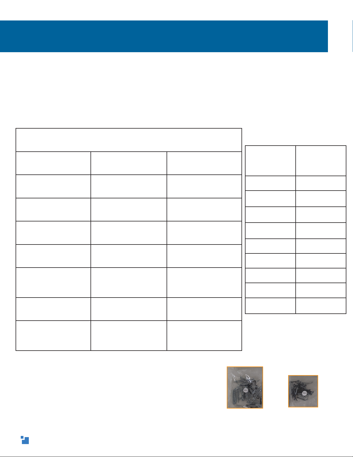
10ft Standard Frame - Materials Needed
Amount Needed Type Purpose
22in x 4in x 10ft Top and Bottom Beams
22in x 4in x 8ft Vertical Frame Legs
42in x 4in x 4ft Canvas Legs
22in x 4in x 3ft Horizontal Frame Legs
424in x 48in x 5/8in
Particle Board (1/2in thick
particle board, MDF, or
plywood will also work)
Canvas Wasteboards
1 (a second one is
optional)
1in x 6in x 8ft Bottom Skirt and
optional top skirt (see
Part 6)
2 (optional) 1in x 6in x 4ft Side Skirts (Cut a 1in x
6in x 8ft in two, if not
available in your area,
see Part 6)
Tools for
Building
the frame
Tools for M2
operation
Wrench Router
Hammer Dust Collection
System
Phillips
Screwdriver
2 Standard (4-
5lb) Sized Bricks
Drill / Impact
Driver
2+ Clamps
Tape Measure Material to Cut
Speed Square
Level
Pencil
Extra 1.5in and
2in screws
Short/Long frame mounting screws
Bag C and Bag D
Drew’s Note: Nearly every step uses short (1.5in) or long (2in)
wood screws. So, I’m going to leave the bag picture out of the
steps for redundancy’s sake. Just know that you’ll need a lot
of short and long wood screws are from Bags C and D (and
some extras). If you’re experienced with woodworking, feel
free to use any wood screw of your choice to build the frame.
4

1. (A) To build the canvas, lay the four 2in x 4in x 4ft canvas legs on their 2in edges and mark
with the with the word giraffe (or bottom) on one end of each.
(B) Measuring from the giraffe/bottom end on each, draw a line using a speed square at 9in
and 37in.
(C) Position two canvas legs about 4ft apart. Lay one of the 24in x 48in x 5/8in canvas
wasteboard on them with the legs flush with the 48in ends. Use the speed square to make
the wasteboard flush on the 9in line and screw it into the canvas supports with three long
wood screws, evenly spaced on the leg. Repeat with the other two legs with another canvas
wasteboard.
(D) On the 37in line, position another canvas wasteboard with the speed square and use a 2in x
4in board to support the top edge of the waste-
board while aligning and attaching. Using two
long wood screws per side. Repeat with the
other canvas wasteboards and legs to build the
second canvas.
Building the canvas
2in long wood screw
giraffe
giraffe
4ft
2in
Drew’s Note: Labeling the ends of the board ensures that
we are measuring from the same end of each board. This
mitigates small height differences in the 2in x 4in boards,
so the canvas wasteboards are the same height from the
floor on each canvas. I labeled my ends on the canvas
legs, ‘giraffes’ because giraffes are awesome!
giraffe
giraffe
37in (94cm)
9in (23cm)
2in
37in
(94cm)
9in
(23cm)
giraffe giraffe
5
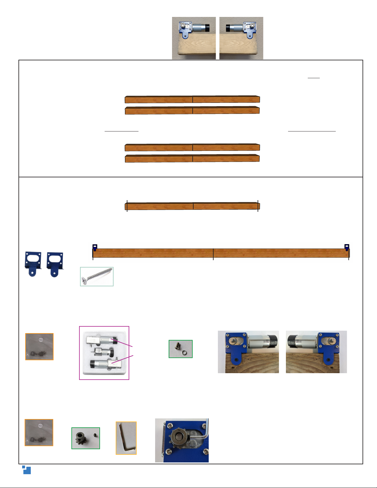
2. (A) Measure the actual length of the 2in x 4in x 10ft beams and mark the exact center of each
on a 4in face. Draw a straight line across the center with the speed square. Write top on a 2in
edge of each and extend the center line around the beam and across the top with the speed
square.
(B) On one beam, write top beam next to the center line. On the other, write bottom beam next
to the center.
3. (A) On the top beam, measure 5ft out from center on each side and draw a straight line with
the speed square on the top edge.
(B) Align the outside edge of the motor mounting brackets flush with the 5ft lines (as shown),
and attach them to the top beam. Use one short wood screw in the front and two in diagonal
holes in the top.
(C) Place one X/Y motor in each bracket, with the black, cylindrical ends toward the center. Use
the motor washers between the bracket and the screw head and fasten the motor screws to the
brackets.
(D) On each motor, attach the motor sprocket by inserting the set screw partially into the gear
hole. Align the set screw with the flat side of the motor shaft, push it all the way down, and
tighten it with 3mm hex wrench to prevent it from slipping.
Attaching the motors
1.5in short wood screw
top
top
center
top beam
bottom beam
motor mounting
brackets
X/Y motors
X/Y Motor
Hardware Bag E
X/Y Motor
Hardware Bag E
top
top
center
5ft 5ftcenter
5ft5ft
top top beam
center
Drew’s Note: If you have Loctite,
placing a bit on this set screw is a great
way to prevent it from loosening over
time.
6
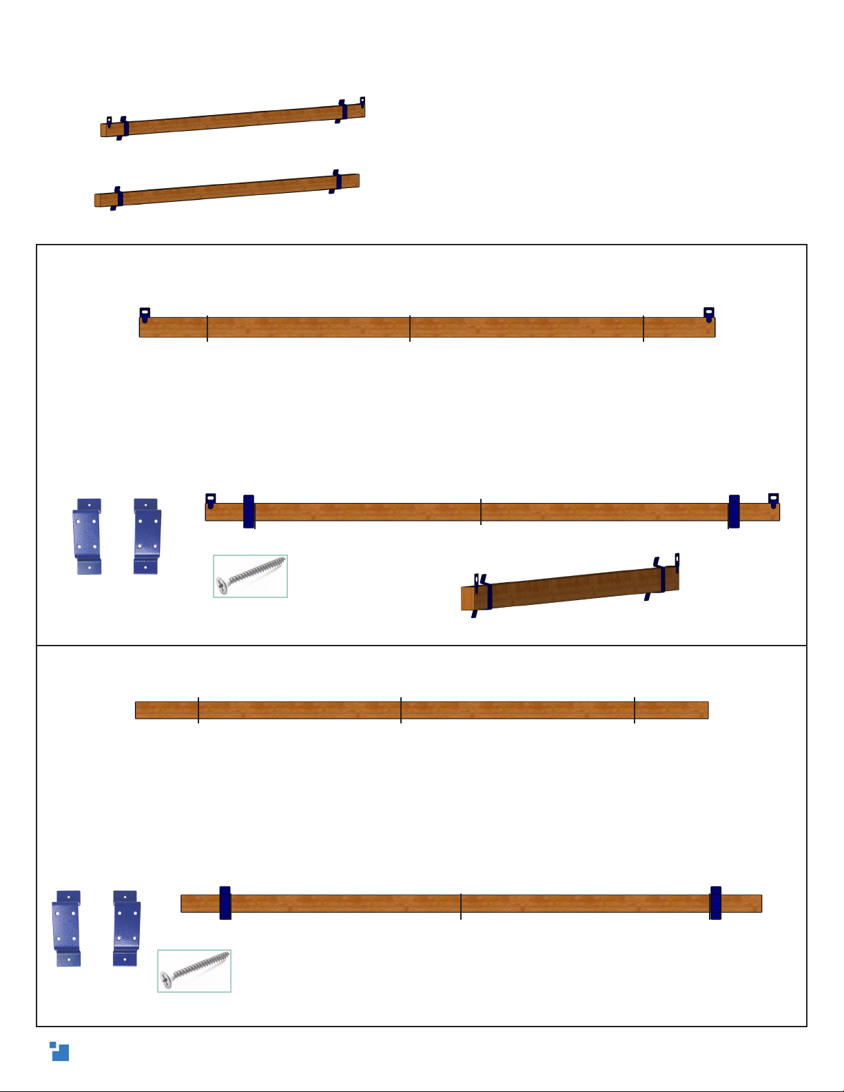
4. (A) On the front face of the top beam, measure and mark 51.5in (130.8cm) from the center on
each side. Draw a straight line with the speed square.
(B) Position a stud mount on the outside of each 51.5in line, with the shorter angle of the stud
mounts toward the top. On one side, push the bottom of the mount against the bottom of the top
beam, use a speed square as a guide to keep it on the 51.5in line, and screw it into the top beam
with four short wood screws. The bottom of the mount should be as flush as possible with the
bottom of the top beam and exactly perpendicular to the beam. Repeat on the other side. Use
the above Drew’s Note for mounting tips!
5. (A) On the front 4in face of the bottom beam, measure and mark 51.5in (130.8cm) from the
center on each side. Draw a straight line with the speed square.
(B) Exactly like attaching to the top beam, position a stud mount on the outside of each 51.5in
line, with the shorter angle of the stud mounts toward the top. On one side, push the bottom of
the mount against the bottom of the top beam, use a speed square as a guide to keep it on the
51.5in line, and screw it into the top beam with four short wood screws. The bottom of the mount
should be as flush as possible with the bottom of the top beam and exactly perpendicular to the
beam. Repeat on the other side.
Attaching the stud mounts
Drew’s Note: For the M2’s alignment calibration
calculation (that’s fun to say), we have to
make sure that the stud mounts are exactly
perpendicular to the beams. To ensure this,
attach each screw part-way before moving
to the next. Repeat on the other two holes and
screw in each from opposite sides by small
increments until they are all tight - just like
changing a tire.
1.5in short wood screw
center51.5in 51.5in
center
51.5in 51.5in
center51.5in 51.5in
center51.5in 51.5in
1.5in short wood screw
stud mount
Side view
stud mount
7
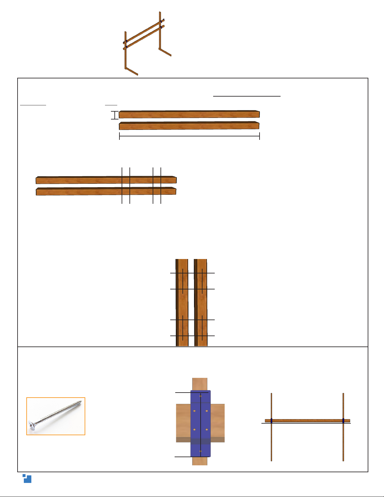
6. (A) Lay the 2in x 4in x 8ft vertical frame legs on the floor, on their 2in edges. Label them
something fun, so you remember that they are, or just vertical frame legs. On each board, write
bottom on one end and top on the other.
(B) Measuring from the bottom end, measure and mark at 55in (139.7cm) , 61.75in (156.8cm), 70in
(177.8cm), and 76.75in (194.9cm) up. Use the speed square to draw a straight line at each mark.
(C) Measure the actual center of each line across the side. Use the speed square to draw a
perpendicular line through the center of the 55in and 61.75in lines. Use the speed square to draw
another perpendicular line intersecting the 70in and 76.75in lines. Repeat on the other leg.
7. Arrange the vertical frame legs parallel on the floor, resting on their 2in edges. Position the
bottom beam on the legs, with the taller ends of the stud mounts flush with the 55in line. Center
the top and bottom holes of the stud mount on the perpendicular center line and attach with the
long wood screws.
Frame legs
Drew’s Note: The actual thickness of your
2in x 4in is around 1.5in. We want to find
the center to ensure that the stud mounts
are mounted perpendicular with the floor
and in the center of your 2in x 4in.
2in long wood screw
bottom
bottom
top
top
8ft
2in
61.75in
70in
55in 55in
61.75in
70in
76.75in 76.75in
bottom
bottom
top
top
55in 76.75in70in61.758in
55in
55in
61.75in
8

8. Position the top beam on the legs, with the taller side of the stud mounts flush with the 70in
line.
Repeat the process of step 7, by centering the top and bottom holes of the stud mount on the
perpendicular line and attaching with the long wood screws.
9. To attach the horizontal frame legs, write back on the ends of the 2in x 4in x 3ft boards. Align
the back end on the inside of the vertical frame legs at a 90 degree angle to make an L shape.
Use the speed square to ensure the 90 angle is square and flush with the back of the vertical
frame legs. Use three long wood screws in a triangle to attach each leg together.
Frame legs (continued)
2in long wood screw
2in long wood screw
70in
76.75in
70in
3ft
Isometric
view
Side view
3ft
Front view
9

~4in
~4in
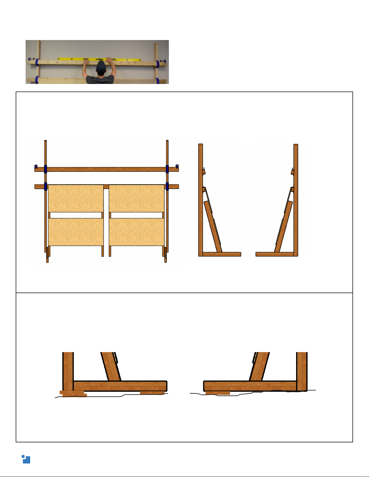
10. (A) Stand up your frame and push it against a wall. Lean your particle board
canvas from Part One inside of the frame legs. They should be pressed against the
support legs on each side, with about a 4in gap between them.
(B) From the back end of the horizontal frame legs, measure and mark 17.25in (43.8cm) out on
each. Angle the canvases, so that the inside of the angle is on the 17.25in line and the top of the
canvas is flat against the bottom beam. Attach to the canvases to the horizontal frame legs with
two long wood screws on each side.
(C) Attach the top of the canvases to the bottom beam using three evenly spaced short wood
screws on each.
Attaching the canvas Drew’s Note: WARNING: This frame is
designed to lean against a wall for
safety. If it is not against a wall, it could
tip over. For added safety, you can
toenail one of the vertical frame legs
into a stud or use an L-bracket (not-
included), similar to what you would
for an oven safety bracket. Look for a
stand-alone update coming soon.
1.5in short wood
screw
2in long wood
screw
17.25in
Side view
17.25in 17.25in
Left view Right view
10
11. (A) Check that your top and bottom beams are level. If they are not, they should be off by the
same amount, since your frame is square. Verify that the frame is level in the following places:
If your frame is level, you’re good to go!
(B) OPTIONAL If it isn’t level, first check your measurements from the previous steps to ensure
that your frame is square. Once your measurements are confirmed for squareness, use a few
shims (small pieces of wood or scrap material) under the back and front of the frame legs, on
one or both sides, until your frame is level. This is especially useful in locations that don’t have
level floors.
Front
Leveling your frame Drew’s Note: It’s very important that your frame
is square and level! All of the M2 calibrations are
based on a well built frame. If the frame isn’t level
and square, the M2 will slant when it cuts and
have all kinds of other small problems.
It will be very difficult, if not impossible to
calibrate properly.
Check here
Here Here
Here
Left Side Right Side
Here
Here Here
Here
Here Here
Drew’s Note: Once you’ve verified your frame is level in the locations in step A, you can
toenail the top and bottom of the vertical frame legs to the wall to keep the frame from
shifting over time.
ex. Left Side ex. Right Side
Unlevel floor
Unlevel floor
11

12. (A) Measure and mark the actual center of the 1in x 6in x 8ft bottom skirt.
(B) On the left canvas, measure and mark 1.5in (3.8cm) up from the bottom. Align one of the 8ft
skirts with the center line and attach it to the particle board, on that line, with one short wood
screw. Place the level on the skirt and rotate it up or down on the screw until it is level. When
level, attach it to the other canvas with another short wood screw. Add three more screws per
canvas to fully attach the bottom skirt.
(C) OPTIONAL: Similar to the bottom skirt, measure the actual length of the top skirt and mark
the center. Then, measure and mark 1.5in (3.8cm) down from the top of the left canvas. Align the
8ft skirt with the center line and attach it to the particle board on that line with one short wood
screw. Place the level on the skirt and rotate it on the screw until it is level. When level, attach
it to the other canvas with another short wood screw. Add two more screws per canvas to fully
attach the top skirt.
(D) OPTIONAL: For the side skirts, measure and mark 1.5in (3.8cm) in on each side of the
canvases, closest to the stud mounts. Attach a 4ft side skirt to each side using 4 short wood
screws.
Attaching the skirts
Drew’s Note: A skirt’s purpose is to act as a stabilizer for your
M2 when it gets near the edge while cutting and the sled
edge extends beyond your canvas. The bottom skirt makes
it easier to mount your material to cut, because it acts as a
support. As long as you’re within 1/4in (6mm) on your skirt
measure measurements and they are level, you’re fine. It’s
optional, so don’t sweat getting the skirt perfect.
1.5in short
wood screw
Drew’s Note: Just like your
frame, it’s very important
that the bottom skirt is level
and parallel with the top
beam! Your material will rest
on it and if your frame isn’t
square and level then your
cuts will be off!
Drew’s Note: Your skirts can be under 1in thick,
so you can use scrap material for them! It’s just
important that they are all the same thickness.
This is because if the material you’re cutting is less
than their thickness, you will need to elevate your
material. Otherwise, your sled will bump into the
skirt when it gets close to the edge.
1.5in short
wood screw
1.5in short
wood screw
12

12. (A) To attach the chains on the front of the top beam, measure and mark 1.5in (4cm) from
the bottom and 15in (38cm) toward the center, from the end of the top beam. Insert the small
nail through loop in the last chain link on one chain, and hammer it into that spot. Repeat on the
other side of the motor mounting brackets.
(B) From the nail, measure about 25.5in (65cm) toward the
center of the top beam and loop the chain around your
thumb,back toward the motor and above the nail. Drape
the top of the chain over the motor sprocket so it locks in
place. Repeat on the other side.
(C) On the right side, place the sprocket in the chain loop and attach the quick link through the
hole in the sprocket, with its opening facing away from beam. Don’t tighten the link. On the left
side, attach the spring and tighten the quick link, ensuring the link nut is facing away from the
beam.
(D) Carefully stretch out the spring from the left side to attach it to the other end to the open
quick link on the right side. Tighten the right quick link to lock the chains together.
Attaching the chains Drew’s Note: We recommend a friend help you connect
the spring and each person wear safety goggles
during stretching. The chain can snap back, causing
damage to people, pets, and surroundings!
Chain Mounting
Hardware Bag A
Spring Hardware Bag B
1.5in
15in
Drew’s Note: You can adjust the spring tension on your frame by moving the nails toward or away
from center. The most important part is that the spring keeps the tension on the chains. We use nails
to connect the chain to the frame, so if something goes awry, only the nails will be removed without
damaging your frame.
Chain Mounting
Hardware Bag A
25.5in
13
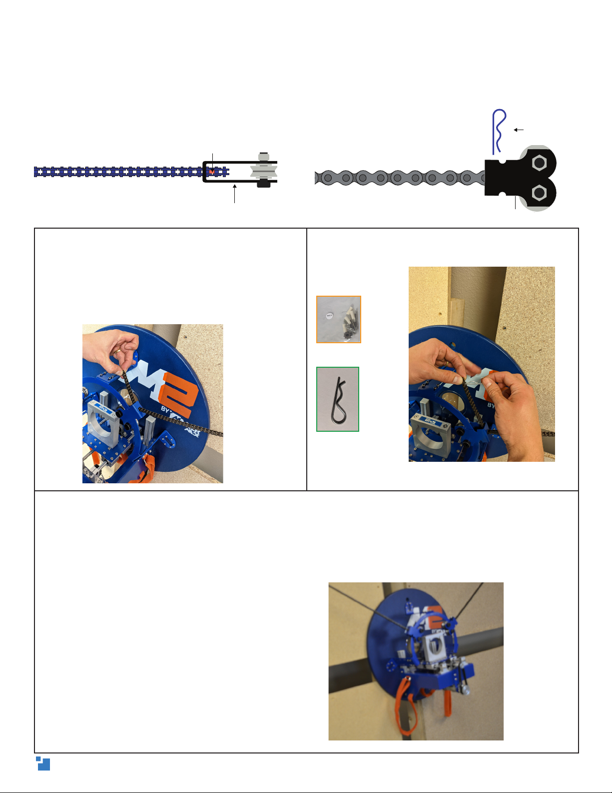
1. Hold the M2 sled against the wasteboard
near the right chain. Hold it against the frame
with your body weight or have a friend help
by holding it for you. Take the loose end of
one chain and thread up through the hole in
the roller bearing carriage.
2. Insert the cotter pin, with the flat side on
the right, into the second to last chain link to
attach.
3. Manually move the M2 to the center of the Wasteboard and have a friend pull the tension
on the opposite chain to around 20in from the nail to the spring. You can pull the chain
away from the motor sprocket, pull for more length, and set it back for the tension to hold,
and beware of it snapping. When you have enough slack in the chain, thread through the
opposite roller bearing carriage and attach with the other cotter pin into the second to last
chain link. Let go of the sled and it will rest against the canvas.
Drew’s Note: We recommend wearing safety goggles and having a friend help mount the sled to
the frame. The chain can slip off the sprockets, causing the spring to snap and hurt people, pets,
and surroundings. It’s also important to insert the cotter pin into the second to last link, for extra
safety of the chain attachment, as shown below.
Drew’s Note: Your M2 is ready to
calibrate! (Also, don’t forget to
securely attach your bricks with the
Velcro straps, if you waited until it was
mounted).
Mounting the M2 to the frame
Chain Mounting
Hardware Bag A
CARRIAGE MOUNT
CHAIN
INSERT COTTER PIN HERE
Roller bearing carriage
Cotter pin goes here
CARRIAGE MOUNT
COTTER
PIN
CHAIN
Roller bearing carriage
Cotter pin
14
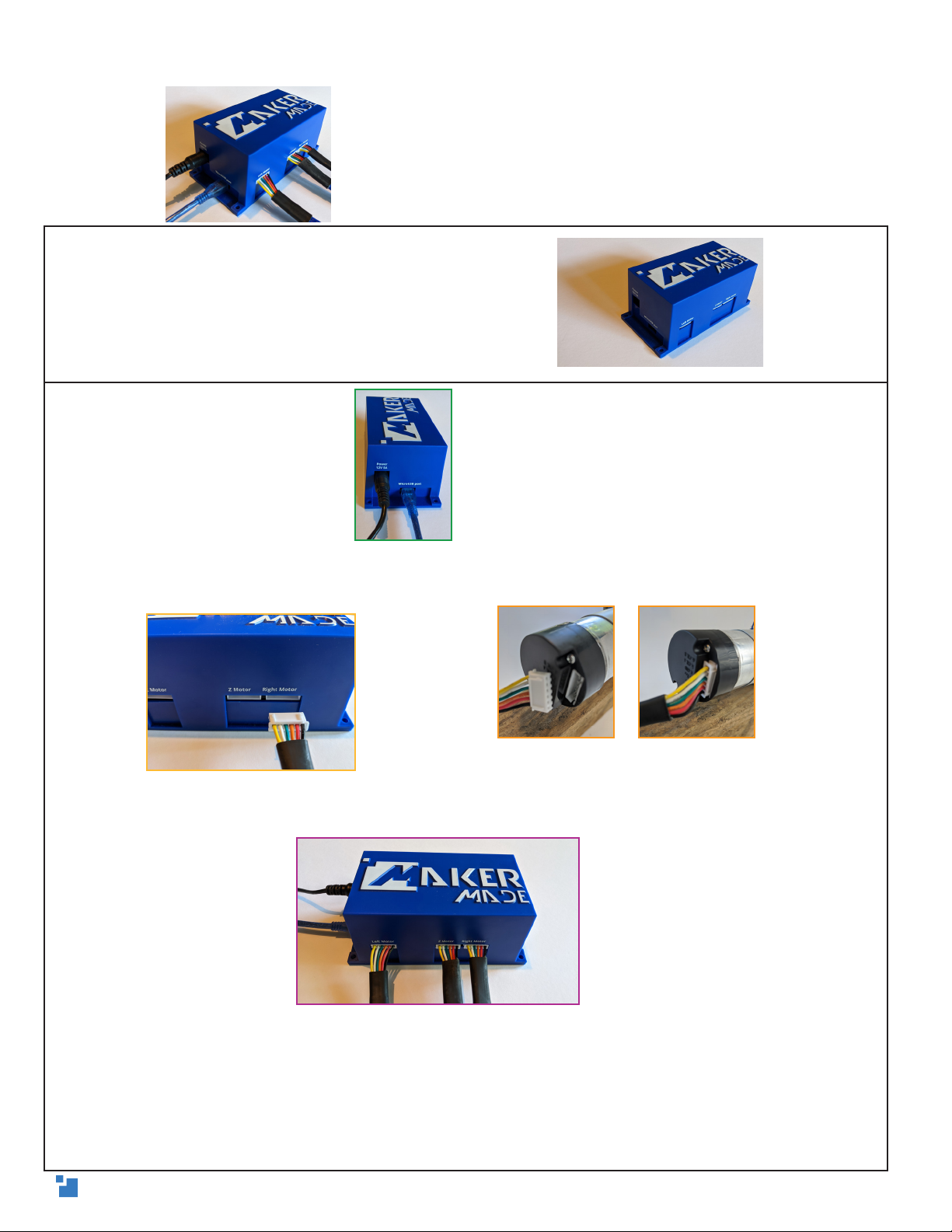
1. Mount the control board in its case to the wall above
your frame or behind the canvas. It helps to mount it in
the middle for the motor wires to reach everything.
2. (A) Plug in the USB, and power.
(B) The longer six-pin motor cables go to the X/Y motors, using the diagrams on the case. The
connections will only fit in one direction.
(C) The shorter blue cable is for the Z motor, and works best
to feed under the frame to the M2 on the front.
Drew’s Note: The M2’s brain is an Arduino DUE
microcontroller. We recommend mounting the DUE to
the wall behind your frame, but it can be mounted in
any safe location where it won’t be stepped on or in
conflict with the M2 during operation.
ARDUINO DUE board and shield
Drew’s Note: You can use the zip ties for cord maintenance! I also suggest putting a
drop of hot glue on the connections to ensure that they don’t wiggle loose over time.
If one of your motors of your M2 doesn’t move during operation, or the M2 generally
moves in a strange direction, the first thing to check are the motor connections. If the
wires connecting the X, Y, and Z motors are loose, even a tiny bit, it will cause your M2 to
malfunction.
Right/Left (X/Y) Motors
15

APPENDIX 1 - TIPS
The MakerMade M2 CNC kit is used to assemble a large format CNC machine. It is
designed to use a router (or another tool) to cut 4ft by 8ft sheet materials. When
used correctly, this machine is very safe. However, some safety precautions must
be taken to prevent injury. These include but are not limited to:
• Always follow the safety guidelines and instructions included with the router
or other tool you attach to the kit.
• Always wear ear and eye protection when running your machine.
• Use adequate dust collection or wear a respirator. Breathing material dust can
be harmful.
• Use proper lifting techniques when loading/unloading materials.
• Always use caution when connecting/removing the sled. This assembly weighs
around 20 lbs.
• NEVER leave your machine running unattended!
• Optionally, you can cut off the ends of the beams and the top of the vertical
frame legs outside of the stud mounts, so your frame isn’t as tall or long.
We’re excited to have you in our community of makers and can’t wait to see what
you create.
Find us on Facebook, Instagram and YouTube @makermadecnc and tag your
projects!
#MakerMadeMaker
Click here to check out updates on our FAQ section!
16
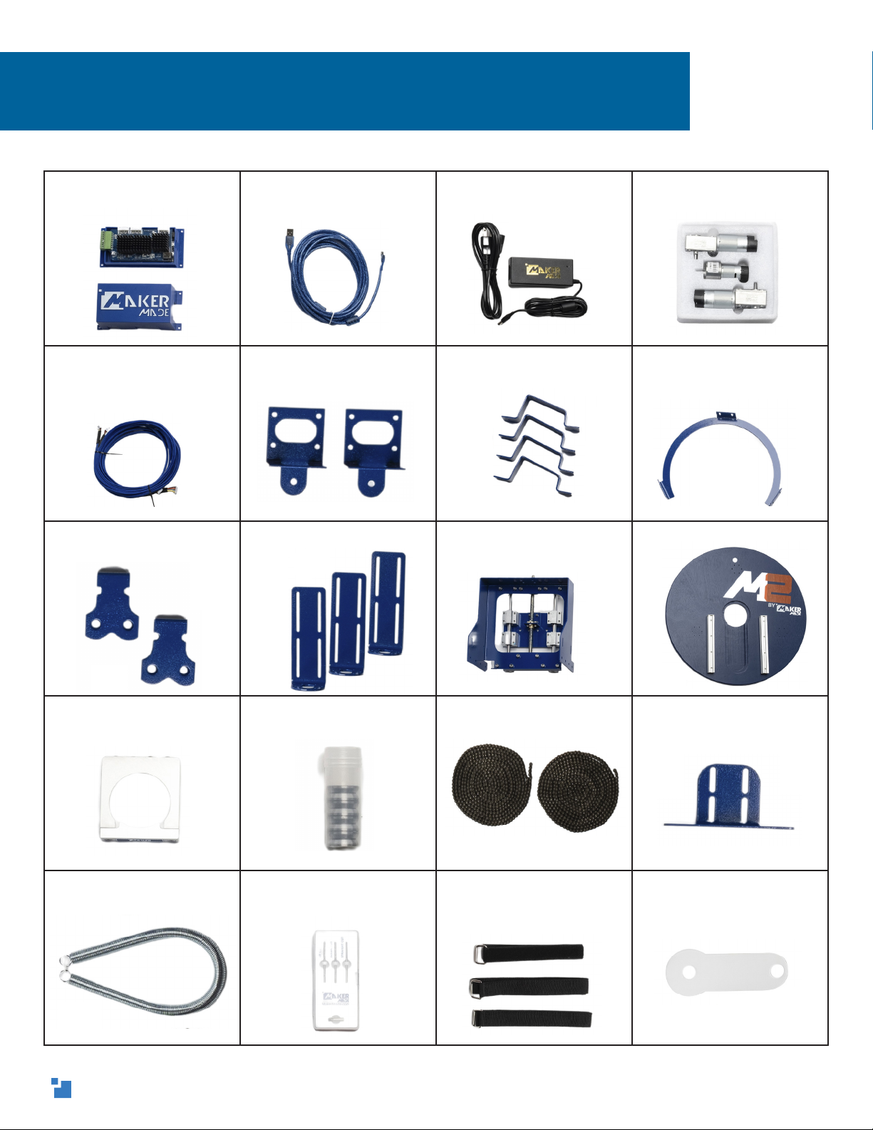
DUE v1.2 Control Board,
Shield, and case
10ft MicroUSB to USB cord AC/DC Power Adapter and
cord
X, Y, and Z Axis Motors (3)
X, Y, and Z Motor Power
Cables
Motor Mounting Brackets
(2)
Stud Mounts (4) Ring Carriage
Roller Bearing Carriages
(2)
Z-Axis Mount L-Brackets
(3)
Z-Axis Assembly Sled
Router Clamp Roller Bearings (4) Chains 335cm/11ft (2) Dust Collection Bracket
Spring Maker Made Router Bit
Starter Set
Velcro Dust Collection and
Brick Mounting Straps (3)
Acrylic Dust Cover
APPENDIX 2 - WHAT’S IN THE BOX?
17

Maker Made USB Marker Stickers, Quick Start
Guide, and Welcome
Letters
Chain Mounting Hardware
Bag A
Cotter pins (2)
Chain sprocket (2)
Small nails (2)
Large nails (2)
White spacers (2)
Spring Hardware Bag B
Quick links (2)
Small screws (4)
Zip ties
Short/Long Frame
Mounting Screws Bag C
Shorter black wood screws
Longer silver
Wood screws
Short/Long Frame
Mounting Screws Bag D
Shorter black wood
screws
Longer silver wood
screws
X/Y Motor Hardware Bag E
Motor sprocket (2)
Grub Screws (2)
Motor screws (8)
Motor washers (8)
Bearing Carriage
Hardware Bag F
Shoulder bolt (4)
Large washer (8)
Large locking nut (4)
Ring and L-Bracket
Hardware Bag G
Tiny wood screws (20)
Small black M3 bolts (12)
Locking nuts (12)
Assembly Tools Bag I
5mm hex wrench
4mm hex wrench
3mm hex wrench
Z Axis Hardware Bag C
Z Motor bracket
2.5mm and 2mm hex wrenches
Flat combo wrench
Belt Black M3 x 8mm bolts (6)
Large gear Small gear
Large set screws (2)
Small set screws (2)
M4 x 8mm bolts (4)
M4 Locking nuts (4)
M5 x 8mm bolts (8)
M5 T-nuts (8)
18

3ft (91cm)
wide
8ft
(2.4m)
tall
8.5ft (2.6m) long
APPENDIX 3 - OVERALL DIMENSIONS
It’s 6.5ft (1.98m) from the floor to the
top of the x/y motors, If the 8ft vertical
frame legs are cut down (optional).
10ft (3.05m)
long at the top
19

Visit our M2 Resources page for instructions over how to build the mini, standard, or XL
frames by MakerMade.
One of the amazing things about the M2 is the wide variety of frames that will work.
From all metal frames to using a weights in place of the spring- the options are almost
limitless!
However, there are four things to keep in mind when going rogue and building a unique
frame:
1. The bottom of your wasteboard should be at least 10” from the floor, so
the M2 has room to go across the bottom of your material.
2. For the trigonometry behind the M2’s movement, the wasteboard should
be clamped or screwed onto the stud mounts, to maintain a 15 degree
angle.
3. The target distance of the motor offset (from where the chain leaves the
motor sprockets to the top of the wasteboard) should be at least 18” for a
10ft top beam, 24” for 12ft top beam, and even higher to cut a larger area.
4. Your top beam and wasteboard must be level and equal distance from
each other.
5. Makerverse Calibration may be more difficult with frames not tested by
MakerMade.
Drew’s Note: Interested in coming up with your own frame design? Hop on our Facebook
Owner’s Group or Forum and discuss with other makers about your idea if someone has
made something similar!
APPENDIX 4 - CUSTOM FRAMES
Mini Frame:
6ft Top Beam
Smaller Chain
Cuts up to 4ft x 4ft
Standard Frame:
6ft Top Beam
11ft chains (included with M2)
Cuts up to 4ft x 8ft
XL Frame:
12ft Top Beam
15ft chains (purchased separately)
Cuts just over 4ft x 8ft
20
This manual suits for next models
1
Table of contents


