TE Connectivity 58075-1 User manual

©2011 Tyco Electronics Corporation, a TE Connectivity Ltd. Company
All Rights Reserved
*Trademark
TE Connectivity, TE connectivity (logo), and TE (logo) are trademarks. Other logos, product and/or Company names may be trademarks of their respective owners.
1of 5
Instruction Sheet
TOOLING ASSISTANCE CENTER
1-800-722-1111
PRODUCT INFORMATION
1-800-522-6752
This controlled document is subject to change.
For latest revision and Regional Customer Service,
visit our website at www.te.com LOC B
408-6789
Pistol Grip Pneumatic
Handle Assembly 58075-1 25 JUL 11 Rev E
PROPER USE GUIDELINES
Cumulative Trauma Disorders can result from the prolonged use of manually powered hand tools. Hand tools are intended for occasional use
and low volume applications. A wide selection of powered application equipment for extended-use, production operations is available.
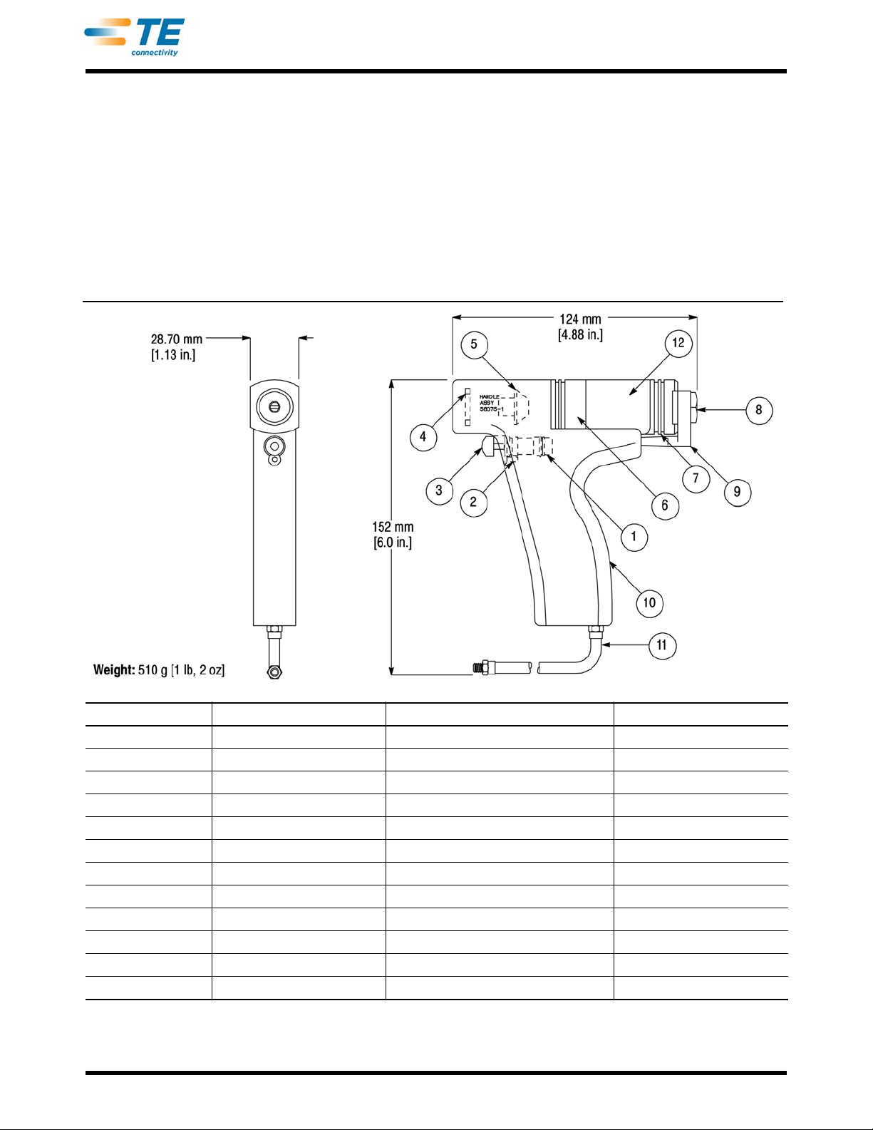
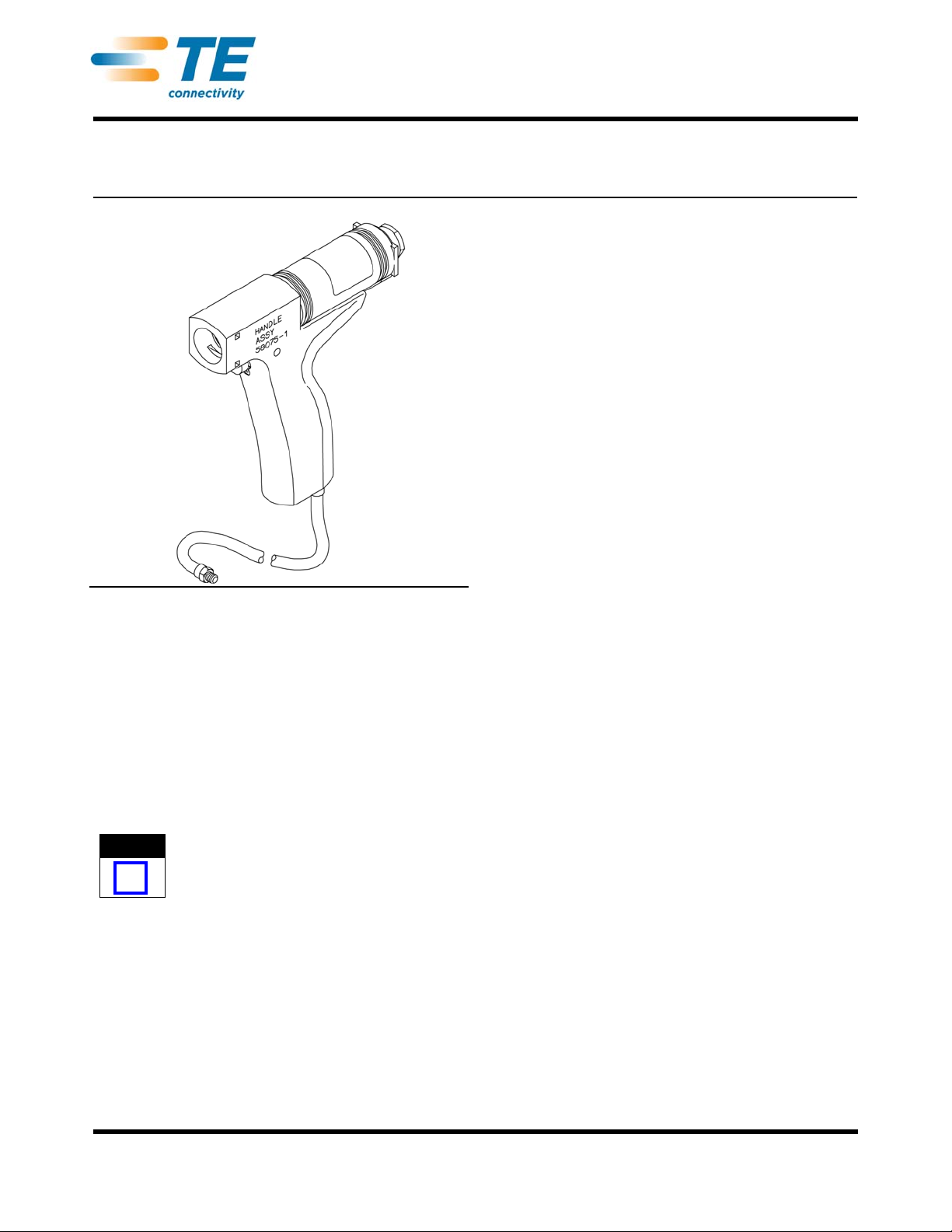
Figure 1
1. INTRODUCTION
These instructions deal with the safety, installation,
operation and maintenance of the Pistol Grip
Pneumatic Handle Assembly 58075-1. See Figure 1.
Pistol Grip Pneumatic Handle Assembly 58075-1
accepts interchangeable terminating heads that
terminate wires in connectors. To ensure accurate
termination of wires, setup adjustments, and head
maintenance, refer to the instructions packaged with
the terminating head.
NOTE
i
Dimensions in this instruction sheet are in metric
units [with U.S. customary units in brackets].
Figures are for reference onlyand are not drawn to
scale.
Reasons for reissue of this instruction sheet are
provided in Section 9, REVISION SUMMARY.
2. SAFETY PRECAUTIONS AND COMPANY CONTACT
2.1. Safety
Safeguards are designed into this application
equipment to protect operators and maintenance
personnel from most hazards during equipment
operation. However, certain safety precautions must
be taken by the operator and repair personnel to avoid
personal injury, as well as damage to the equipment.
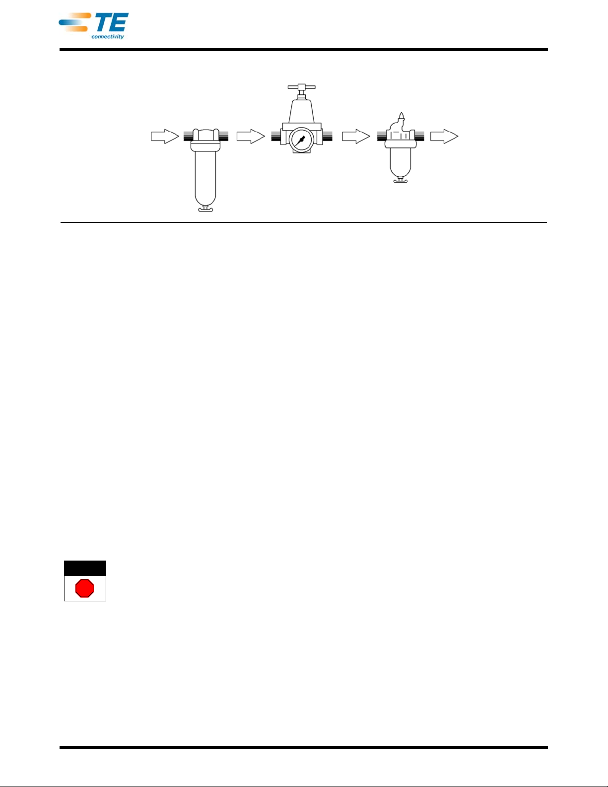
For best results, application equipment must be
operated in a dry, dust-free environment. Do not
operate equipment in a gaseous or hazardous
environment.
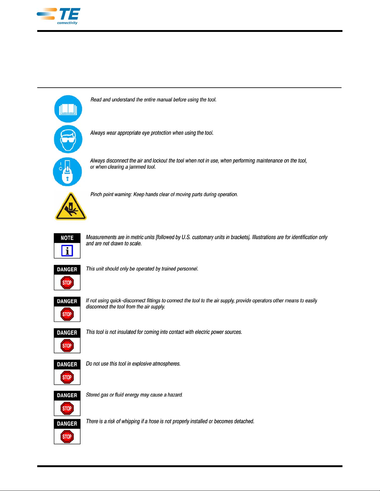
Carefully observe the following safety precautions
before and during operation of the equipment:
•ALWAYS wear appropriate ear protection.
•ALWAYS wear approved eye protection when
operating powered equipment.
•ALWAYS keep guard(s) in place during normal
operation.
•ALWAYS disconnect the tool from its power
source when performing maintenance on the
equipment.
•NEVER wear loose clothing or jewelry that may
catch in moving parts of the application equipment.
•NEVER insert hands into installed application
equipment.
•NEVER alter, modify, or misuse the application
equipment.
2.2. Contact
CALL TOLL FREE 1-800-722-1111 (CONTINENTAL
UNITED STATES AND PUERTO RICO ONLY)
The Tooling Assistance Center offers a means of
providing technical assistance when required.
In addition, Field Service Specialists are available to
provide assistance in the adjustment or repair of the
application equipment when problems arise which
your maintenance personnel are unable to correct.
When calling the Tooling Assistance Center regarding
service to equipment, it is suggested that a person
familiar with the device be present with a copy of the
manual (and drawings) to receive instructions. Many
difficulties can be avoided in this manner.
When calling the Tooling Assistance Center, be ready
with the following information:
1. Customer name
2. Customer address
3. Person to contact (name, title, telephone number,
and extension)
4. Person calling
ORIGINAL INSTRUCTIONS

408-6789
2of 5
Rev E
5. Equipment number (and serial number if
applicable)
6. Product part number (and serial number if
applicable)
7. Urgency of request
8. Nature of problem
9. Description of inoperative component(s)
10. Additional information/comments that may be
helpful

408-6789
3of 5
Rev E
Read these instructions thoroughly before operating
any of the pneumatic tools. The performance of these
tools will depend largely upon the intelligent use of
information contained in this manual and pay
particular attention to DANGER, CAUTION, and
NOTE statements.
DANGER
STOP
Denotes an imminent hazard which may result in
moderate or severe injury.
CAUTION
!
Denotes a condition which may result in product or
equipment damage.
NOTE
i
Highlights special or important information.
3. DESCRIPTION
The pneumatic handle assembly features a molded
nylon handle with a trigger and an air tube. The handle
holds an air cylinder with a key which retains the
terminating head in the body and allows the head to
be rotated. Refer to Figure 2.
In this use, the handle assembly noise level with the
terminating head emits a maximum of 78 dB, and the
vibration level is less than 2.5 mm/s².
Air Tube
Air Cylinder
Body
Key (Visible on
this Side)
Trigger
Handle
.
Figure 2
4. HEAD INSTALLATION AND REMOVAL
DANGER
STOP
To avoid personal injury, ALWAYS disconnect
handleassemblyfromtheairsupplywheninstalling
or removing the terminating head.
1. Disconnect and/or lockout the tool from its air
supply.
2. Position the blade tip of a screwdriver between
the shoulder of the key and the handle assembly
body. Pry and remove the key.
3. Insert the terminating head into the head
entrance until the head bottoms. See Figure 3.
Key
Terminating
Head (Ref)
Head Entrance
Figure 3
4. Re-insert the key to retain the head.
5. To remove the head, remove the key and pull the
head out of the handle assembly.
5. SETUP
It is recommended that a regulator-filter-lubricator unit
with the lubricator adjusted to the minimum setting be
used with the handle assembly. Refer to Figure 4.
It is also recommended that quick-disconnect fittings
are used to connect the tool to the air supply. If not
using quick-disconnect fittings, provide a pneumatic
lock-out on the air line that bleeds air after it is turned
off.
The handle assembly is designed to operate with an
air pressure range of 276 to 483 kPa [40 to 70 psi].
Service life can be greatly extended when only the
necessary air pressure is applied. Excessive pressure
causes wear and strain on handle assembly
components and the connectors.
CAUTION
!
Do not use this tool as a blunt object, a crushing
device, or for any purpose other than crimping the
proper specified product. Inappropriate use of the
toolcould result in personal injuryordamagetothe
tool.

To Machine
Lubricator
Regulator
Filter and Moisture
Separator
Airflow
408-6789
4of 5
Rev E
Figure 4
6. OPERATION
The following procedure provides only general
information concerning crimping. Refer to the
instructions packaged with the terminating heads for
detailed information including wire stripping
dimensions and instructions for positioning terminals
in the terminating heads.
1. Insert the connector into the left side of the head.
2. Align the contact to be terminated with the wire
inserter of the head. Make sure that the locating
pawl rests between the connector index ribs.
3. Insert an unstripped wire into the funnel area
between the contact and the wire inserter until it
bottoms on the tool base.
4. Depress the trigger of the handle assembly and
hold it until the wire inserter bottoms.
5. Release the trigger. The wire inserter will retract
and the feed slide will automatically advance the
connector to the next contact position.
6. Repeat steps 2 through 5 until all contacts have
been terminated.
7. Inspect each termination.
7. MAINTENANCE AND INSPECTION
DANGER
STOP
To avoid personal injury, ALWAYS disconnect the
handle assembly from the air supply when
performing maintenance or inspection procedures.
It is recommended that a maintenance and inspection
program be performed periodically to ensure
dependable and uniform terminations. Though
recommendations call for at least one inspection a
month, frequency of inspection depends on:
1. The care, amount of use, and handling of the
handle assembly.
2. The presence of abnormal amounts of dust and
dirt.
3. The degree of operator skill.
4. Your own established standards.
The handle assembly is inspected before being
shipped; however, it is recommended that the handle
assembly be inspected immediately upon arrival to
ensure that the handle assembly has not been
damaged during shipment.
7.1. Daily Maintenance
Each operator should be aware of, and responsible
for, the following:
1. Remove dust, moisture, and other contaminants
with a clean brush, or soft, lint-free cloth. DO NOT
use objects that could damage the handle
assembly.
2. Ensure that all components are in place and
properly secured.
3. With the terminating head in place, connect the
air supply, then squeeze and release the trigger to
ensure that the mechanisms and plunger move
smoothly.
7.2. Periodic Inspection (At Least Once a Month)
1. Remove any accumulated film with a suitable
cleaning agent that will not affect plastic material.
2. Make sure all components are in place and are
properly secured. Refer to Figure 5. Check the
handle assembly for chipped, cracked, worn, or
broken areas. If damage is evident, repair is
necessary. See Section 8, REPLACEMENT AND
REPAIR.
8. REPLACEMENT AND REPAIR
Customer-replaceable parts are listed in Figure 5.
A complete inventory can be stocked and controlled to
prevent lost time when replacement of parts is
necessary. Parts other than those listed should be
replaced by TE to ensure quality and reliability of the
handle assembly. Order replacement parts through

408-6789
5of 5
Rev E
your representative, or call 1-800-526-5142, or send a
facsimile of your purchase to 717-986-7605, or write
to:
CUSTOMER SERVICE (038-035)
TYCO ELECTRONICS CORPORATION
PO BOX 3608
HARRISBURG PA 17105-3608
or
TYCO ELECTRONICS CORPORATION UK LTD
BARTON TORS
BIDEFORD
NORTH DEVON, GREAT BRITAIN
For customer repair service, call 1-800-526-5136.
9. REVISION SUMMARY
Since the previous release of these instructions, the
new company logo was applied, and the document
was re-formatted and re-arranged.
ITEM PART NUMBER DESCRIPTION QTY PER ASSEMBLY
127174-1 VALVE, Poppet 1
21-21003-3 SCREW, Flat Head Socket Cap 1
328472-1 PUSH BUTTON TRIGGER, Valve Actuator 1
4312140-1 KEY 1
5312141-1 NUT, Cam Adjustment 1
6312157-1 AIR CYLINDER 1
721086-6 O-RING 2
8310421-1 PLUG, Cap 1
9310424-1 BRACKET, Air Cylinder 1
10 312156-1 HANDLE 1
11 312622-2 SUBASSEMBLY, Air Tube 1
12 217915-1 LABEL, CE 1
Figure 5
Table of contents
Other TE Connectivity Power Tools Accessories manuals
Popular Power Tools Accessories manuals by other brands

Meler
Meler Arion Installation & technical guide

Echo
Echo Speed-Feed Universal 400 LH/RH Installation and loading instructions

Atlas Copco
Atlas Copco BBD 46WS-6 Safety and operating instructions

sauter
sauter OFL1.0 manual

Spearhead
Spearhead Trisaw Series Operator's instruction manual

AEG
AEG OMNI-RT Original instructions