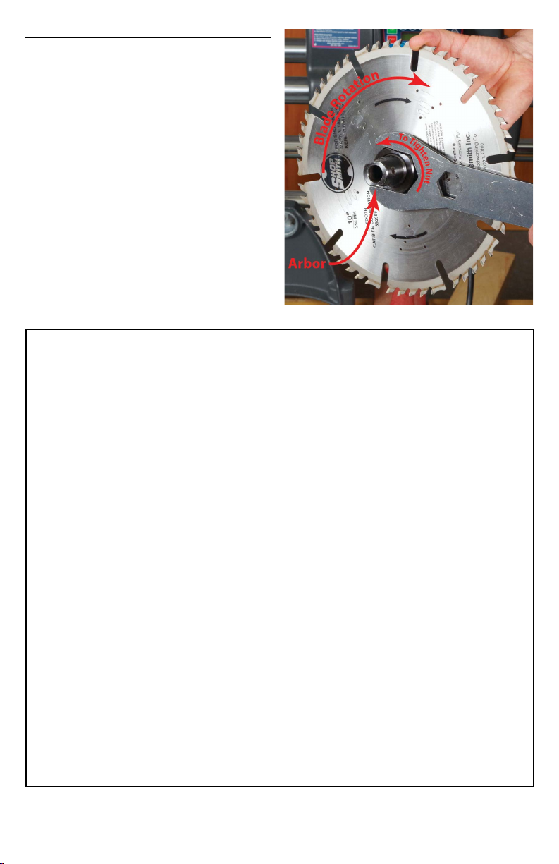
Reverse-Threaded Spindles
Reverse threaded spindles are common on some
types of power tools. “Reverse threaded” just
means that the torque of the motor in normal
operation puts force on the arbor nut to tighten
the “business end” onto the spindle. This is an
inherent safety measure in all power tools and
helps to make sure that cutting blades and
sanding/grinding surfaces don’t loosen during
normal operation.
When a motor brake is used to slow a machine’s
operation, the momentum of the “business end”
puts a loosening force onto the arbor nut. If this
force is sufficiently large, it can loosen or
unscrew the arbor nut. For this reason, you never
want to apply excessive braking torque to a
reverse threaded spindle. To prevent excessive
braking torque on reverse-threaded arbor tools,
adhere to the following operational limitations.
Limitations of Operation
If you have a machine with a reverse threaded spindle, ensure that you follow the rules and
limitations below. Failure to follow the limitations below may increase risk of injury.
1. Check tightness of arbor nut prior to
installation and as a regular
maintenance item.
Regularly check the tightness of your arbor
nut and compare to the listed torque
specifications in your tool manual. To
prevent loosening, use double-nuts or other
positive locking methods.
2. Calibrate braking torque to bring the tool
to stop in no less than two seconds.
When braking a tool with a reverse-threaded
spindle, never calibrate the brake to stop the
tool in less than two seconds. Refer to the
calibration section of this manual for a
discussion of how to calibrate your device.
3. Never use The MAKESafe Power Tool
Brake to brake high inertia
reverse-threaded loads, such as:
○ a lathe with a reverse-threaded
spindle.
○ A saw with a dado or other
non-standard blade installed.
The larger the business end, the more
loosening force will be applied during
braking. For example, a lathe with a
reverse-threaded spindle should never be
used with a motor brake. The chuck has
sufficient mass to unscrew itself from the
spindle during braking and is a severe
safety risk.
4. Always make sure that all power tool
wheel guards, blade guards, shields,
and other manufacturer-provided and
OSHA required guards are properly
installed and adjusted.
Power tools should never be operated
without manufacturer-provided and OSHA
required guards.
MAKESafe Tools, Inc. | Copyright 2021 | Last Updated 12/29/21 Page 7