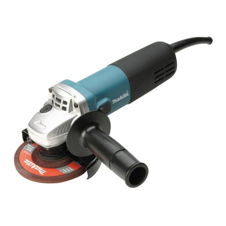
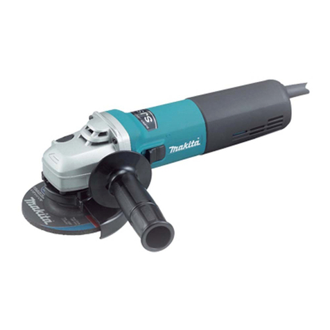
Makita 9047 User manual

GB
Angle Grinder Instruction Manual
F
Meuleuse d’Angle Manuel d’Instructions
D
Winkelschleifer Betriebsanleitung
I
Smerigliatrice Angolare Istruzioni d’Uso
NL
Haakse slijpmachine Gebruiksaanwijzing
E
Amoladora Manual de Instrucciones
P
Rebarbadora Manual de Instruço˜es
DK
Vinkelsliber Brugsanvisning
S
Vinkelslipmaskin Bruksanvisning
N
Vinkelsliper Bruksanvisning
SF
Kulmahiomakone Käyttöohje
GR °ˆÓÈ·Îfi˜ §ÂÈ·ÓÙ‹Ú·˜ √‰ËÁ›Â˜ ÃÚ‹Ûˆ˜
TR Kös¸e Bileyici El kitabı
180 mm (7’’) 9047/9047S
180 mm (7’’) 9057/9057S
230 mm (9’’) 9049/9049S
230 mm (9’’) 9059/9059S
9047F/9047SF
9057F/9057SF
9049F/9049SF
9059F/9059SF
9047(cover) (’100. 10. 11)

1 2
34
5 6
7
15°– 30°
2
9047 (illust) (’100. 10. 11)

Symbols
The following show the symbols used for the tool. Be sure that you understand their meaning before use.
Symboles
Nous donnons ci-dessous les symboles utilisés pour l’outil. Assurez-vous que vous en avez bien compris la
signification avant d’utiliser l’outil.
Symbole
Die folgenden Symbole werden für die Maschine verwendet. Machen Sie sich vor der Benutzung unbedingt mit
ihrer Bedeutung vertraut.
Symboli
Per questo utensile vengono usati i simboli seguenti. Bisogna capire il loro significato prima di usare l’utensile.
Symbolen
Voor dit gereedschap worden de volgende symbolen gebruikt. Zorg ervoor dat u de betekenis van deze
symbolen begrijpt alvorens het gereedschap te gebruiken.
Símbolos
A continuación se muestran los símbolos utilizados con esta herramienta. Asegúrese de que entiende su
significado antes de usarla.
Símbolos
O seguinte mostra os símbolos utilizados para a ferramenta. Certifique-se de que compreende o seu
significado antes da utilização.
Symboler
Nedenstående symboler er anvendt i forbindelse med denne maskine. Vær sikker på, at De har forstået
symbolernes betydning, før maskinen anvendes.
Symboler
Det följande visar de symboler som används för den här maskinen. Se noga till att du förstår deras innebörd
innan maskinen används.
Symbolene
Følgende viser de symblene som brukes for maskinen. Det er viktig å forstå betydningen av disse før maskinen
tas i bruk.
Symbolit
Alla on esitetty koneessa käytetyt symbolit. Opettele näiden merkitys, ennen kuin käytät konetta.
™‡Ì‚ÔÏ·
∆· ·ÎfiÏÔ˘ı· ‰Â›¯ÓÔ˘Ó Ù· ۇ̂ÔÏ· Ô˘ ¯ÚËÛÈÌÔÔÈÔ‡ÓÙ·È ÁÈ· ÙÔ Ì˯¿ÓËÌ·. µÂ‚·Èˆı›Ù fiÙÈ
ηٷϷ‚·›ÓÂÙ ÙË ÛËÌ·Û›· ÙÔ˘˜ ÚÈÓ ·fi ÙË ¯Ú‹ÛË.
Semboller
As¸ag˘¶dakiler makinan¶z i≥in kullan¶lan sembolleri göstermektedir. Kullanmadan önce manalar¶n¶ anlad¶g˘¶n¶zdan emin
olunuz.
[Read instruction manual.
[Lire le mode d’emploi.
[Bitte Bedienungsanleitung lesen.
[Leggete il manuale di istruzioni.
[Lees de gebruiksaanwijzing.
[Lea el manual de instrucciones.
[Leia o manual de instruço˜es.
[Læs brugsanvisningen.
[Läs bruksanvisningen.
[Les bruksanvisingen.
[Katso käyttöohjeita.
[¢È·‚¿ÛÙ ÙȘ Ô‰ËÁ›Â˜ ¯Ú‹Û˘.
[El kitab¶n¶ okuyun.
[DOUBLE INSULATION
[DOUBLE ISOLATION
[DOPPELT SCHUTZISOLIERT
[DOPPIO ISOLAMENTO
[DUBBELE ISOLATIE
[DOBLE AISLAMIENTO
[DUPLO ISOLAMENTO
[DOBBELT ISOLATION
[DUBBEL ISOLERING
[DOBBEL ISOLERING
[KAKSINKERTAINEN ERISTYS
[¢π¶§∏ ª√¡ø™∏
[˘I~FT YALITIMLI
9047 (illust) (’100. 10. 11)
3

ENGLISH Explanation of general view
1Wheel guard
2Screw
3Notch
4Side grip
5Lock nut
6Depressed center wheel
7Inner flange
8Super flange
9Lock nut wrench
0Shaft lock
qSwitch trigger
wLock lever
eBrush holder cap
rScrewdriver
SPECIFICATIONS
Model 9047/9047S 9057/9057S 9049/9049S 9059/9059S
9047F/9047SF 9057F/9057SF 9049F/9049SF 9059F/9059SF
Depressed center wheel diameter ........................ 180 mm 180 mm 230 mm 230 mm
No load speed (RPM) ........................................... 8,500 8,500 6,600 6,600
Overall length ........................................................ 470 mm 470 mm 470 mm 470 mm
Net weight ............................................................. 4.8 kg 5.1 kg 4.8 kg 5.1 kg
•Due to the continuing program of research and
development, the specifications herein are subject
to change without prior notice.
•Note: Specifications may differ from country to
country.
Power supply
The tool should be connected only to a power supply
of the same voltage as indicated on the nameplate,
and can only be operated on single-phaseAC supply.
They are double-insulated in accordance with Euro-
pean Standard and can, therefore, also be used from
sockets without earth wire.
For models 9047, 9049, 9057 and 9059, public
low-voltage distribution systems of between
220 V and 250 V
Switching operations of electric apparatus cause volt-
age fluctuations. The operation of this device under
unfavorable mains conditions can have adverse
effects to the operation of other equipment. With a
mains impedance equal or less than 0.22 (for 9047
and 9049) / 0.24 (for 9057 and 9059) Ohms it can be
presumed that there will be no negative effects.
The mains socket used for this device must be
protected with a fuse or protective circuit breaker
having slow tripping characteristics.
Safety hints
For your own safety, please refer to enclosed safety
instructions.
ADDITIONAL SAFETY RULES
1. Always be sure that the tool is switched off
and unplugged before carrying out any work
on the tool.
2. Keep guards in place.
3. Use only wheels having a maximum operating
speed at least as high as ‘‘No Load RPM’’
marked on the tool’s nameplate.
When using depressed center wheels, be sure
to use only fiberglass-reinforced wheels.
4. Check the wheel carefully for cracks or dam-
age before operation. Replace cracked or
damaged wheel immediately.
5. Use only flanges specified for this tool.
6. Do not damage the spindle, the flange (espe-
cially the installing surface) or the lock nut.
Damage to these parts could result in wheel
breakage.
7. Keep hands away from rotating parts.
8. Make sure the wheel is not contacting the
workpiece before the switch is turned on.
9. Before using the tool on an actual workpiece,
let it run for a while. Watch for vibration or
wobbling that could indicate poor installation
or a poorly balanced wheel.
10. Use the specified surface of the wheel to
perform the grinding.
11. Watch out for flying sparks. Hold the tool so
that sparks fly away from you and other per-
sons or flammable materials.
12. Do not touch the workpiece immediately after
operation; it may be extremely hot and could
burn your skin.
13. Always wear safety goggles and ear protec-
tors during operation.
14. Position the tool so that the power cord
always stays behind the tool during operation.
15. If working place is extremely hot and humid, or
badly polluted by conductive dust, use a
short-circuit breaker (30 mA) to assure opera-
tor safety.
16. Do not use the tool on any materials contain-
ing asbestos.
SAVE THESE INSTRUCTIONS.
OPERATING INSTRUCTIONS
Installing wheel guard (Fig. 1)
When installing a depressed center wheel or an
abrasive cut-off wheel, always use a wheel guard.
Mount the wheel guard with the tab on the wheel
guard band aligned with the notch on the bearing box.
Then rotate the wheel guard 160 degrees counter-
clockwise. Be sure to tighten the screw securely.
4
9047(E) (’100. 10. 11)

Installing side grip (auxiliary handle) (Fig. 2)
Always install the side grip on the tool securely before
operation. The side grip can be installed in any of
three positions on the sides of the tool, whichever is
convenient and keeps the guard properly positioned.
Always hold the tool’s switch handle and the side grip
firmly with both hands during operation.
Installing or removing depressed center
wheel (Fig.3&4)
Important:
Always be sure that the tool is switched off and
unplugged before installing or removing the wheel.
Mount the inner flange onto the spindle. Fit the wheel
on over the inner flange and screw the lock nut onto
the spindle.
To tighten the lock nut, press the shaft lock firmly so
that the spindle cannot revolve, then use the lock nut
wrench and securely tighten clockwise.
To remove the wheel, follow the installation procedure
in reverse.
NOTE:
Super flange
Models 9047F, 9057F, 9049F, 9059F, 9047SF,
9057SF, 9049SF and 9059SF are standard-equipped
with a super flange.
Only 1/3 of efforts needed to undo lock nut, compared
with conventional type.
Switch action (Fig. 5)
CAUTION:
Before plugging the tool, always check to see that the
switch trigger actuates properly and returns to the
‘‘OFF’’ position when released.
For U.K., Australia, France and Algeria
To prevent the trigger from being accidentally actu-
ated, a lock lever is provided. To start the tool, push
the lock lever in and then pull the trigger. Release the
trigger to stop.
For Germany, Austria, Italy, Netherlands, Belgium,
Spain, Portugal, Denmark, Sweden, Norway,
Finland and Greece
To prevent the trigger from being accidentally actu-
ated, a lock lever is provided. To start the tool, push
the lock lever in and then pull the trigger. Release the
trigger to stop. For continuous operation, push the
lock lever in, pull the trigger and then push the lock
lever further in. To stop the tool from the locked
position, pull the trigger fully, then release it.
For other countries than the above countries
To start the tool, simply pull the trigger. Release the
trigger to stop. For continuous operation, pull the
trigger and then push the lock lever. To stop the tool
from the locked position, pull the trigger fully, then
release it.
NOTE:
Models 9047S, 9057S, 9049S, 9059S, 9047SF,
9057SF, 9049SF and 9059SF begin to run slowly
when they are turned on. This soft start feature
assures smoother operation and less operator
fatigue.
Operation (Fig. 6)
Hold the tool firmly. Turn the tool on and then apply
the wheel or disc to the workpiece.
In general, keep the edge of the wheel or disc at an
angle of about 15° – 30° to the workpiece surface.
During the break-in period with a new wheel, do not
work the tool in the B direction or it will cut into the
workpiece. Once the edge of the wheel has been
rounded off by use, the wheel may be worked in both
A and B directions.
WARNING:
•It should never be necessary to force the tool. The
weight of the tool applies adequate pressure. Forc-
ing and excessive pressure could cause dangerous
wheel breakage.
•Continued use of a worn-out wheel may result in
wheel explosion and serious personal injury.
Depressed center wheel should not be used after it
has been worn down to 115 mm in diameter. Use of
the wheel after this point is unsafe and it should be
removed from service and rendered unusable by
intentional destruction.
MAINTENANCE
CAUTION:
Always be sure that the tool is switched off and
unplugged before carrying out any work on the tool.
Replacement of carbon brushes (Fig. 7)
Whenever carbon brushes must be replaced, they cut
out the tool automatically. When this occurs, replace
the carbon brushes at the same time. Use only
identical carbon brushes.
To maintain product safety and reliability, repairs,
maintenance or adjustment should be carried out by
Makita Authorized Service Center.
9047(E) (’100. 10. 11)
5
Other manuals for 9047
1
This manual suits for next models
15
Table of contents
Languages:
Other Makita Grinder manuals

Makita
Makita 9005B User manual

Makita
Makita GA5000 User manual

Makita
Makita GA7020R User manual

Makita
Makita GD0601 User manual

Makita
Makita DGA408 User manual

Makita
Makita GD0600 User manual

Makita
Makita GAG03 User manual

Makita
Makita GA037G User manual

Makita
Makita 9218SB Quick start guide

Makita
Makita DGA402 User manual

Makita
Makita GA7070 User manual

Makita
Makita GA5030R User manual

Makita
Makita 9561CR User manual

Makita
Makita 906H Quick start guide

Makita
Makita GA5011 Manual

Makita
Makita 9555NBK User manual

Makita
Makita GA9063 User manual

Makita
Makita GA9063RX02 User manual

Makita
Makita GD0602 User manual

Makita
Makita DGA406 User manual