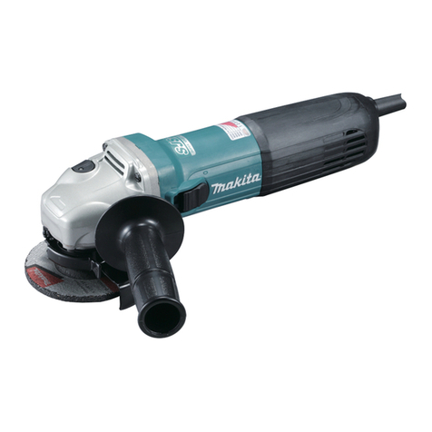
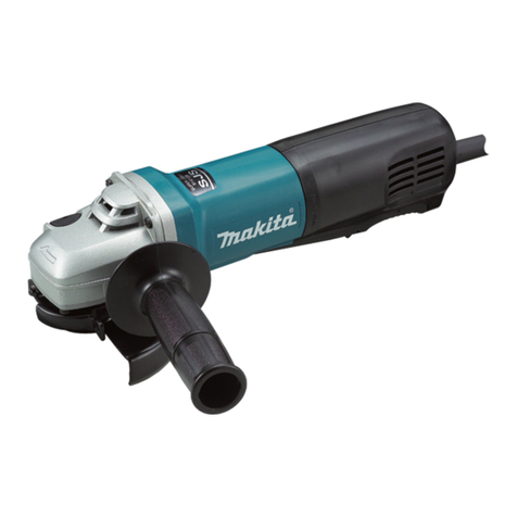
Makita 9556HN User manual

Angle Grinder INSTRUCTION MANUAL
Kotni brusilnik NAVODILO ZA UPORABO
Lëmues këndesh MANUALI I PËRDORIMIT
Ъглошлайф
РЪКОВОДСТВО ЗА ЕКСПЛОАТАЦИЯ
Kutna brusilica PRIRUČNIK S UPUTAMA
Аголна брусилка УПАТСТВО ЗА УПОТРЕБА
Polizor unghiular MANUAL DE INSTRUCŢIUNI
Угаона брусилица УПУТСТВО ЗА УПОТРЕБУ
Угловая шлифмашина
РУКОВОДСТВО ПО ЭКСПЛУАТАЦИИ
Кутова шліфувальна машина ІНСТРУКЦІЯ З ЕКСПЛУАТАЦІЇ
9556HN
9557HN
9558HN
GB
SI
AL
BG
HR
MK
RO
RS
RUS
UA

2
1
005802
2 005803
3 005804
4
009057
5
009062
6
001070
7
005917
8
008383
9
005831
10
014103
11
010855
12
005809
1
2
1
2
3
4
1
15
A
B
1
2
3
1
2
1
2
3
1
3
2
1
3
2
1
1

3
ENGLISH (Original instructions)
Explanation of general view
1-1.Shaftlock
2-1. Switch lever
4-1. Wheel guard
4-2. Screw
4-3. Bearing box
5-1. Wheel guard
5-2. Bearing box
5-3. Screw
6-1.Locknut
6-2. Depressed center grinding
wheel/Multi-disc
6-3. Inner flange
7-1. Lock nut wrench
7-2.Shaftlock
8-1.Locknut
8-2.Abrasive disc
8-3. Rubber pad
10-1. Wire cup brush/Wire bevel brush
11-1.Locknut
11-2.Abrasive cut-off wheel/diamond
wheel
11-3. Inner flange
11-4. Wheel guard for abrasive cut-off
wheel/diamondwheel
12-1.Exhaust vent
12-2.Inhalation vent
SPECIFICATIONS
Model
9556HN
9557HN
9558HN
Depressed center wheel diameter
100 mm
115 mm
125 mm
Max. wheel thickness
6.4 mm
6.4 mm
6.4 mm
Spindle thread
M10
M14 or 5/8"
(country specific)
M14 or 5/8"
(country specific)
Rated speed (n) / No load speed (no)
11,000 min-1
11,000 min-1
11,000 min-1
Overall length
271 mm
271 mm
271 mm
Net weight
1.9 kg
2.0 kg
2.1 kg
Safety class
/II
•Due to our continuing program of research and development, the specifications herein are subject to change without notice.
•Specifications may differ from country to country.
•Weight according to EPTA-Procedure 01/2003
Intended use ENE048-1 Model 9557HN
The tool is intended for grinding, sanding and cutting of
metal and stone materials without the use of water.
ENF002-2
Power supply
The tool should be connected only to a power supply of
the same voltage as indicated on the nameplate, and
Work mode : surface grinding
Vibration emission (ah,AG) : 7.5 m/s2
Uncertainty (K) : 1.5 m/s2
Work mode: disc sanding
can only be operated on single-phase AC supply. They Vibration emission (ah,DS) : 2.5 m/s2 or less
2
are double-insulated and can, therefore, also be used
from sockets without earth wire.
ENG905-1
Noise
The typical A-weighted noise level determined
according to EN60745:
Model 9557HN, 9558HN
Uncertainty (K) : 1.5 m/s
Model 9558HN
Work mode : surface grinding
Vibration emission (ah,AG) : 8.5 m/s2
Uncertainty (K) : 1.5 m/s2
Work mode: disc sanding
Sound pressure level (LpA) : 86 dB (A) Vibration emission (ah,DS) : 2.5 m/s2 or less
2
Sound power level (LWA) : 97 dB (A) Uncertainty (K) : 1.5 m/s ENG902-1
Uncertainty (K) : 3 dB (A)
Wear ear protection
Vibration
ENG900-1
•
The declared vibration emission value has been
measured in accordance with the standard test
method and may be used for comparing one tool
with another.
•
The declared vibration emission value may also be
The vibration total value (tri-axial vector sum)
determined according to EN60745: used in a preliminary assessment of exposure.
•
The declared vibration emission value is used for
main applications of the power tool. However if the
power tool is used for other applications, the
vibration emission value may be different.

4
WARNING:
•
The vibration emission during actual use of the
power tool can differ from the declared emission
value depending on the ways in which the tool is
used.
•
Be sure to identify safety measures to protect the
operator that are based on an estimation of
exposure in the actual conditions of use (taking
account of all parts of the operating cycle such as
the times when the tool is switched off and when it
is running idle in addition to the trigger time).
ENH101-16
For European countries only
EC Declaration of Conformity
We Makita Corporation as the responsible
manufacturer declare that the following Makita
machine(s):
Designation of Machine:
Angle Grinder
Model No./ Type: 9557HN,9558HN
are of series production and
Conforms to the following European Directives:
2006/42/EC, 2004/108/EC
And are manufactured in accordance with the following
standards or standardised documents:
EN60745
The technical documentation is kept by:
Makita International Europe Ltd.
Technical Department,
Michigan Drive, Tongwell,
Milton Keynes, Bucks MK15 8JD, England
30.1.2009
000230 Tomoyasu Kato
Director
Makita Corporation
3-11-8, Sumiyoshi-cho,
Anjo, Aichi, 446-8502, JAPAN
GEA010-1
General Power Tool Safety
Warnings
WARNING Read all safety warnings and all
instructions. Failure to follow the warnings and
instructions may result in electric shock, fire and/or
serious injury.
Save all warnings and instructions for
future reference.
GEB033-7
GRINDER SAFETY WARNINGS
Safety Warnings Common for Grinding, Sanding,
Wire Brushing, or Abrasive Cutting-Off Operations:
1. This power tool is intended to function as a
grinder, sander, wire brush or cut-off tool.
Read all safety warnings, instructions,
illustrations and specifications provided with
this power tool. Failure to follow all instructions
listed below may result in electric shock, fire
and/or serious injury.
2. Operations such as polishing are not
recommended to be performed with this
power tool. Operations for which the power tool
was not designed may create a hazard and cause
personal injury.
3. Do not use accessories which are not
specifically designed and recommended by
the tool manufacturer. Just because the
accessory can be attached to your power tool, it
does not assure safe operation.
4. The rated speed of the accessory must be at
least equal to the maximum speed marked on
the power tool. Accessories running faster than
their rated speed can break and fly apart.
5. The outside diameter and the thickness of
your accessory must be within the capacity
rating of your power tool. Incorrectly sized
accessories cannot be adequately guarded or
controlled.
6. Threaded mounting of accessories must
match the grinder spindle thread. For
accessories mounted by flanges, the arbour
hole of the accessory must fit the locating
diameter of the flange. Accessories that do not
match the mounting hardware of the power tool
will run out of balance, vibrate excessively and
may cause loss of control.
7. Do not use a damaged accessory. Before each
use inspect the accessory such as abrasive
wheels for chips and cracks, backing pad for
cracks, tear or excess wear, wire brush for
loose or cracked wires. If power tool or
accessory is dropped, inspect for damage or
install an undamaged accessory. After
inspecting and installing an accessory,
position yourself and bystanders away from
the plane of the rotating accessory and run
the power tool at maximum no-load speed for
one minute. Damaged accessories will normally
break apart during this test time.
8. Wear personal protective equipment.
Depending on application, use face shield,
safety goggles or safety glasses. As
appropriate, wear dust mask, hearing
protectors, gloves and workshop apron
capable of stopping small abrasive or

5
workpiece fragments. The eye protection must
be capable of stopping flying debris generated by
various operations. The dust mask or respirator
must be capable of filtrating particles generated
by your operation. Prolonged exposure to high
intensity noise may cause hearing loss.
9. Keep bystanders a safe distance away from
work area. Anyone entering the work area
must wear personal protective equipment.
Fragments of workpiece or of a broken accessory
may fly away and cause injury beyond immediate
area of operation.
10. Hold the power tool by insulated gripping
surfaces only, when performing an operation
where the cutting accessory may contact
hidden wiring or its own cord. Cutting
accessory contacting a "live" wire may make
exposed metal parts of the power tool "live" and
could give the operator an electric shock.
11. Position the cord clear of the spinning
accessory. If you lose control, the cord may be
cut or snagged and your hand or arm may be
pulled into the spinning accessory.
12. Never lay the power tool down until the
accessory has come to a complete stop. The
spinning accessory may grab the surface and pull
the power tool out of your control.
13. Do not run the power tool while carrying it at
your side. Accidental contact with the spinning
accessory could snag your clothing, pulling the
accessory into your body.
14. Regularly clean the power tool’s air vents. The
motor’s fan will draw the dust inside the housing
and excessive accumulation of powdered metal
may cause electrical hazards.
15. Do not operate the power tool near flammable
materials. Sparks could ignite these materials.
16. Do not use accessories that require liquid
coolants. Using water or other liquid coolants
may result in electrocution or shock.
Kickback and Related Warnings
Kickback is a sudden reaction to a pinched or snagged
rotatingwheel,backingpad,brushoranyotheraccessory.
Pinching or snagging causes rapid stalling of the rotating
accessory which in turn causes the uncontrolled power
tool to be forced in the direction opposite of the
accessory’s rotationatthepointofthebinding.
For example, if an abrasive wheel is snagged or
pinched by the workpiece, the edge of the wheel that is
entering into the pinch point can dig into the surface of
the material causing the wheel to climb out or kick out.
The wheel may either jump toward or away from the
operator, depending on direction of the wheel’s
movement at the point of pinching. Abrasive wheels
may also break under these conditions.
Kickback is the result of power tool misuse and/or
incorrect operating procedures or conditions and can be
avoided by taking proper precautions as given below.
a) Maintain a firm grip on the power tool and
position your body and arm to allow you to
resist kickback forces. Always use auxiliary
handle, if provided, for maximum control over
kickback or torque reaction during start-up.
The operator can control torque reactions or
kickback forces, if proper precautions are taken.
b) Never place your hand near the rotating
accessory. Accessory may kickback over your
hand.
c) Do not position your body in the area where
power tool will move if kickback occurs.
Kickback will propel the tool in direction opposite
to the wheel’s movement at the point of snagging.
d) Use special care when working corners,
sharp edges etc. Avoid bouncing and snagging
the accessory. Corners, sharp edges or bouncing
have a tendency to snag the rotating accessory
and cause loss of control or kickback.
e) Do not attach a saw chain woodcarving
blade or toothed saw blade. Such blades create
frequent kickback and loss of control.
Safety Warnings Specific for Grinding and Abrasive
Cutting-Off Operations:
a) Use only wheel types that are recommended
for your power tool and the specific guard
designed for the selected wheel. Wheels for
which the power tool was not designed cannot be
adequately guarded and are unsafe.
b) The grinding surface of centre depressed
wheels must be mounted below the plane of
the guard lip. An improperly mounted wheel that
projects through the plane of the guard lip cannot
be adequately protected.
c) The guard must be securely attached to the
power tool and positioned for maximum safety,
so the least amount of wheel is exposed
towards the operator. The guard helps to protect
the operator from broken wheel fragments,
accidental contact with wheel and sparks that
could ignite clothing.
d) Wheels must be used only for recommended
applications. For example: do not grind with
the side of cut-off wheel. Abrasive cut-off wheels
are intended for peripheral grinding, side forces
applied to these wheels may cause them to shatter.
e) Always use undamaged wheel flanges that
are of correct size and shape for your selected
wheel. Proper wheel flanges support the wheel
thus reducing the possibility of wheel breakage.
Flanges for cut-off wheels may be different from
grinding wheel flanges.
f) Do not use worn down wheels from larger
power tools. Wheel intended for larger power tool
is not suitable for the higher speed of a smaller
tool and may burst.
6
Additional Safety Warnings Specific for Abrasive
Cutting-Off Operations:
a) Do not “jam” the cut-off wheel or apply
excessive pressure. Do not attempt to make an
excessive depth of cut. Overstressing the wheel
increases the loading and susceptibility to twisting
or binding of the wheel in the cut and the
possibility of kickback or wheel breakage.
b) Do not position your body in line with and
behind the rotating wheel. When the wheel, at
the point of operation, is moving away from your
body, the possible kickback may propel the
spinning wheel and the power tool directly at you.
c) When wheel is binding or when interrupting
a cut for any reason, switch off the power tool
and hold the power tool motionless until the
wheel comes to a complete stop. Never
attempt to remove the cut-off wheel from the
cut while the wheel is in motion otherwise
kickback may occur. Investigate and take
corrective action to eliminate the cause of wheel
binding
d) Do not restart the cutting operation in the
workpiece. Let the wheel reach full speed and
carefully re-enter the cut. The wheel may bind,
walk up or kickback if the power tool is restarted in
the workpiece.
e) Support panels or any oversized workpiece
to minimize the risk of wheel pinching and
kickback. Large workpieces tend to sag under
their own weight. Supports must be placed under
the workpiece near the line of cut and near the
edge of the workpiece on both sides of the wheel.
f) Use extra caution when making a “pocket
cut” into existing walls or other blind areas.
The protruding wheel may cut gas or water pipes,
electrical wiring or objects that can cause kickback.
Safety Warnings Specific for Sanding Operations:
a) Do not use excessively oversized sanding
disc paper. Follow manufacturers
recommendations, when selecting sanding
paper. Larger sanding paper extending beyond
the sanding pad presents a laceration hazard and
may cause snagging, tearing of the disc or
kickback.
Safety Warnings Specific for Wire Brushing
Operations:
a) Be aware that wire bristles are thrown by the
brush even during ordinary operation. Do not
overstress the wires by applying excessive
load to the brush. The wire bristles can easily
penetrate light clothing and/or skin.
b) If the use of a guard is recommended for
wire brushing, do not allow interference of the
wire wheel or brush with the guard. Wire wheel
or brush may expand in diameter due to work load
and centrifugal forces.
Additional safety warnings:
17. When using depressed centre grinding
wheels, be sure to use only fiberglass-
reinforced wheels.
18. NEVER USE Stone Cup type wheels with this
grinder. This grinder is not designed for these
types of wheels and the use of such a product
may result in serious personal injury.
19. Be careful not to damage the spindle, the
flange (especially the installing surface) or the
lock nut. Damage to these parts could result
in wheel breakage.
20. Make sure the wheel is not contacting the
workpiece before the switch is turned on.
21. Before using the tool on an actual workpiece,
let it run for a while. Watch for vibration or
wobbling that could indicate poor installation
or a poorly balanced wheel.
22. Use the specified surface of the wheel to
perform the grinding.
23. Do not leave the tool running. Operate the tool
only when hand-held.
24. Do not touch the workpiece immediately after
operation; it may be extremely hot and could
burn your skin.
25. Observe the instructions of the manufacturer
for correct mounting and use of wheels.
Handle and store wheels with care.
26. Do not use separate reducing bushings or
adaptors to adapt large hole abrasive wheels.
27. Use only flanges specified for this tool.
28. For tools intended to be fitted with threaded
hole wheel, ensure that the thread in the wheel
islongenoughto acceptthespindlelength.
29.
Check that the workpiece is properly supported.
30. Pay attention that the wheel continues to
rotate after the tool is switched off.
31. If working place is extremely hot and humid,
or badly polluted by conductive dust, use a
short-circuit breaker (30 mA) to assure
operator safety.
32. Do not use the tool on any materials
containing asbestos.
33. When use cut-off wheel, always work with the
dust collecting wheel guard required by
domestic regulation.
34. Cutting discs must not be subjected to any
lateral pressure.
SAVE THESE INSTRUCTIONS.
WARNING:
DO NOT let comfort or familiarity with product
(gained from repeated use) replace strict adherence
to safety rules for the subject product. MISUSE or
failure to follow the safety rules stated in this
instruction manual may cause serious personal
injury.

7
FUNCTIONALDESCRIPTION
CAUTION:
•
Always be sure that the tool is switched off and
unplugged before adjusting or checking function
on the tool.
Shaft lock
Fig.1
CAUTION:
•
Never actuate the shaft lock when the spindle is
moving. The tool may be damaged.
Press the shaft lock to prevent spindle rotation when
installing or removing accessories.
Switch action
Fig.2
CAUTION:
•
Before plugging in the tool, always check to see
that the slide switch actuates properly and returns
to the "OFF" position when the rear of the slide
switch is depressed.
To start the tool, slide the slide switch toward the "I
(ON)" position. For continuous operation, press the front
of the slide switch to lock it.
To stop the tool, press the rear of the slide switch, then
slide it toward the "O (OFF)" position.
ASSEMBLY
CAUTION:
•
Always be sure that the tool is switched off and
unplugged before carrying out any work on the
tool.
Installing side grip (handle)
Fig.3
CAUTION:
•
Always be sure that the side grip is installed
securely before operation.
Screw the side grip securely on the position of the tool
as shown in the figure.
Installing or removing wheel guard
(For depressed center wheel , multi disc /
abrasive cut-off wheel , diamond wheel)
For tool with locking screw type wheel guard
Fig.4
Fig.5
WARNING:
•
When using a depressed center grinding
wheel/Multi-disc, flex wheel, wire wheel brush, cut-
off wheel or diamond wheel, the wheel guard must
be fitted on the tool so that the closed side of the
guard always points toward the operator.
•
When using an abrasive cut-off / diamond wheel,
be sure to use only the special wheel guard
designed for use with cut-off wheels. (In some
European countries, when using a diamond wheel,
the ordinary guard can be used. Follow the
regulations in your country.)
Mount the wheel guard with the protrusion on the wheel
guard band aligned with the notch on the bearing box.
Then rotate the wheel guard to such an angle that it can
protect the operator according to work. Be sure to
tighten the screw securely.
To remove wheel guard, follow the installation
procedure in reverse.
Installing or removing depressed center
grindingwheel/Multi-disc
Fig.6
Mount the inner flange onto the spindle. Fit the
wheel/disc on the inner flange and screw the lock nut
onto the spindle.
To tighten the lock nut, press the shaft lock firmly so that
the spindle cannot revolve, then use the lock nut wrench
and securely tighten clockwise.
Fig.7
To remove the wheel, follow the installation procedure in
reverse.
WARNING:
Only actuate the shaft lock when the spindle is not
moving.
Installing or removing abrasive disc
(optionalaccessory)
Fig.8
NOTE:
•
Use sander accessories specified in this manual.
These must be purchased separately.
Mount the rubber pad onto the spindle. Fit the disc on
the rubber pad and screw the lock nut onto the spindle.
To tighten the lock nut, press the shaft lock firmly so that
the spindle cannot revolve, then use the lock nut wrench
and securely tighten clockwise.
To remove the disc, follow the installation procedure in
reverse.

8
OPERATION
WARNING:
•
It should never be necessary to force the tool. The
weight of the tool applies adequate pressure.
Forcing and excessive pressure could cause
dangerous wheel breakage.
•
ALWAYS replace wheel if tool is dropped while
grinding.
•
NEVER bang or hit grinding disc or wheel onto
work.
•
Avoid bouncing and snagging the wheel,
especially when working corners, sharp edges etc.
This can cause loss of control and kickback.
•
NEVER use tool with wood cutting blades and
other sawblades. Such blades when used on a
grinder frequently kick and cause loss of control
leading to personal injury.
CAUTION:
•
After operation, always switch off the tool and wait
until the wheel has come to a complete stop
before putting the tool down.
Grinding and sanding operation
ALWAYS hold the tool firmly with one hand on housing
and the other on the side handle. Turn the tool on and
then apply the wheel or disc to the workpiece.
In general, keep the edge of the wheel or disc at an
angle of about 15 degrees to the workpiece surface.
During the break-in period with a new wheel, do not
work the grinder in the B direction or it will cut into the
workpiece. Once the edge of the wheel has been
rounded off by use, the wheel may be worked in both A
and B direction.
Fig.9
Operation with wire cup brush / wire bevel
brush (optional accessory)
Fig.10
CAUTION:
•
Checkoperationofbrushbyrunningtoolwithnoload,
insuringthatnooneisinfrontoforinlinewithbrush.
•
Do not use brush that is damaged, or which is out
of balance. Use of damaged brush could increase
potential for injury from contact with broken brush
wires.
Unplug tool and place it upside down allowing easy
access to spindle. Remove any accessories on spindle.
Thread wire cup brush / wire bevel brush onto spindle
and tighten with supplied wrench. When using brush,
avoid applying too much pressure which causes over
bending of wires, leading to premature breakage.

9
Operation with abrasive cut-off / diamond
wheel (optional accessory)
Fig.11
The direction for mounting the lock nut and the inner
flange varies by wheel thickness. Refer to the table
below.
010848
WARNING:
•
When using an abrasive cut-off / diamond wheel,
be sure to use only the special wheel guard
designed for use with cut-off wheels. (In some
European countries, when using a diamond wheel,
the ordinary guard can be used. Follow the
regulations in your country.)
•
NEVER use cut-off wheel for side grinding.
•
Do not "jam" the wheel or apply excessive
pressure. Do not attempt to make an excessive
depth of cut. Overstressing the wheel increases
the loading and susceptibility to twisting or binding
of the wheel in the cut and the possibility of
kickback, wheel breakage and overheating of the
motor may occur.
•
Do not start the cutting operation in the workpiece.
Let the wheel reach full speed and carefully enter
into the cut moving the tool forward over the
workpiece surface. The wheel may bind, walk up
or kickback if the power tool is started in the
workpiece.
•
During cutting operations, never change the angle
of the wheel. Placing side pressure on the cut-off
wheel (as in grinding) will cause the wheel to crack
and break, causing serious personal injury.
•
A diamond wheel shall be operated perpendicular
to the material being cut.
100 mm (4")
Abrasive cut-off wheel Diamond wheel
Thickness: Less than 4 mm (5/32") Thickness: 4 mm (5/32") or more Thickness: Less than 4 mm (5/32") Thickness: 4 mm (5/32") or more
1
1
2
4
16 mm (5/8") 16 mm (5/8") 20 mm (13/16") 20 mm (13/16")
3
3
1. Lock nut 2. Abrasive cut-off wheel 3. Inner flange 4. Diamond wheel
115 mm (4 - 1/2") / 125 mm (5")
Abrasive cut-off wheel Diamond wheel
Thickness: Less than 4 mm (5/32") Thickness: 4 mm (5/32") or more Thickness: Less than 4 mm (5/32") Thickness: 4 mm (5/32") or more
1
1
2
4
22.23 mm (7/8") 22.23 mm (7/8") 22.23 mm (7/8") 22.23 mm (7/8")
3
3
1. Lock nut 2. Abrasive cut-off wheel 3. Inner flange 4. Diamond wheel

10
MAINTENANCE
CAUTION:
•
Always be sure that the tool is switched off and
unplugged before attempting to perform inspection
or maintenance.
•
Never use gasoline, benzine, thinner, alcohol or
the like. Discoloration, deformation or cracks may
result.
Fig.12
The tool and its air vents have to be kept clean.
Regularly clean the tool's air vents or whenever the
vents start to become obstructed.
To maintain product SAFETY and RELIABILITY, repairs,
carbon brush inspection and replacement, any other
maintenance or adjustment should be performed by
Makita Authorized Service Centers, always using Makita
replacement parts.
OPTIONALACCESSORIES
CAUTION:
•
These accessories or attachments are
recommended for use with your Makita tool
specified in this manual. The use of any other
accessories or attachments might present a risk of
injury to persons. Only use accessory or
attachment for its stated purpose.
If you need any assistance for more details regarding
these accessories, ask your local Makita Service Center.
•
Wheel guard (Wheel cover) for depressed center
wheel / Multi disc
•
Wheel guard (Wheel cover) for abrasive cut-off
wheel / diamond wheel
•
Depressed center wheels
•
Abrasive cut-off wheels
•
Multi discs
•
Diamond wheels
•
Wire cup brushes
•
Wire bevel brush 85
•
Abrasive discs
•
Inner flange
•
Lock nut for depressed center wheel / abrasive
cut-off wheel / multi disc / diamond wheel
•
Lock nut for abrasive disc
•
Lock nut wrench
•
Side grip
NOTE:
•
Some items in the list may be included in the tool
package as standard accessories. They may differ
from country to country.

11
SLOVENŠČINA(izvirna navodila)
Razlaga splošnega pogleda
1-1. Zapora vretena
2-1. Preklopna ročica
4-1. Ščitnik
4-2.Vijak
4-3.Ohišje zležajem
5-1. Ščitnik
5-2.Ohišje zležajem
5-3.Vijak
6-1. Zaskočna matica
6-2. Brusilna plošča z ugreznjenim
centrom/Multi-plošča
6-3. Notranja prirobnica
7-1.Ključzazaskočnomatico
7-2. Zapora vretena
8-1. Zaskočna matica
8-2.Abrazivna plošča
8-3.Gumijasta blazinica
10-1.Žična krtača/krtača s poševnimi
žicami
11-1. Zaskočna matica
11-2.Abrazivna rezalna
plošča/diamantna rezalna plošča
11-3. Notranja prirobnica
11-4. Ščitnik za abrazivno rezalno
ploščo/diamantno rezalno ploščo
12-1.Izpušna odprtina
12-2.Prezračevalna odprtina
TEHNIČNI PODATKI
Model
9556HN
9557HN
9558HN
Premer plošče s centralnim ugreznjenjem
100 mm
115 mm
125 mm
Maks. debelina plošče
6,4 mm
6,4 mm
6,4 mm
Navoj vretena
M10
M14 ali 5/8"
(odvisnooddržave)
M14 ali 5/8"
(odvisnooddržave)
Nazivna hitrost (n) / hitrost brez obremenitve (no)
11.000 min-1
11.000 min-1
11.000 min-1
Celotna dolžina
271 mm
271 mm
271 mm
Neto teža
1,9 kg
2,0 kg
2,1 kg
Varnostni razred
/II
•Zaradi našega nenehnega programa raziskav in razvoja si pridržujemo pravico do spremembe tehničnih podatkov brez obvestila.
•Tehnični podatki se lahko razlikujejo od države do države.
•Teža je v skladu z EPTA-postopkom 01/2003
Namen uporabe ENE048-1 Model 9557HN
Stroj je namenjen za brušenje, glajenje in rezanje
kovine in kamna brez uporabe vode.
ENF002-2
Priključitev na električno omrežje
Napetost električnega omrežja se mora ujemati s
podatki na tipski ploščici. Stroj deluje samo z enofazno
Delovni način : brušenje površine
Oddajanje tresljajev (ah,AG): 7,5 m/s2
Odstopanje (K): 1,5 m/s2
Delovni način: peskanje s ploščo
izmenično napetostjo. Stroj je po evropskih smernicah Oddajanje tresljajev (ah,DS) : 2,5 m/s2 ali manj
2
dvojno zaščitno izoliran, zato se ga lahko priključi tudi
na vtičnice brez ozemljitvenega voda.
ENG905-1
Hrup
Tipični, zAocenjeni vrednosti hrupa glede na EN60745:
Model 9557HN, 9558HN
Raven zvočnega tlaka(LpA) : 86 dB (A)
Raven zvočne moči (LWA) : 97 dB (A)
Odstopanje (K) : 1,5 m/s
Model 9558HN
Delovni način : brušenje površine
Oddajanje tresljajev (ah,AG): 8,5 m/s2
Odstopanje (K): 1,5 m/s2
Delovni način: peskanje s ploščo
Oddajanje tresljajev (ah,DS) : 2,5 m/s2 ali manj
2
Odstopanje (K): 3 dB (A) Odstopanje (K) : 1,5 m/s ENG902-1
Vibracije
Uporabljajte zaščito za sluh
ENG900-1
•
Navedena vrednost oddajanja vibracij je bila
izmerjena v skladu s standardnimi metodami
testiranja in se lahko uporablja za primerjavo
orodij.
Skupne vrednosti vibracij (vektorska vsota treh osi) po
EN60745:
•
Navedena vrednost oddajanja vibracij se lahko
uporablja tudi pri predhodni oceni izpostavljenosti.
•
Navedena vrednost oddajanja vibracij se uporablja
za glavno uporabo električnega orodja. Če pa

12
električno orodje uporabljate v druge namene, se
lahko vrednosti oddajanja vibracij razlikujejo.
OPOZORILO:
•
Oddajanje vibracij med dejansko uporabo
električnega orodja se lahko razlikuje od navedene
vrednosti oddajanja, odvisno od načina uporabe
orodja.
•
Upravljavec mora za lastno zaščito poznati
varnostne ukrepe, ki temeljijo na oceni
izpostavljenosti v dejanskih pogojih uporabe
(upoštevajoč celoten delovni proces v trenutkih, ko
je orodje izključeno in ko deluje v prostem teku z
dodatkom časa sprožitve).
ENH101-16
Samo za evropske države
ES Izjava o skladnosti
Makita Corporation kot odgovorni proizvajalec
izjavlja, da je naslednji stroj Makita:
Oznaka stroja:
Kotni brusilnik
Št. modela / tip: 9557HN,9558HN
del serijske proizvodnje in
Je skladen z naslednjimi evropskimi direktivami:
2006/42/ES, 2004/108/ES
In je izdelan v skladu z naslednjimi standardi ali
standardiziranimi dokumenti:
EN60745
Tehnično dokumentacijo hrani:
Makita International Europe Ltd.
Tehnični oddelek,
Michigan Drive, Tongwell,
Milton Keynes, Bucks MK15 8JD, England
30.1.2009
000230
GEB033-7
VARNOSTNAOPOZORILAPRI
UPORABIBRUSILNIKA
Varnostna opozorila za brušenje, glajenje, žično
ščetkanje ali rezanje:
1. Kotni brusilnik je namenjen za brušenje,
glajenje, žično ščetkanje ali rezanje. Preberite
vsa varnostna opozorila in navodila s slikami
in tehničnimi podatki, ki so dobavljeni skupaj z
električnim orodjem. Ob neupoštevanju spodaj
navedenih navodil obstaja nevarnost električnega
udara,požara in/alihudihtelesnihpoškodb.
2. Kotni brusilnik ni primeren za izvajanje
delovnih opravil kot je poliranje. Izvajanje
tovrstnih opravil z električnim orodjem je nevarno
in lahko povzroči resne telesne poškodbe.
3. Poslužujte se samo nastavkov, ki so natančno
določeni in predpisani s strani proizvajalca.
Četudi je možno na vaš kotni rezalnik priključiti
različne nastavke, ti še ne zagotavljajo varnega
izvajanja želenih opravil.
4. Nazivno število vrtljajev pribora mora ustrezati
vsaj največjemu številu vrtljajev, ki je označeno
na električnem orodju. Pribor, ki se vrti hitreje od
nazivnega števila vrtljajev, selahko zlomi in razleti.
5. Zunanji premer in debelina pribora morata
ustrezati nazivni moči električnega orodja.
Pribora nepravilne velikosti ni močustrezno
zaščititi ali nadzirati.
6. Pritrditev pripomočkov z navoji se mora
prilegati navojem vretena brusilnika. Pri
pripomočkih, nameščenih s prirobnicami, se
morajo osne luknje pripomočkov natančno
prilegati premeru prirobnice. Pripomočkov, ki se
neujemajo,ni moč ustreznonamestiti naelektrično
orodje, kar lahko povzroči neuravnoteženost,
čezmerno vibriranje in izgubo nadzora.
7. Ne uporabljajte poškodovanih nastavkov.
Tomoyasu Kato
Direktor
Makita Corporation
3-11-8, Sumiyoshi-cho,
Anjo, Aichi, 446-8502, JAPAN
GEA010-1
Pred vsako uporabo preverite nastavke kot so
plošče, če se morda niso odkrušile, če
brusilni krožniki niso počeni, pretrgani ali
čezmerno obrabljeni ali če so na žičnih
pletkah ohlapne ali počene žice. Če pade
električno orodje ali nastavek na tla, preverite,
če so nastale poškodbe in po potrebi
namestite nepoškodovani nastavek. Po
Splošna varnostna opozorila za
električno orodje
OPOZORILO Preberite vsa varnostna opozorila
in navodila. Neupoštevanje opozoril in navodil lahko
vodi do električnega udara, požara, in/ali hudih telesnih
poškodb.
Shranite vsa opozorila in navodila za
kasnejšo uporabo.
pregledu in namestitvi nastavka se postavite
izven ravnine vrtenja nastavka in opozorite
osebe v vaši bližini, naj se oddaljijo ter
vključite orodje in ga pustite teči eno minuto
brez obremenitve. Med tem preizkusom
poškodovani nastavki običajno počijo.
8. Uporabljajte osebna zaščitna sredstva.
Odvisno od dela, ki ga opravljate, uporabljajte
zaščitno masko za obraz in oči ali zaščitna
očala. Če je potrebno, uporabljajte zaščitno
masko proti prahu, glušnike, rokavice ali

13
predpasnik za zaščito pred drobci materiala.
Zaščita za oči mora zadržati leteče drobce, ki so
prisotni pri različnih načinih dela. Protiprašna
maska ali maska za zaščito dihal mora zadržati
prah, ki nastaja med delom. Izpostavljanje hrupu
lahko povzroči izgubo sluha.
9. Pri delu poskrbite, da bodo druge osebe
varno oddaljene od delovnega območja. V
delovno območje naj vstopajo samo osebe z
ustrezno osebno zaščitno opremo. Leteči
drobci materiala obdelovanca ali počenega
nastavka so nevarni in lahko povzročijo poškodbe
tudi izven delovnega območja.
10. Če obstaja nevarnost, da bi z rezilnim orodjem
prerezali skrito električno napeljavo ali lasten
kabel, držite električno orodje samo na
izoliranih držalnih površinah. Ob stiku z vodniki
pod napetostjo dobijo napetost vsi neizolirani
kovinski deli električnega orodja, zaradi česar
lahko uporabnik utrpi električni udar.
11. Pazite, da z vrtečimi se deli orodja ne
poškodujete električnega kabla. V primeru
izgube nadzora nad električnim orodjem lahko
pride poškodbe električnega kabla, in vam zato
lahko to električno orodje poškoduje prste ali roke.
12. Neodlagajteelektričnega orodjaizrok,doklerse
nameščeni pribor ne neha vrteti. Nastavek, ki se
še vedno vrti, lahko pride v stik z odlagalno površino
inpovzroči izgubo nadzora nad električnim orodjem.
13. Ne puščajte električnega orodja vključenega
brez nadzora. Vrteči se pribor lahko nepričakovano
zagrabivašo oblekoinvaspoškoduje.
14. Redno čistite hladilne reže električnega orodja.
Ventilator motorja vsesava v ohišje prah, ki
povzroča škodljivo kopičenje prahu in s tem
nevarnost električne okvare.
15. Ne uporabljajte električnega orodja v bližini
gorljivih snovi. Gorljive snovi se lahko vnamejo
zaradi iskrenja.
16. Ne uporabljajte pribora, ki je predviden za
uporabo s tekočim hladilnim sredstvom.
Uporaba vode ali drugih tekočin za hlajenje lahko
povzroči električni udar.
Opozorila v zvezi s povratnim udarcem
Povratni udarec je nenadna reakcija pri stisnjenju ali
zagozdenju vrteče se plošče. Blokada ali zagozdenje
namrečpovzroči hitro zaustavitev vrtečih se delov
orodja, pri čemer orodje sune v obratno smer od smeri
gibanja vrtečih se delov.
Če se torej plošča zagozdi ali zablokira v obdelovancu, bo
plošča, ki se giblje v smeri zagozditve, spremenila smer
gibanja, pri tem izskočila ali pa bo prišlo do povratnega
udarca.Ploščalahkoodskočibodisiprotivamalivnasprotni
smeri,karjeodvisnoodsmerivodenjarezalnihplošč vtočki
zagozdenja.Plošča lahko v takšnem primerutudipoči.
Povratni udarec je posledica nestrokovnega ravnanja z
električnim orodjem in/ali neugodnih okoliščin. Preprečite
galahkozupoštevanjem spodajnavedenihopozoril.
a)
Električno orodje držite s trdnim prijemom in
se postavite v takšen položaj, da lahko
prestrežete sile povratnega udarca. Če je na
električno orodje mogoče namestiti dodatni ročaj,
ga tudi uporabljajte, saj vam omogoča najboljši
nadzor nad povratnimi udarci ali reakcijskim
vrtilnim momentom. Reakcijske vrtilne momente ali
povratne udarce je mogoče učinkovito preprečiti z
upoštevanjem previdnostnih ukrepov.
b)
Ne približujte rok vrtečim se delom
električnega orodja. Nameščeni pribor lahko
udari nazaj prek vaše roke.
c)
S telesom se postavite stran od smeri, v
katero orodje lahko skoči v primeru, da pride
do povratnega udarca. Povratni udarec
sunkovito potisne električno orodje v nasprotni
smeri vrtenja plošče v točki zagozdenja.
d)
Pri obdelavi vogalov, ostrih robov ipd. je
potrebna večja previdnost. Izogibajte se
položajem, v katerih lahko orodje odskoči iz
obdelovanca ali se zagozdi. V vogalih in na ostrih
robovih obstaja povečana nevarnost povratnega
sunka ali zagozdenja pribora. Posledica tega je
lahkoizgubanadzora ali povratni udarec.
e)
Ne uporabljajte verižnih ali nazobčanih rezil
žage. Tovrstna orodja pogosto povzročijo povratni
udarec ali izgubo nadzora nad električnim orodjem.
Varnostnaopozorilapriizvajanjubrušenjainrezanja:
a) Uporabljajte samo plošče, ki jih za vaše
orodje in ščitnik posebej priporoča
proizvajalec. Plošče, ki niso posebej namenjene
za delo z vašim orodjem, ni možno ustrezno
namestiti, zato je njihova uporaba lahko nevarna.
b) Površino za brušenje plošč z ugreznjenim
centrom je treba namestiti pod ploskvijo
ščitnika. Nepravilno nameščene plošče, ki gleda
prek ravnine ščitnika, ni mogoče zadostno zaščititi.
c) Za zagotavljanje maksimalne varnosti pri
delu mora biti ščitnik rezila pravilno nameščen
in tako ustrezno zakrivati kar največ plošče na
delu, obrnjenem proti uporabniku. Ščitnik
plošče varuje uporabnika pred izmetom
odlomljenih delcev in stikom s ploščo ter iskrenja,
ki lahko povzroči vžig oblačil.
d) Plošče se smejo uporabljati le za
priporočene naprave. Na primer: ne
uporabljajte jih za brušenje s stransko
ploskvijo. Namenjene so brušenju z robom rezila.
Pri izvajanju bočne sile na te plošče lahko počijo.
e) Uporabljajte samo nepoškodovane
prirobnice plošč, ki po dimenziji in obliki
ustrezajo uporabljeni plošči. Ustrezne prirobnice
podpirajo ploščo in zmanjšujejo nevarnost zloma
plošče. Prirobnice za rezalne plošče se lahko
razlikujejo od prirobnic plošč.
f) Ne uporabljajte izrabljenih plošč, ki ste jih
predhodno uporabljali na večjih električnih
orodjih. Plošče večjih električnih orodij niso

14
primerne za višje število obratov na manjših orodij
in lahko zato počijo.
Dodatna varnostna opozorila pri izvajanju brušenja
in rezanja:
a) Rezalne plošče ne „blokirajte“ ali
preobremenjujte. Ne skušajte narediti
preglobokih rezov. Preobremenjevanje plošče
povečuje možnost zvijanja ali zagozdenja plošče v
obdelovancu ter s tem možnost povratnega
udarca ali zloma plošče.
b) Ne postavljajte se v položaje, v katerih ste v
primeru povratnega udarca lahko izpostavljeni
sunku vrteče se plošče. Ko se plošča med
delovanjem premika stran od vašega telesa, lahko
eventualni povratni udarec potisne vrtečo se ploščo
inelektrično orodje neposrednov upravljavca.
c) Če je plošča ovirana ali če iz katerega koli
razloga rezanje prekinete, držite električno
orodje na miru, dokler se plošča popolnoma ne
ustavi.Nikolineskušajteodstranitirezalneplošče
iz obdelovanca, dokler se plošča še vrti. V
nasprotnem primeru lahko pride do povratnega
udarca.
Preverite inodpravite vzrok oviranja plošče.
d) Rezanja ne začnite ponovno v obdelovancu.
Najprejpočakajte, daploščadoseže polnohitrost,
nato pa pazljivo začnite ponovno rezati. Če
začnete z rezanjem v obdelovancu, se lahko plošča
zagozdi, lahko pa nastane tudi povratni udarec.
e) Pod plošče in velike obdelovance postavite
podporo, da boste zmanjšali možnost
zagozdenja plošče ali povratnega udarca. Veliki
obdelovanci se lahko zaradi lastne teže povesijo.
Pod obdelovance je treba zraven linije reza in
zraven roba obdelovanca na obeh straneh plošče
postaviti podporo.
f) Bodite še posebej pozorni, ko v obstoječe
zidove ali druge slepe točke izvajate „slepe
reze“. Plošča lahko zadene v plinske, vodovodne
ali električne napeljave ali predmete, ki lahko
povzročijo povratni udarec.
Varnostna opozorila za brušenje:
a) Ne uporabljajte prevelikega brusnega
papirja. Pri izbiri brusnega papirja upoštevajte
priporočile proizvajalca. Večji brusni papir, ki
sega prek brusilne blazinice, predstavlja nevarnost
pretrga in lahko povzroči zagozditev, trganje ali
povratni udarec rezalne plošče.
Varnostna opozorila za žično ščetkanje:
a) Zavedajte se, da lahko žice ščetke med
delovanjem odpadajo. Ne izvajajte čezmernega
pritiska na žice, da jih ne preobremenite. Žice
ščetke enostavno prodrejo v lahka oblačila in/ali
kožo.
b) Če je za žično ščetkanje priporočena
uporaba ščitnika zagotovite, da se žična
plošča ali ščetka ne dotika ščitnika. Zaradi
obremenitev in centrifugalnih sil se lahko poveča
premer žične plošče ali ščetke.
Dodatna varnostna opozorila:
17. Pri uporabi brusilne plošče z ugreznjenim
centrom, vedno uporabljajte samo posebej
ojačene plošče s steklenimi vlakni.
18. S tem brusilnikom NIKOLI NE UPORABLJAJTE
plošč za rezanje kamna. Ta brusilnik ni namenjen
za uporabo s temi vrstami plošč, saj lahko
povzročijohudetelesnepoškodbe.
19. Pazite, da ne poškodujete vretena, prirobnice
(še posebej na delu, kjer se stika z orodjem)
ali zaskočne matice. Poškodba teh delov
lahko povzroči zlom plošče.
20. Zagotovite, da se brusni nastavek ne stika z
obdelovancem, ko zaženete napravo.
21. Pred začetkom dela na obdelovancu pustite
orodje delovati nekaj trenutkov v prostem
teku. Bodite pozorni na morebitne vibracije ali
tresljaje, ki bi lahko nakazovali na nepravilno
nameščno oziroma slabo centrirano ploščo.
22. Za brušenje uporabljajte brusni nastavek z
ustrezno brusilno površino.
23. Orodja ne pustite delovati brez nadzora.
Dovoljeno ga je uporabljati samo ročno.
24. Takoj po končani obdelavi se ne dotikajte
obdelovanca; ta je lahko zelo vroč in lahko
povzroči opekline kože.
25. Za pravilno namestitev in uporabo plošč
sledite navodilom proizvajalca. Skrbno
ravnajte s ploščami in jih pravilno shranjujte.
26. Ne uporabljajte puš ali adapterjev za
prilagoditev velikosti lukenj plošč.
27. Uporabljajte samo prirobnice, ki jih posebej za
vaše orodje priporoča proizvajalec.
28. Priorodjihznavojempreverite,čejenavojplošče
primernodolg,dazajamecelotnodolžino vretena.
29. Poskrbite za ustrezno podporo obdelovanca.
30. Preverite, če se plošča vrti tudi potem, ko ste
orodje že izklopili.
31. Če je v delovnem prostoru zelo vroče in
vlažno ali pa je ta poln prevodnega prahu,
uporabite stikalo za diferenčni tok (30mA) in
tako zagotovite varnost upravljavca.
32. Orodja ne uporabljajte na materialih, ki
vsebujejo azbest.
33. Ko uporabljate rezalne plošče, vedno
uporabljajte s ščitnikom za zbiranje prahu, kot
zahtevajo lokalni predpisi.
34. Narezalneplošče neizvajajtebočnega pritiska.
SHRANITE TANAVODILA.
OPOZORILO:
NE dopustite si, da bi zaradi udobnejšega dela ali
poznavanja izdelka (pridobljenega z večkratno
uporabo) opustili striktno upoštevanje varnostnih
pravil pri uporabi stroja. ZLORABA ali
neupoštevanje varnostnih pravil v teh navodilih za
uporabo lahko povzroči hude telesne poškodbe.

15
OPISDELOVANJA
POZOR:
•
Pred vsako nastavitvijo ali pregledom nastavitev
stroja se prepričajte, da je le to izključeno in
ločeno od električnega omrežja.
Zapora vretena
Sl.1
POZOR:
•
Nikoli ne sprožite zapore vretena, ko se to premika.
Orodje se lahko poškoduje.
Pritisnite zaporo vretena, da preprečite vrtenje med
nameščanjem ali odstranjevanjem pribora.
Delovanjestikala
Sl.2
POZOR:
•
Pred priključitvijo orodja na električno omrežje se
vedno prepričajte, da drsno stikalo pravilno deluje
in da se vrača v položaj za izklop (OFF), ko ga
spustite.
Za zagon orodja, premaknite drsno stikalo proti položaju
„I (VKLOP)“. Za neprekinjeno delovanje, pritisnite
sprednjo stran drsnega stikala, da se zaskoči.
Za ustavitev orodja pritisnite zadnji del drsnega stikala,
nato pa ga premaknite v položaj „O (IZKLOP)“.
MONTAŽA
POZOR:
Pred vsakim posegom v orodje se prepričajte, da
je le to izključeno in ločeno od električnega
omrežja.
Nameščanje stranskega ročaja (ročaj)
Sl.3
POZOR:
•
Pred uporabo se vedno prepričajte, da je stranski
ročaj varno nameščen.
Trdno privijte stranski ročaj na orodje, kot je prikazano
na sliki.
Nameščanje ali odstranjevanje ščitnika
(za ploščo z ugreznjenim centrom, multi-
plošča/abrazivna rezalna plošča, diamantna
plošča)
Za orodje s ščitnikom plošče z blokirnim vijakom
Sl.4
Sl.5
OPOZORILO:
•
Ko uporabljate brusilne plošče z ugreznjenim
centrom/Multi-ploščo, mehko ploščo, ploščo z
žičnato ščetko, rezalno ploščo ali diamantno
rezalno ploščo, je treba ščitnik namestiti na orodje
tako, da je zaprta stran ščitnika vedno obrnjena
proti upravljavcu.
•
Ko uporabljate abrazivno rezalno/diamantno
ploščo, uporabljajte samo posebni ščitnik, narejen
za uporabo z rezalnimi ploščami. (V nekaterih
evropskih državah lahko med uporabo diamantne
rezalne plošče uporabljate običajni ščitnik.
Upoštevajte predpise v vaši državi.)
Namestite ščitnik z izbočenim delom na pritrdilu ščitnika,
poravnano z zarezo na ohišju z ležajem. Nato zavrtite
ščitnik na takšen kot, da lahko zaščiti upravljavca glede
na opravilo. Trdno privijte vijak.
Za odstranjevanje ščitnika izvedite postopek namestitve
v obratnem vrstnem redu.
Nameščanje ali odstranjevanje brusilne
ploščez ugreznjenim centrom/Multi-plošče
Sl.6
Notranjo prirobnico namestite na vreteno. Namestite
rezalno ploščo/ploščo na notranjo prirobnico in privijte
zaskočno matico na vreteno.
Za privijanje zaskočne matice trdno pritisnite zaporo
vretena, tako da se vreteno ne more obračati. Nato
uporabite ključza zaskočno matico in jo trdno privijte v
smeri urinega kazalca.
Sl.7
Za odstranjevanje plošče izvedite postopek namestitve
v obratnem vrstnem redu.
OPOZORILO:
Zaporo vretena aktivirajte le, ko se vreteno ne vrti.
Nameščanje ali odstranjevanje brusilne
plošče (dodatni pribor)
Sl.8
OPOMBA:
•
Uporabite ustrezni komplet za glajenje, naveden v
navodilih za uporabo. Komplet ni priložen orodju,
temvečga je treba dokupiti.
Namestite gumeni nastavek na vreteno. Namestite
ploščo na gumeni nastavek in privijte zaskočno matico
na vreteno. Za privijanje zaskočne matice trdno
pritisnite zaporo vretena, tako da se vreteno ne more
obračati. Nato uporabite ključza zaskočno matico in jo
trdno privijte v smeri urinega kazalca.
Za odstranjevanje plošče izvedite postopek namestitve
v obratnem vrstnem redu.
•

16
DELOVANJE
OPOZORILO:
•
Nikoli ni potrebno pritiskati orodja. Teža orodja
zagotavlja zadosten pritisk. Prisilno in čezmerno
pritiskanje lahko povzroči nevaren zlom plošče.
•
VEDNO zamenjajte ploščo, če vam orodje med
brušenjem pade na tla.
•
NIKOLI ne udarjajte s ploščo po obdelovancu.
•
Preprečite poskakovanje in zagozdenje plošče, še
posebno ko obdelujete kote, ostre robove itd. To
lahko povzroči izgubo nadzora in povratni udarec.
•
NIKOLI ne uporabljajte orodja z rezili za rezanje
lesa in drugih žaginih listov. Takšna rezila lahko pri
uporabi z brusilnikom pogosto odskakujejo in
povzročijo izgubo nadzora, ki povzroči telesne
poškodbe.
POZOR:
•
Po uporabi vedno izklopite orodje in počakajte, da
se plošča popolnoma ustavi, preden orodje
odložite.
Brušenje
VEDNO trdno držite orodje z eno roko za ohišje in z
drugo za stransko ročico. Vklopite orodje in nato
pritisnite ploščo na obdelovanca.
Na splošno držite rob plošče pod kotom približno 15
stopinj na površino obdelovanca.
Med prodiranjem z uporabo nove plošče ne premikajte
brusilnika v smeri B, ker bo zarezal v obdelovanca. Ko
je rob plošče zaobljen zaradi obrabe, lahko ploščo
premikate tako v smeri Akot tudi v smeri B.
Sl.9
Delo z žično krtačo/krtačo s poševnimi žicami
(dodatnipribor)
Sl.10
POZOR:
•
Preden pričnete z uporabo lončaste žične ščetke,
orodje najprej pustite nekaj trenutkov delovati v
prostem teku, ob tem pa orodje obrnite stran od
morebitnih prisotnih.
•
Ne uporabljajte poškodovane ali izrabljene
lončaste žične ščetke. Uporaba poškodovane
ščetke predstavlja nevarnost poškodb, ki lahko
nastanejo zaradi stika z zlomljenimi žicami.
Odklopite orodje in ga odložite obrnjenega na glavo za
enostaven dostop do vretena. Z vretena odstranite ves
pribor. Privijte žično krtačo/krtačo s poševnimi žicami na
vreteno in jo zategnite s priloženim ključem. Kadar
uporabljate krtačo, ne uporabljajte prevelike moči, ker
se bodo žice zvile in predčasno zlomile.

17
Uporaba z abrazivnih rezalnih/diamantnih
plošč (dodatni pribor)
Sl.11
Smer za namestitev zaskočne matice in notranje
prirobnice se razlikuje glede na debelino plošče. Glejte
spodnjo tabelo.
010848
OPOZORILO:
•
Ko uporabljate abrazivno rezalno/diamantno
ploščo, uporabljajte samo posebni ščitnik, narejen
za uporabo z rezalnimi ploščami. (V nekaterih
evropskih državah lahko med uporabo diamantne
rezalne plošče uporabljate običajni ščitnik.
Upoštevajte predpise v vaši državi.)
•
NIKOLI ne uporabljajte rezalne plošče za bočno
brušenje.
•
Rezalne plošče ne „blokirajte“ ali preobremenjujte.
Ne skušajte narediti preglobokih rezov.
Preobremenjevanje plošče povečuje možnost
zvijanja ali zagozdenja plošče v obdelovancu ter s
tem možnost povratnega udarca ali zloma plošče.
•
Rezanja ne začnite v obdelovancu. Najprej
počakajte, da plošča doseže polno hitrost, in
potem pomaknite orodje naprej po površini
obdelovanca. Če začnete z rezanjem v
obdelovancu, se lahko plošča zagozdi, lahko pa
nastane tudi povratni udarec.
•
Med rezanjem ne spreminjajte kota plošče. Bočni
pritisk na rezalne ploščo (kot pri brušenju) bo
povzročil razpoke in zlom plošče in s tem hude
telesne poškodbe.
•
Diamantne rezalne plošče uporabljajte pravokotno
na rezani material.
100 mm (4")
Abrazivna rezalna plošča Diamantna rezalna plošča
Debelina: Manj kot 4 mm (5/32") Debelina: 4 mm (5/32") ali več Debelina: Manj kot 4 mm (5/32") Debelina: 4 mm (5/32") ali več
1
1
2
4
16 mm (5/8") 16 mm (5/8") 20 mm (13/16") 20 mm (13/16")
3
3
1.Zaskočna matica 2. Abrazivna rezalna plošča 3. Notranjaprirobnica 4.Diamantna rezalna plošča
115 mm (4 - 1/2") / 125 mm (5")
Abrazivna rezalna plošča Diamantna rezalna plošča
Debelina: Manj kot 4 mm (5/32") Debelina: 4 mm (5/32") ali več Debelina: Manj kot 4 mm (5/32") Debelina: 4 mm (5/32") ali več
1
1
2
4
22,23 mm (7/8") 22,23 mm (7/8") 22,23 mm (7/8") 22,23 mm (7/8")
3
3
1.Zaskočna matica 2.Abrazivna rezalna plošča 3.Notranja prirobnica 4.Diamantna rezalna plošča

18
VZDRŽEVANJE
POZOR:
•
Preden se lotite pregledovanja ali vzdrževanja
orodja, se vedno prepričajte, da je orodje
izklopljeno in vtičizvlečen iz vtičnice.
•
Nikoli ne uporabljajte bencina, razredčila, alkohola
ali podobnega. V tem primeru se orodje lahko
razbarva, deformira, lahko pa tudi nastanejo
razpoke.
Sl.12
Orodje in prezračevalne reže morajo biti čiste. Redno
čistite prezračevalne reže orodja ali ko so ovirane.
VARNO in ZANESLJIVO delovanje tega izdelka bo
zagotovljeno le, če boste popravila, vzdrževanje in
nastavitve oglenih krtačk ali druge nastavitve prepustili
pooblaščenemu servisu za orodja Makita, ki vgrajuje
izključno originalne nadomestne dele.
DODATNIPRIBOR
POZOR:
•
Ta dodatni pribor ali pripomočki so predvideni za
uporabo z orodjem Makita, ki je opisano v teh
navodilih za uporabo. Pri uporabi drugega pribora
ali pripomočkov obstaja nevarnost telesnih
poškodb. Dodatni pribor ali pripomočke
uporabljajte samo za navedeni namen.
Za večinformacij o dodatnem priboru in opremi se
obrnite na najbližji pooblaščeni Makita servis.
•
Ščitnik (pokrov plošče) za ploščo z ugreznjenim
centrom/multi-plošča
•
Ščitnik (pokrov plošče) za abrazivno rezalno
ploščo/diamantno rezalno ploščo
•
Plošče z ugreznjenim centrom
•
Abrazivne rezalne plošče
•
Multi-plošče
•
Diamantne rezalne plošče
•
Žične krtače
•
krtača s poševnimi žicami 85
•
Abrazivne plošče
•
Notranja prirobnica
•
Zaskočna matica Za ploščo z ugreznjenim
centrom/abrazivno rezalno ploščo/multi-
ploščo/diamantno rezalno ploščo
•
Zaskočna matica Za abrazivne plošče
•
Ključza zaskočno matico
•
Stranski ročaj
OPOMBA:
•
Nekateri predmeti na seznamu so lahko priloženi
orodju kot standardni pribor. Lahko se razlikuje od
države do države.

19
SHQIP (Udhëzimet origjinale)
Shpjegim i pamjes së përgjithshme
1-1. Bllokimi i boshtit
2-1.Dorezaendryshimittëlëvizjes
4-1. Mbrojtësja e diskut
4-2. Vida
4-3. Kutia mbajtëse
5-1. Mbrojtësja e diskut
5-2. Kutia mbajtëse
5-3. Vida
6-1.Dadojaebllokimit
6-2.Diskulëmues meqendër të
shtypur/Multidisku
6-3. Flanxha e brendshme
7-1.Çelësi idadossë bllokimit
7-2. Bllokimi i boshtit
8-1.Dadojaebllokimit
8-2.Disksmerilimi
8-3. Blloku prej gome
10-1.Furçë mekupë metela/Furçëme
tela për buzët
11-1. Dadoja e bllokimit
11-2. Disku smeril prerës/disku i
diamantit
11-3. Flanxha e brendshme
11-4. Mbrojtëse disku për diskun smeril
prerës/diskun e diamantit
12-1.Ventilatori dalës
12-2.Ventilatori hyrës
SPECIFIKIMET
Modeli
9556HN
9557HN
9558HN
Diametri i diskut me qendër të shtypur
100 mm
115 mm
125 mm
Trashësia maksimale e diskut
6,4 mm
6,4 mm
6,4 mm
Filli i boshtit
M10
M14 ose 5/8 inç
(specifikuar sipas shtetit)
M14 ose 5/8 inç
(specifikuar sipas shtetit)
Shpejtësia nominale (n) / Shpejtësia pa ngarkesë (no)
11 000 min-1
11 000 min-1
11 000 min-1
Gjatësia e përgjithshme
271 mm
271 mm
271 mm
Pesha neto
1,9 kg
2,0 kg
2,1 kg
Kategoria e sigurisë
/II
•Për shkak të programit tonë të vazhdueshëm të kërkim-zhvillimit, specifikimet e përmendura këtu mund të ndryshojnë pa njoftim
paraprak.
•Specifikimet mund të ndryshojnë nga njëri shtet në tjetrin.
•Pesha sipas procedurës EPTA01.2003
Përdorimi i menduar ENE048-1 Modeli 9557HN
Vegla përdoret për të lëmuar, smeriluar dhe për të prerë
materiale metali dhe guri pa përdorimin e ujit.
ENF002-2
Furnizimi me energji
Vegla duhet të lidhet vetëm me një burim energjie me të
njëjtin tension të treguar në pllakëzën metalike
Regjimi i punës : smerilimi i sipërfaqeve
Emetimi i dridhjeve (ah,AG): 7,5 m/s2
Pasiguria (K): 1,5 m/s2
Regjimi i punës: smerilimi i diskut
udhëzuese dhe mund të funksionojë vetëm me rrymë
alternative njëfazore. Ata kanë izolim të dyfishtë dhe
mund të përdorin priza pa tokëzim.
ENG905-1
Zhurma
Niveli tipik i zhurmës A, i matur sipas EN60745:
Modeli 9557HN, 9558HN
Niveli i presionit të zërit (LpA): 86 dB (A)
Emetimi i dridhjeve (ah,DS): 2,5 m/s2 ose më pak
Pasiguria (K) : 1,5 m/s2
Modeli 9558HN
Regjimi i punës : smerilimi i sipërfaqeve
Emetimi i dridhjeve (ah,AG): 8,5 m/s2
Pasiguria (K): 1,5 m/s2
Regjimi i punës: smerilimi i diskut
Niveli i fuqisë së zërit (LWA): 97 dB (A)
Pasiguria (K): 3 dB (A)
Emetimi i dridhjeve (ah,DS): 2,5 m/s2 ose më pak
Pasiguria (K) : 1,5 m/s2
Dridhjet
Mbani mbrojtëse për veshët
ENG900-1
ENG902-1
•
Vlera e deklaruar e emetimeve të dridhjeve është
matur sipas metodës standarde të testimit dhe
mund të përdoret për të krahasuar një vegël me
një tjetër.
Vlera totale e dridhjeve (shuma e vektorit me tre akse)
përcaktohet sipas EN60745:
•
Vlera e deklaruar e emetimeve të dridhjeve mund
të përdoret për një vlerësim paraprak të
ekspozimit.

20
•
Vleraedeklaruareemetimevetë dridhjevepërdoret për
aplikacionet kryesore të veglës elektrike. Megjithatë,
nëse vegla elektrike përdoret për aplikacione të tjera,
vlera e emetimeve të dridhjeve mund të ndryshojë.
PARALAJMËRIMET PËR
SIGURINË E LËMUESIT
GEB033-7
PARALAJMËRIM:
•
Emetimetedridhjevegjatë përdorimit aktualtë veglës
elektrikemundtë ndryshojnëngavleratedeklaruaratë
emetimevenë varësi të mënyrave sesipërdoret vegla.
•
Sigurohuni që të identifikoni masat e sigurisë për
mbrojtjen e përdoruesit, që bazohen në vlerësimin
e ekspozimit ndaj kushteve aktuale të përdorimit
(duke marrë parasysh të gjitha pjesët e ciklit të
funksionimit si ato kur vegla është e fikur dhe
punon pa prerë, ashtu edhe kohën e përdorimit).
ENH101-16
Vetëm për shtetet evropiane
Deklarata e konformitetit me KE-në
Ne, Makita Corporation, si prodhuesi përgjegjës
deklarojmë që makineria(të) e mëposhtme Makita:
Emërtimi i makinerisë:
Lëmues këndesh
Nr. i modelit/ Lloji: 9557HN,9558HN
janë të prodhimit në seri dhe
Pajtohet me direktivën evropiane të mëposhtme:
2006/42/KE2004/108/EK
Dhe janë prodhuar në përputhje me standardet e
mëposhtme ose me dokumentet e standardizuara:
EN60745
Dokumentacioni teknik ruhet nga:
Makita International Europe Ltd.
Technical Department, Michigan
Drive, Tongwell,
Milton Keynes, Bucks MK15 8JD, England
30.1.2009
000230
Paralajmërimet për sigurinë e zakonshme gjatë
veprimeve të lëmimit, smerilimit, fshirjes me furçë
me tela ose prerjes abrazive:
1. Kjo vegël elektrike funksionon si lëmues,
smerilues, furçë teli ose prerës. Lexoni të
gjitha paralajmërimet për sigurinë, udhëzimet,
ilustrimet dhe specifikimet e dhëna me këtë
vegël elektrike. Mosndjekja e të gjithë
udhëzimeve të mëposhtme mund të shkaktojë
goditje elektrike, zjarr dhe/ose dëmtim serioz.
2. Veprimet si lustrimi nuk rekomandohen për t’u
kryer me këtë vegël elektrike. Veprimet për të
cilat vegla elektrike nuk është e përshtatshme
mund të krijojnë rrezik dhe të shkaktojnë dëmtime
personale.
3. Mos përdorni aksesorë që nuk janë projektuar
dhe rekomanduar nga prodhuesi i veglës.
Fakti që aksesori mund të lidhet me veglën tuaj
elektrike, nuk garanton për një proces të sigurt.
4. Shpejtësia e matur e aksesorit duhet të jetë
minimalisht e barabartë me shpejtësinë
maksimale të caktuar në veglën
elektrike.Aksesorët që e kalojnë shpejtësinë e
matur mund të thyhen dhe të ndahen në copa.
5. Diametri i jashtëm dhe trashësia e aksesorit
tuaj duhet të jetë brenda kapacitetit të matur
të veglës elektrike. Aksesorët me përmasa të
gabuara nuk mund të mbrohen ose të
kontrollohen siç duhet.
6. Montimi me fileto i aksesorëve duhet të
përputhet me fileton e boshtit të makinerisë
prerëse. Për aksesorët e montuar me flanxha,
vrima e boshtit të aksesorit duhet të përputhet
me diametrin e folesë së flanxhës. Aksesorët
që nuk përputhen me pjesën montuese të pajisjes
elektrike do të humbasin ekuilibrin, do të
Tomoyasu Kato
Director
Makita Corporation
3-11-8, Sumiyoshi-cho,
Anjo, Aichi, 446-8502, JAPAN
GEA010-1
lëkunden jashtë mase dhe mund të shkaktojnë
humbjen e kontrollit.
7. Mos përdorni aksesorë të dëmtuar. Përpara
çdo përdorimi kontrolloni aksesorët si p.sh.
disqet abrazive për ciflosje dhe krisje,
mbështetëset e disqeve për krisje, gërvishtje
ose konsumim, furçën me tela për lirim ose
thyerje të telave. Nëse vegla elektrike ose
Paralajmërimet e përgjithshme
për sigurinë e veglës
PARALAJMËRIM Lexoni të gjitha paralajmërimet
dhe udhëzimet për sigurinë. Mosndjekja e
paralajmërimeve dhe udhëzimeve mund të rezultojë në
goditje elektrike, zjarr dhe/ose dëmtim serioz.
Ruajini të gjitha paralajmërimet dhe
udhëzimet për të ardhmen.
aksesori ju bien, kontrolloni për dëmtime ose
instaloni një aksesor të padëmtuar. Pas
inspektimit dhe instalimit të aksesorëve,
qëndroni me personat e tjerë larg trajektores
së rrotullimit të aksesorit dhe lëreni veglën
elektrike të punojë me shpejtësi maksimale pa
ngarkesë për një minutë. Aksesorët e dëmtuar
zakonisht do të shkëputen nga vegla gjatë këtij
testi.
Other manuals for 9556HN
6
This manual suits for next models
2
Table of contents
Languages:
Other Makita Grinder manuals

Makita
Makita GA035G User manual

Makita
Makita GA4030 User manual

Makita
Makita DGA408 User manual

Makita
Makita GA4540R User manual

Makita
Makita GA7020R User manual

Makita
Makita GAG01 User manual

Makita
Makita 9015B User manual

Makita
Makita GD0603 User manual

Makita
Makita GA4030 User manual

Makita
Makita GD0801C User manual

Makita
Makita GA036G User manual

Makita
Makita GA4030R User manual

Makita
Makita DGA404 User manual

Makita
Makita DGA506RTJ User manual

Makita
Makita 9501B User manual

Makita
Makita GA5080 User manual

Makita
Makita 9558NB Quick start guide

Makita
Makita GA7020 User manual

Makita
Makita GA7064 User manual

Makita
Makita GD0800C User manual