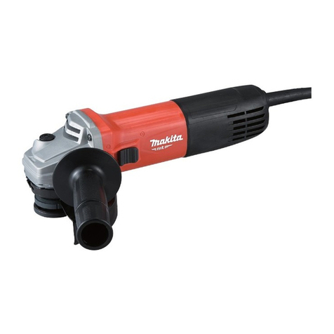
Makita 9560CV User manual

a
9561CV
___
Angle
Grinder
2.800
-
10,5001min
289
mm
(11 318”) 1
7
kg
(3
7
Ibs)
518”
100
mm
(4”)
MODEL 9560CV
115
mm
(4-112”) MODEL 9564CV
100
mm
(4”)
MODEL
9563CV
125
mm
(5”)
MODEL
9565CV
115
mm
(4-112”) MODEL 9561CV
9565CV
I
2,800
~~
10,50O/min.
I
299
mm
(11-314”)
INSTRUCTION MANUAL
1
8
kg
(4.0
Ibs)
518”
DOUBLE
INSULATION
SPECIFICATIONS
MODEL
1
No
load speed
(RPM)
I
Overall
lenqth
I
Net weiaht
1
Spindle thread
9560CV
1
2,800 10,5001min
1
289
mm
(11 318”)
1
1
7 kq (3.7
Ibs)
I
MI0
x
1 25
9563CV
I
2,800
~
10,5001min.
I
299
mm
(11-314”)
1
1.8 ka (4.0
Ibsl
1
MI0
x
1.25

GENERAL SAFETY RULES
USAooz-i
(For
All
Tools)
WARNING!
Read and understand all instructions.
Failure
to follow
all
instructions listed below, may result
in
electric
shock, fire and/or serious personal injury.
SAVE
THESE
INSTRUCTIONS
Work Area
1.
Keep your work area cleanandwell
lit.
Clutteredbenches and dark areas invite
accidents.
2.
Do
notoperate powertools
in
explosiveatmospheres, suchas
in
the presence
of flammable liquids, gases, or dust. Power tools create sparks which may
ignite the dust or fumes.
3.
Keep bystanders, children, and visitors away while operating a power tool.
Distractions can cause
you
to lose control.
Electrical Safety
4.
DoubleInsulatedtools are equippedwitha polarizedplug (oneblade is wider
than the other.) This plug will
fit
in a polarized outlet only one way. If the
plug does not fit fully in the outlet, reverse the plug. If
it
still does not
fit,
contact a qualified electrician to install a polarized outlet.
Do
not change
the plug in any way. Double insulation
H
eliminates the need for the three
wire grounded power cord and grounded power supply system.
5.
Avoid body contact with grounded surfaces such as pipes, radiators, ranges
and refrigerators. There is an increased risk
of
electric shock
if
your body is
grounded.
6.
Donotexpose powertools torainor wet conditions. Water enteringa power
tool
will
increase the risk
of
electric shock.
7.
Do
not abuse the cord. Neverusethe cord to carry the tools or pullthe plug
from an outlet. Keep cordawayfrom heat, oil, sharpedgesor moving parts.
Replace damaged cords immediately. Damaged cords increase the risk
of
electric shock.
8.
Whenoperatingapowertooloutside, usean outdoor extensioncordmarked
"W-A"
or "W." These cords are rated for outdoor use and reduce the risk
of
electric shock.
Personal Safety
9.
Stayalert, watchwhat youare doingandusecommonsense when operating
a power tool.
Do
not use tool while tired or under the influence of drugs,
alcohol, or medication.
A
moment
of
inattention while operating power tools
may result
in
serious personal injury.
10.
Dress properly. Donotwear loose clothingor jewelry. Containlong hair. Keep
your hair, clothing, andgloves away frommovingparts. Looseclothes, jewelry
or long hair can be caught
in
moving parts.
2
11.
Avoid accidental starting. Be sure switchis
off
before plugging
in.
Carrying
tools
with
your finger onthe switchor plugging in tools that have the switch
on invites accidents.
12.
Remove adjusting keys or wrenches before turning the tool on. A wrench
or a key thatis leftattachedtoa rotatingpartof the tool mayresult
in
personal
injury.
13.
Do
notoverreach. Keepproper footing andbalance atalltimes. Properfooting
and
balance
enables better control of the tool in unexpected situations.
14.
Use safety equipment. Always wear eye protection. Dust mask, nonskid
safety shoes, hard hat, or hearing protection must be used for appropriate
conditions.
Tool
Use and Care
15. Use clamps or other practical way to secure and support the workpiece to
a stableplatform. Holdingthe work by handor against your body is unstable
and may lead to
loss
of control.
16.
Do notforce tool. Use the correct toolfor your application. The correct tool
will do the job better and safer at the rate for which
it
is designed.
17. Do not use tool if switch does not turn
it
on or off. Any tool that cannot
be controlled
with
the switch is dangerous and must be repaired.
18.
Disconnectthe plugfrom the power source beforemakingany adjustments,
changing accessories, or storing the tool. Such preventive safety measures
reduce the risk
of
starting the tool accidentally.
19.
Store idle tools out of reach of children and other untrained persons.
Tools
are dangerous
in
the hands of untrained users.
20.
Maintain
tools
with care. Keep cutting tools sharp and clean. Properly
maintained tools,
with
sharp cutting edges are less likely tobindand are easier
to control.
21.
Check for misalignment or binding of moving parts, breakage of parts, and
any other condition that may affect the tools operation. If damaged, have
the tool serviced before using. Many accidents are caused by poorly
maintained tools.
22. Use only accessories that are recommended by the manufacturer for your
model. Accessories that may be suitablefor onetool, maybecomehazardous
when used on another
tool.
SERVICE
23.
Tool
service must be performed only by qualified repair personnel. Service
or maintenance performed by unqualified personnel could result
in
a risk of
injury.
24.,When servicing a tool, use only identical replacement parts. Follow
instructionsinthe Maintenance sectionof this manual. Use of unauthorized
partsor failure tofollow MaintenanceInstructionsmay create a risk of electric
shock
or
injury.
3

Specific Safety Rules
USBOOS-l
1.
Always useproper guardwithgrinding wheel.
A
guard protectsoperator from
broken wheel fragments.
2.
Accessoriesmust be ratedfor at least the speed recommendedon the tool
warning label. Wheels and other accessories running over rated speed can
fly apart and cause injury.
3.
Holdtool by insulatedgrippingsurfaceswhen performinganoperationwhere
the cutting tool may contact hidden wiring or its own cord. Contact with
a
"live" wire will make exposed metal parts of the tool "live" and shock the
operator.
4.
Keep guards in place.
5. Useonly wheels havingamaximumoperating speedat least as highas
"No
Load
RPM"
markedon the tool's nameplate.When using depressedcenter
wheels, be sure to use only fiberglass-reinforced wheels.
6.
Check the wheel carefully for cracks or damage before operation. Replace
cracked or damaged wheel immediately.
7.
Use only flanges specified for this tool.
8.
Be careful not to damage the spindle, the flange (especially the installing
surface) or the lock nut. Damage to these parts could result
in
wheel
breakage.
9.
Hold the tool firmly.
IO.
Keep hands away from rotating parts.
11.
Make sure the wheel is not contacting the workpiece before the switch is
turned on.
12.
Beforeusing the tool on an actual workpiece, let
it
run for a while. Watch
for vibration or wobbling that could indicate poor installation or a poorly
balanced wheel.
13.
Use the specified surface of the wheel to perform
the
grinding.
14. Watch out for flying sparks. Holdthe tool
so
that sparksfly away from you
15.
Do
not leave the tool running. Operate the tool only when hand-held.
16.
Do
nottouch the workpieceimmediatelyafter operation;
it
may be extremely
and other persons or flammable materials.
hot and could burn your skin.
SAVE
THESE INSTRUCTIONS.
4

SYMBOLS
The followings showthe symbols used for
tool.
v
....................................
volts
A
....................................
amperes
Hz
....................................
herts
?.,
....................................
alternating current
b
....................................
no load speed
H
....................................
Class
II
Construction
.../
min
...................................
revolutionsor reciprocation per minute
5

FUNCTIONALDESCRIPTION
Switch
action
CAUTION:
Before plugging in the tool, always check to see that the switch actuates properly and
returnsto the
"OFF"
positionwhen the side
of
the switch lever isdepressed.
To start the tool, slide the switch lever to
"I"
position.
For continuousoperation, depress the front
of the switch lever and then slide to
"I"
position as above. The switch is locked on
the positionfor continuousoperation.
To stop the tool from the locked position,
slide the switch lever to
"0"
position with
depressingits rear part.
Depressingthe rear
of
the switch lever.
Switch
lever
Speed adjustingdial
The rotatingspeed can be changed by turning the speed adjustingdial to a given number
setting from
1
to
5.
Higher speed is obtainedwhen the dial isturned inthe directionof number
5.
And lower speed is obtained when
it
is turned in the directionof number
1.
Referto the table below for the relationshipbetweenthe numbersettings on the dial and
the approximate rotatingspeed.
I
Number
I
RPM
(mid
2800
1
4000
1
6500
1
9000
1
10500
k3peedadjusting dial
CAUTION:
The speedadjustingdialcan be turned only as far as
5
and back
to
1.
Do
notforce
it
past
5
or
1,
or the speed adjustingfunction may no longer work.
6

ASSEMBLY
Installingand removing wheel cover
Installing
Pullthe lever inthe direction
of
the arrow after loosening the screw.
Installthe wheel cover on the bearing box by adjusting the convex
of
the wheel cover to
Turnthe wheelcover
by
180
degrees. Fasten
it
withthe screw after pullingthe lever the
For the working purpose, the settingangle of the wheel cover can be adjusted with the
Removing wheel cover
Followthe installation procedure
in
reversetoremovethewheelcover
the concaveof the bearing box.
directionof the arrow.
lever
Shaft
lock
Pressthe shaft lock to prevent spindle rota-
tion when installing or removing acces-
sories.
CAUTION:
Never actuate the shaft lock when the
spindle is moving. The tool may be dam-
aged.
Installingside grip (auxiliaryhandle)
Screw the side grip on the tool securely.
The side grip canbe installed on either side
of
thetool, whichever
is
convenient.
Shaft
lock
7

Installing
or
removingthe depressed center wheel
CAUTION:
Always be sure that the tool is switched off and unpluggedbefore installingor removing
the wheel.
Once the edge of the wheel has been
rounded
off
by use, the wheel
may
be
workedinbothA and
B
direction.
Mountthe inner flange onto the spindle.
Fit
the wheel on over the inner flange and
screw the lock nut onto the spindle.
~-~___-
-
Lock
nut
-a
e
Depressed
Inner flange
To tighten the lock nut, pressthe shaft lock
firmly
so
that the spindle cannot revolve,
then use the lock nut wrench and securely
tighten clockwise.
WARNING:
Only actuatethe shaft lock when the spin-
dle is not moving.
~
OPERATION
CAUTION:
After operation,always switch
off
the tool and wait until the wheel has come to a com-
plete stop beforeputtingthe tool down.
Hold the tool firmly. Turn the tool on and
then apply the wheel or disc to the work-
piece.
In general, keep the edge of the wheel or
disc at an angle
of
about
15"
-
30"
to the
workpiece surface.
During the break-in period with a new
wheel, do not work the grinder in the
B
direction or
it
will
cut into the workpiece.
8

WARN1
NG
:
It
shouldnever be necessary to force the tool. The weight of the
tool
applied adequate
pressure.Forcingand excessive pressurecouldcause dangerouswhen wheel breakage.
Continueduse
of
a
worn-out wheel may result in wheel explosionand serious personal
injury. Depressedcenter wheel should not be used after it has been worn down to
75 mm (3")
in
diameter for Models 9560CV, 9563CV or 90 mm (3-1/2") for
Models
9561CV, 9564CV and 9565CV indiameter.Useof the wheel after this point is unsafeand
it shouldbe removedfrom service and rendered unusableby intentionaldestruction.
The tools equippedwith electronicfunction are easy to operatebecause
of
the following
features.
Electronic speedcontrol for obtainingconstantspeed
Possible to get fine finish, because the rotatingspeed is kept constantlyeven under the
loadedcondition.
Soft start feature
Safety and soft start becauseof suppressed startingshock.
Overloadprotector
When the tool would be employedover the admissible load,
it
will stop automatically to
protect the motor andwheel. Whenthe load will come to the admissiblelevelagain,
the
tool can be startedautomaticallv.
MAINTENANCE
CAUTION:
Always be sure that the tool is switched off and unpluggedbefore attempting to perform
inspectionor maintenance.
Repair and maintenance
The tool and its opening vents for cooling
air have
to
be always kept clean.When the
foreign matters clog such parts. they have
to be taken off.
Inhalation
vent
I
To maintainproduct SAFETY and RELIABILITY, repairs,any other maintenance or adjust-
mentshouldbe performedby MakitaAuthorizedor Factory Service Centers, always using
Makitareplacementparts.
9

ACCESSORIES
CAUTION:
These accessories or attachments are recommendedfor use with your Makitatool specified in this
manual. The use of any other accessories or attachments might present
a
risk of injury to persons.
The accessoriesor attachmentsshouldbe usedonly inthe proper and intendedmanner.
Size
4"xlWx518"
4-1/2"
x
5B"
x
7W
5"X511)"X78"
@
Wheelcover
PanNo.
I
For Model
Grit
For
Model
40
7
9560CV
80
9563cv
-
100
40
M)
9561CV
80
9564cv
-
100
40
60
-
-
-
7
95650'
-
100
@
Depressed
center
wheels
Pan
No.
I
Size
I
Grit
741402-8
I
4,,x3~16,,x5B,,
I
18ulk)
7414026-1
741402C
7414258
4x3/16"~518"
36
7414052-1
7414W2P
I
24
-=
41R"
x
1/4
x
7W
74142481
9563cv
mcv
51
9565CV
Q
Inner
flange
Size
I
Part~o.
I
For Model
9561CV
45
I
224368-2
I
9564CV
9565CV
@
Multi-disc
Pat
NO.
7420380A
74203808
7420380C
7420380D
794332-2A
794332-28
794332-2c
794332-20
7943314.4
79433148
7943314C
794331dD
@
Locknut
Size
I
Part No.
I
ForModel
9561cv
5/8-45
I
224566-8
1
9564CV
9565cv
10

@
Rubberpad
743036-3
743015-1
9565CV
@
Abrasivediscs
(For
abrasive
disc)
Part
No.
Part
No
I
Diameter
Per
pkg
74203603
For
Model
4'
794107-8
794108-8
142072-A-5
742073-A-5
742074-A-5
742075-A-5
742076A-5
742072-8
742073-8
742074-8
742075-0
7420768
742087-0
7420400
794105-A-5
80
120
-
24
30
50
5
80
5"
120
24
36
50
1
80
120
-
-
-
-
-
-
-
-
794105-A-5
I
794106A-5
5
794107-A-5
-1
4-1/2''
794104-8
For
Model
9560CV
9563CV
3561CV
3564CV
E65CV
9565CV
9565CV
@
Wire cup brush
75
@
Wire bevel brush85
8
Wheel guard assembly
(For
cut-off
wheel)
For
Model
9560CV. 9563CV
Part
No.
192476-6
11

@
Cut-offwheel
Pan
No.
Size Grit Wheels per
pkg.
For use
724104-110 4"
x
3/32"
x
5"' 36
10
For
masonry
andconcrete.
724107-510 4"
x
5/64"
x
5B" 46 10 For steel andcast iron.
For
Model
9560cv
9563CV
Knot-Type Knotted-Twist
Wire cup brush
9564CV
Wire cup brush
StringerBeadTwist
Wire brushwheel
FullCable Twist
Wire brushwheel
Lock nutwrench
0
9565CV
743213-E
Grip
Part
No.
152490-4
Part
No.
I
For Model
Pan
No.
I
For Model
9561CV
743212-A
I
9564CV
9565CV
Part
No.
I
ForModel
9561CV
9565CV
I
IV
12

+
57
56
55
54
50
48
G
47
@-
46
13

ITEM NO. DESCRIPTION
1
2
3
4
5
6
7
8
9
10
11
12
13
14
15
I6
17
18
19
20
21
22
23
24
25
26
27
28
29
30
31
PIN CAP
COMPRESSIONSPRING
8
GEAR HOUSINGCOMPLETE
HEX. NUT M6
FLAT WASHER
6
SPIRAL BEVEL GEAR
11
LOCK SPRING 12
RETAININGRING S-12
BALL BEARING6001LLB
FLAT WASHER 12
GEAR HOUSINGCOVER
FAN
57
ARMATURE ASSY
INC. 12.14-16
INSULATION WASHER
FLAT WASHER
7
BALL BEARING 627DDW
LABYRINTH RUBBER RING 22
MAGNET SLEEVE
STOP RING E-4
BAFFLE PLATE
TAPPING SCREW 4x60
RETAINER
INSULATION COVER
FIELD
TAPPING SCREW 4x18
STRAIN RELIEF
SWITCHBLOCK
SWITCH STll5A-40
COVER
SWITCHLEVER
COMPRESSION SPRING 4
NO USED ITEM NO DESCRIPTION
1
32
1
33
1
34
1
35
1
36
1
37
1
38
1 39
I
40
1
41
1
42
1
43
1 44
45
1
46
1
41
1
48
1
49
1
50
1
51
1
52
2
53
2 54
2 55
1
56
2 57
1
58
1
59
1
BO
1
1
1
BRUSH HOLDER
MOTOR HOUSING
MAKITA LABEL
SWITCHKNOB
CORD GUARD 8
POWER SUPPLY CORD
REAR COVER
TAPPING SCREW 4x18
INDICATION LABEL
CONTROLLER
A
C
CARBON BRUSH CB-318
BRUSH HOLDER
TAPPING SCREW PT3XlO
NAME PLATE
LOCK NUT
10-35
INNER FLANGE 35
WHEEL COVER
PAN HEAD SCREW M5XI
6
SPINDLE
LABYRINTH RING
NO USED
1
1
1
1
1
1
1
1
1
1
1
1
4
1
1
1
1
1
1
1
HEX. SOCKET HEAD BOLT M4X16 4
WHEEL COVER BASE
1
BEARINGBOX COMPLETE
1
0
RING 52
1
SPIRAL BEVEL GEAR 38
1
PIN
1
0
RING
6
1
TAPPING SCREW 4x28 4
WAVE WASHER
6
1
14

Some dust created by power sanding, sawing, grinding, drilling, and other
construction activities contains chemicals known
[to
the State of Califomia]
to
cause cancer, birth defects or other reproductive harm. Some examples of
these chemicalsare:
0
Leadfrom lead-based paints,
0
Crystalline silicafrom bricksand cement and other masonry products, and
0
Arsenic andchromium from chemically-treated lumber.
Your risk from these exposures varies, depending on how often you do this
type of work.
To
reduce your exposure
to
these chemicals: work in a well
ventilated area, and work with approved safety equipment, such as those
dust masksthat are specially designed
to
filter out microscopicparticles.
MAKITA
LIMED
ONE YEAR WARRANTY
Warranty
Policy
Every Makita tool is thoroughly inspected and tested before leaving the factory. It is warranted to
be free of defects from workmanshlp and materials for the period of ONE YEAR from the date
of
original purchase. Should any trouble develop during this one-year period. return the COMPLETE
tool, freight prepaid, to one of Makita’s Factory or Authorized Service Centers. If inspection shows
the trouble is caused by defective workmanship or material, Makita
will
repair (or at our option,
replace) without charge.
This Warranty doesnot apply where:
repairs have been made or attempted by others:
repairs are required because of normal wear and tear:
The tool has been abused, misused or improperly maintained;
alterationshave been made to the tool.
1
IN
NO EVENT SHALL MAKITA BE LIABLE FOR ANY INDIRECT, INCIDENTAL
OR
CON-
SEQUENTIAL DAMAGES FROM THE SALE
OR
USE OFTHE PRODUCT. THIS DISCLAIMER
APPLIES BOTH DURING AND AFTER THETERM OFTHIS WARRANTY.
MAKITA DISCLAIMS LIABILITY FOR ANY IMPLIED WARRANTIES, INCLUDING IMPLIED
WARRANTIES OF “MERCHANTABILITY” AND “FITNESS FOR A SPECIFIC PURPOSE,”
AFTER THEONE-YEAR TERM OFTHISWARRANTY.
This Warranty gives you specific legal rights, and you may also have other rights which vary from
state
to
state. Some states do not allow the exclusion or limitation of incidental or consequential
damages,
so
the above limitation or exclusion may not apply to you. Some states do not allow
limitation onhow long an implied warranty lasts,
so
the above limitation may not apply to you.
Makita
Corporation
3-11
-8, Sumiyoshi-cho,
Anjo,
Aichi 446-8502
Japan
884311A061 PRINTED INJAPAN
Other manuals for 9560CV
3
This manual suits for next models
4
Table of contents
Other Makita Grinder manuals

Makita
Makita GA7001 Quick start guide

Makita
Makita GA5020 User manual

Makita
Makita DGA404 User manual

Makita
Makita 9564CR Manual

Makita
Makita 9005BY User manual

Makita
Makita 906 User manual

Makita
Makita GA5040R User manual

Makita
Makita 9520NB User manual

Makita
Makita GA021G User manual

Makita
Makita 9561CR Manual

Makita
Makita N9501B User manual

Makita
Makita GA7020Y User manual

Makita
Makita M908 User manual

Makita
Makita 906H User manual

Makita
Makita GA4040C User manual

Makita
Makita 9556NB User manual

Makita
Makita DGA520 User manual

Makita
Makita 9558HNR User manual

Makita
Makita 9561CR User manual

Makita
Makita GA7061 User manual