Makita 9564HR Manual

Model No.
Description
PRODUCT
CONCEPT AND MAIN APPLICATIONS
P 1/ 14
Specification
Standard equipment
Note: The standard equipment may vary by country or model variation.
9564HR / 9565HR
Angle Grinder 115mm (4-1/2") /
Angle Grinder 125mm (5")
Models 9564HR and 9565HR have been developed as successor
models of 9564H and 9565H with soft start and anti-restart function.
Their main features are:
・Soft start: minimizes start-up shock, and makes the tool start smoothly.
・Anti-restart function: prevents accidental start-up even if the tool is
plugged to power source.
・SJS (Super Joint System): Lock spring positioned at the junction
between spiral bevel gear and armature shaft serves as a shock absorber.
・O ring for leakproof of grease
・Tool-less wheel cover: adjustable to any desired position
・Easy-to-grip shape
・Cord guard with higher flexibility
Dimensions: mm (")
Width (W)
Height (H)
Length (L)
Model 9564HR
299 (11-3/4)
130 (5-1/8)
111 (4-3/8)
9565HR
140 (5-1/2)
L
H
Continuous Rating (W)
Voltage (V) Cycle (Hz) Input Output Max Output (W)
110 10.5 1,100 700 1,30050/60
5.3 1,100 700 1,30050/60
5.0 1,100 700 1,30050/60
4.8 1,100 700 1,30050/60
220
230
240
Current (A)
Optional accessories
Depressed center wheel
Rubber pad
Dust collecting wheel cover
Abrasive disc
Wire cup brush
W
Model
No load speed:
Diameter
Hole diameter
Wheel size:
mm (")
Protection against electric shock
Power supply cord: m (ft)
*With Side grip
Weight according to
EPTA-Procedure 01/2003*: kg (lbs)
9564HR 9565HR
115 (4-1/2)
2.5 (8.2)
2.3 (5.1)
12,000
125 (5)
Grounding
22.23 (7/8)
Max thickness 6.4 (1/4)
Super Joint System (SJS) Yes
No
Yes
No
Constant speed control
Soft start
Electronic current limiter
YesAnti-restart function
Variable speed control by dial No
Electronic
control
TECHNICAL INFORMATION
minˉ¹= rpm
Depressed center wheel
Lock nut wrench
Side grip
Wheel cover for wire cup brush
Wire bevel brush
Wheel cover for wire bevel brush
Abrasive cut off wheel
Wheel cover set
Inner flange
Lock nut
Super flange
Sanding lock nut
Head cover
Dust collecting wheel guard
Elbow joint Ass’y
Joint
Dust cover attachment set
Specificatiion
OFFICIAL USE
for ASC & Sales Shop

P 2/ 14
Repair
[1] NECESSARY REPAIRING TOOLS
CAUTION: Repair the machine in accordance with “Instruction manual” or “Safety instructions”.
Code No. Description Use for
1R014 1/4" Hex. shank bit M4 removing / tightening M4x16 Hex socket head bolt
1R027 Bearing setting pipe 18-10.2 removing Ball bearings 6001LLB and 6201DDW
1R028
1R030
1R031
1R032
1R033
1R035
1R045
1R258 V block
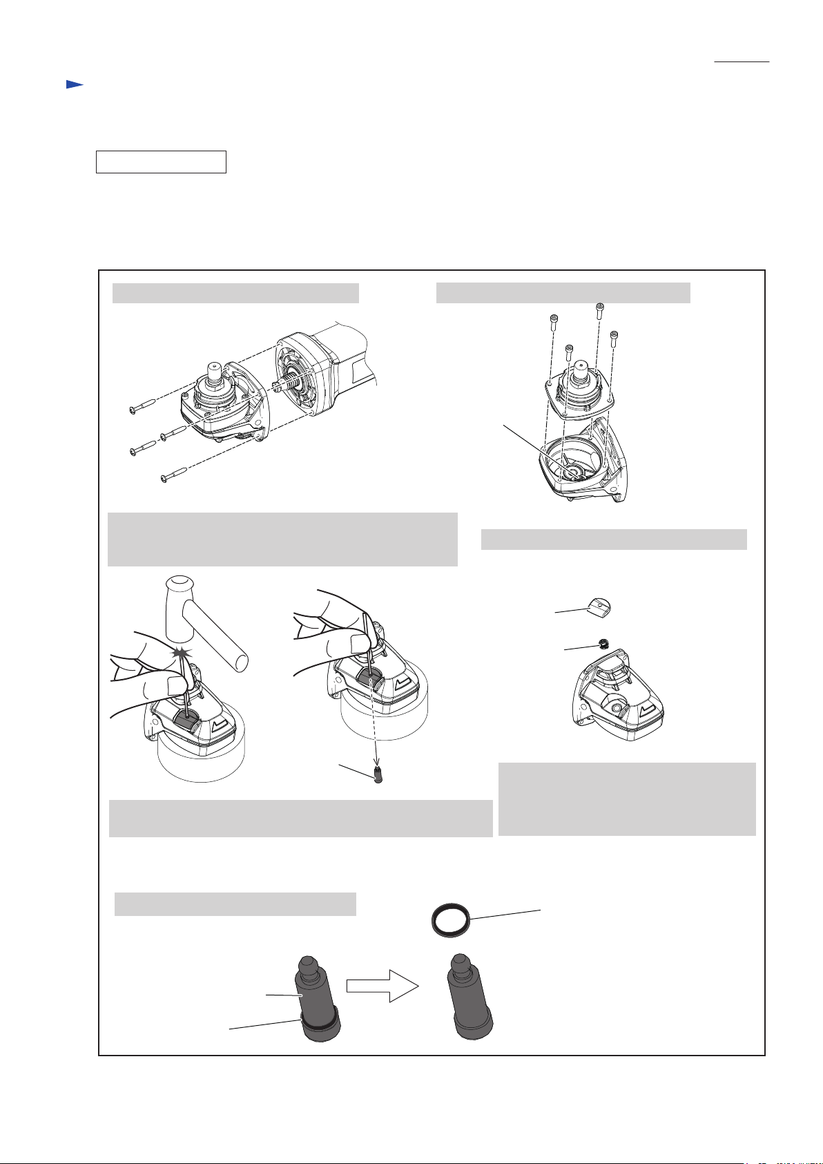
1R268 Spring pin extractor M3
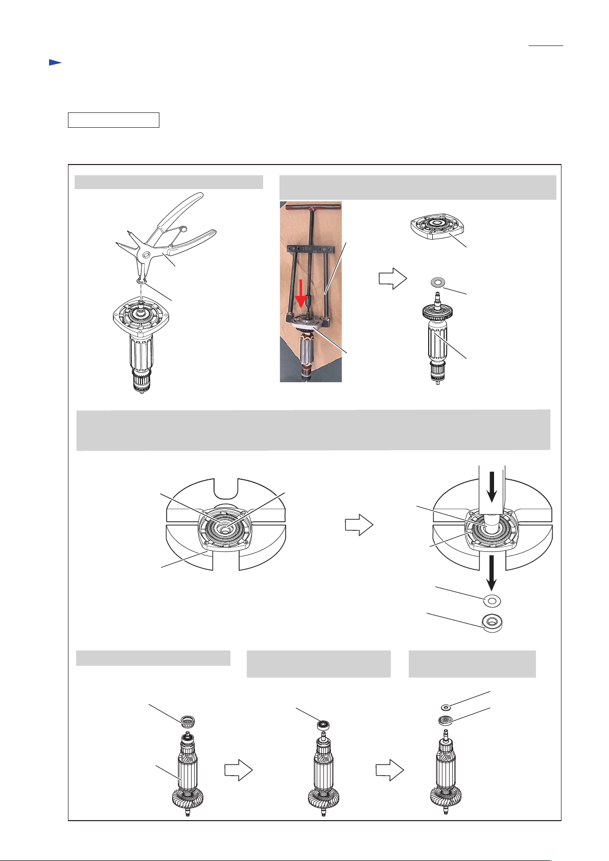
1R269 Bearing extractor
1R281 Round bar for arbor 7-50
Round bar for arbor 9-501R283
1R291 Retaining ring S and R pliers
1R340 Bearing retainer wrench
1R350 Ring 60
Bearing setting pipe 20-12.2
Bearing setting pipe 25-17.2
Bearing setting pipe 28-20.2
Bearing setting plate 8.2
Bearing setting plate 10.2
Bearing setting plate 15.2
Gear extractor
supporting Bearing box when removing Spiral bevel gear 38
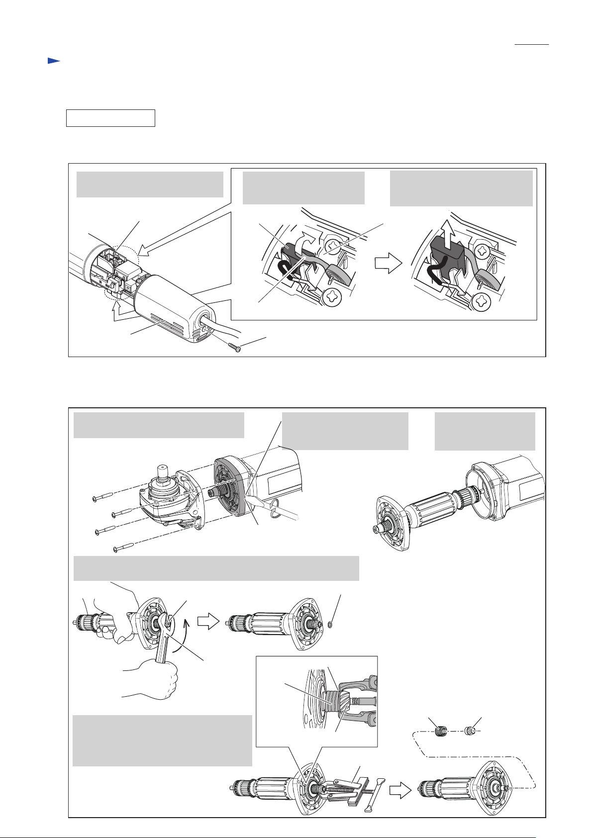
removing Shoulder pin 7 from Pin cap
removing Spiral bevel gear 11 from Armature
removing Spindle from Spiral bevel gear 38
Locking Switch knob when removing Switch lever
removing / assembling Retaining ring S-12 from / to Armature
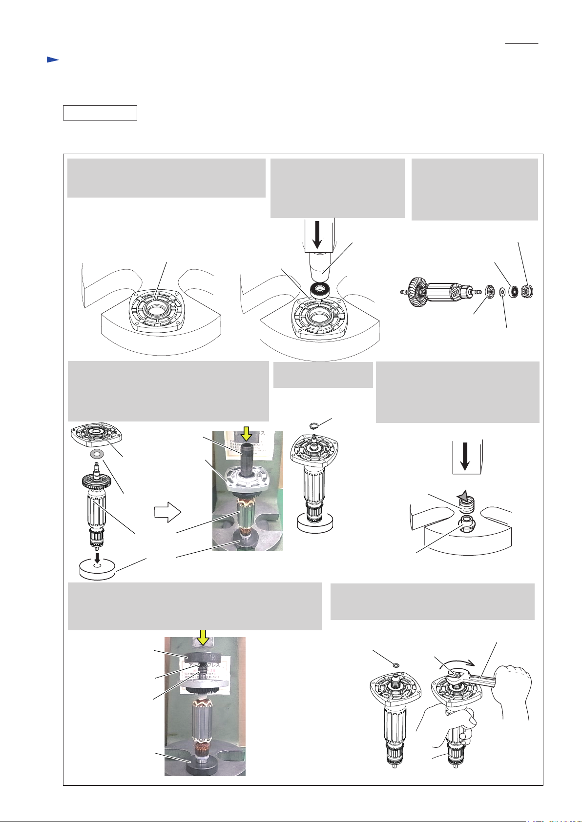
removing / assembling Bearing retainer 19-33
supporting Gear housing when removing Shoulder pin 7
assembling Spiral bevel gear 38 to Spindle
assembling Ball bearing 6001LLB to Gear housing cover
supporting Armature when assembling Ball bearing 6001LLB
assembling Spiral bevel gear 11 to Armature
supporting Bearing box when assembling Spiral bevel gear 38
removing Armature from Gear housing cover
assembling Gear housing cover with Ball bearing 6001LLB to Armature
[2] LUBRICATION
Apply Makita grease R. No.00 to the portions designated with the black triangle, and Disulfide molybdenum
to the portions designated with the gray triangle, protect parts and product from unusual abrasion.
Fig. 1
Item No. Description AmountPortion to lubricate Lubricant
3
6
7
6
7 Lock spring 12
Armature
3 Gear housing complete Gear room
Cylindrical portion where armature shaft is inserted
Cylindrical portion which accepts 6 ‘s drum portion
Spiral bevel gear 11
15g
a little
a little
Makita grease R No.00
Disulfide molybdenum

P 3/ 14
Repair
[3] DISASSEMBLY/ASSEMBLY
[3]-1. Armature, Ball bearings 6001LLB/627DDW, Spiral bevel gear 11
DISASSEMBLING
(1) Disconnect Carbon brushes from Commutator as drawn in Fig. 2.
(2) Remove Armature ass’y with Gear housing cover from Motor housing and then disassemble Spiral bevel gear section
as drawn in Fig. 3.
Notch between Gear housing cover
and Motor housing
Remove Rear cover by unscrewing
4x18 Tapping screw.
Shift Spiral spring from
Carbon brush top and hook it
on the edge of Brush holder.
Pull up Carbon brush from Brush
holder in a half way to detach from
Commutator. No need to remove.
Rear cover 4x18 Tapping screw
1. Disassemble Gear housing section by
unscrewing four 4x28 Tapping screws.
2. Remove Gear housing cover
from Motor housing with
a slotted screwdriver.
3. Armature is removed
together with
Gear housing cover.
4. Remove M6 Hex nut with a wrench 10 by turning counterclockwise.
And then, remove Flat washer 6.
Brush holder
Fig. 2
Fig. 3
Wrench 10
M6 Hex nut Flat washer 6
5. Remove Spiral bevel gear 11 with 1R269.
Note: When Lock spring 12 is left on
Armature shaft, remove it with
1R269 in the same way. 1R269
4x28 Tapping
screw (4 pcs.)
Edge of Brush holderCarbon brush
Tail of spiral spring
Spiral bevel gear 11
Lock
spring 12
Jaws of 1R269
Lock spring 12 Spiral bevel gear 11

P 4/ 14
Repair
[3] DISASSEMBLY/ASSEMBLY
[3]-1. Armature, Ball bearings 6001LLB/627DDW, Spiral bevel gear 11 (cont.)
DISASSEMBLING
(3) Remove Gear housing cover from Armature as drawn in Fig. 4.
Fig. 4
1. Remove Retaining ring S-12 with 1R291. 2. Remove Armature and Flat washer 12 from Gear housing cover
with 1R045.
3. Put Gear housing cover on the U shaped portion of Arbor press table so that the small hole side of Gear housing
cover faces upwards.
Then, press down Ball bearing 6001LLB with 1R027.
Flat washer 12
Gear housing cover
with Ball bearing
6001LLB
1R045
Gear housing
cover
Gear housing
cover
4.Remove Labyrinth rubber ring 22. 5.Remove Ball bearing 627DDW
with 1R269.
6.Remove Insulation washer
and Flat washer 7.
Ball bearing
6001LLB
Ball bearing
6001LLB
Insulation
washer
Flat washer 7
1R027
Small hole side of
Gear housing cover
U shaped portion of
Arbor press table
Ball bearing
627DDW
Labyrinth
rubber ring 22
Armature ass’y
Retaining ring S12
1R291
Armature
Flat washer 12

P 5/ 14
Repair
[3] DISASSEMBLY/ASSEMBLY
[3]-1. Armature, Ball bearings 6001LLB/627DDW, Spiral bevel gear 11 (cont.)
ASSEMBLING
(1) Assemble Armature to Gear housing cover as drawn in Fig. 5.
Fig. 5
1. Put Gear housing cover on U shaped portion of
Arbor press table so that the large hole side of
Gear housing cover faces upwards.
2. Pressfit Ball bearing 6001LLB
into the bearing room of
Gear housing cover with
1R031.
3. Assemble Insulation washer,
Flat washer 7, Ball bearing
627DDW and Labyrinth
rubber ring 22 to Armature
on the commutator end.
4. Stand Armature on 1R032, and pass Flat washer
12 through Armature shaft, then press down
Ball bearing 6001LLB in Gear housing cover
with 1R028 so that Armature shaft protrudes
from Ball bearing 6001LLB .
7. Stand Armature on 1R032, then pressfit Spiral bevel gear 11
with Lock spring 12 to Armature shaft using 1R033 carefully
until the thickness for Flat washer 6 and M6 Hex nut can be
secured to Armature shaft.
Ball bearing
6001LLB
1R031
Large hole side of Gear housing cover
6. Apply Disulfide molybdenum
to the inside of Lock spring 12.
Refer to Fig. 1 of page 2.
Assemble Lock spring 12 to
Spiral bevel gear 11 with Arbor press.
5. Assemble Retaining
ring S-12 with 1R291.
8. Pass Flat washer 6 through Armature shaft, and
then tighten M6 Hex nut by turning clockwise
with Wrench 10.
Lock spring 12 Disulfide molybdenum
1R032
1R032
1R028
1R033
Lock spring 12
Spiral bevel gear 11
Insulation washer
Flat washer 7
Ball bearing 627DDW
Labyrinth rubber ring 22
Wrench 10
M6 Hex nut
Flat washer 6
Retaining
ring S-12
Gear housing cover
with Ball bearing
6001LLB
Armature
Flat washer 12

P 6/ 14
Repair
[3] DISASSEMBLY/ASSEMBLY
[3]-1. Armature, Ball bearings 6001LLB/627DDW, Spiral bevel gear 11 (cont.)
ASSEMBLING
(2) Assemble Gear housing cover and Armature to Motor housing, and assemble Gear housing section
to Motor housing as drawn in Fig. 6.
Fig. 6
Before assembly, make sure that Switch knob comes to the left side as drawn below, and the angle between Spindle
and Switch knob is 90°.
Switch knob
on left side of Motor housing
Spindle
Switch knob
right hand thumb
Spindle

P 7/ 14
Repair
[3] DISASSEMBLY/ASSEMBLY
[3]-2. Spiral bevel gear 38, Ball bearing 6201DDW
DISASSEMBLING
2. Press down Spindle with 1R281.
Labyrinth ring is removed together with Spindle.
Spiral bevel gear 38 is removed.
1. Put Bearing box onto 1R258 so as not to touch Labyrinth ring.
And give impacts to Spindle with Arbor press carefully.
Labyrinth ring
Spindle
Spindle
Spindle
Labyrinth ring
Ram
Labyrinth ring
1R258 1R258
1R340
1R027
Ball bearing 6201DDW
Note: Do not use the removed Ball bearing 6201DDW.
It is because Ball bearing 6201DDW is damaged
when removed from Bearing box.
Bearing retainer 19-33
1R281
Spiral bevel gear 38
3. Remove Bearing retainer 19-33 by turning 1R340
counterclockwise.
4. Put Bearing box on U shaped Arbor press table so that
the bearing retainer installation side faces downwards.
And then, press down Ball bearing 6201DDW with 1R027.
Ball bearing 6201DDW
Ball bearing
6201DDW
(2) Disassemble the separated Bearing box section as drawn in Fig. 8.
Fig. 8
Fig. 7
1. M4x16 Hex socket head bolt is adhesive, and therefore
remove them by loosening with Hex wrench 3 first, then
use an cordless impact driver with 1R014.
Then, remove Bearing box section.
2. If it is difficult to remove Bearing box section,
tap the portion drawn below with a plastic hammer.
Bearing box section is removed from Gear housing.
Bearing box
Note: Bearing box section can be separated from Gear housing without disassembling Motor section.
(1) Disassemble Bearing box section as drawn in Fig. 7.
M4x16 Hex socket
head bolt (4 pcs.)

P 8/ 14
Repair
[3] DISASSEMBLY/ASSEMBLY
[3]-2. Spiral bevel gear 38, Ball bearing 6201DDW (cont.)
ASSEMBLING
(1) Make sure that O ring 52 is mounted to Bearing box as drawn in Fig. 9.
Fig. 9
O ring 52
Bearing box
1. Set Spindle to 1R035.
2. Assemble Labyrinth
ring to Spindle as
drawn below.
Note: Labyrinth ring
is directional.
3.Pressfit Bearing box to
Spindle with 1R030.
4. Assemble Spiral bevel gear 38
in the same way as Bearing box
section.
Labyrinth ring 1R030
Bearing box
Spindle
(2) Assemble Ball bearing 6201DDW and Bearing retainer 19-33 to Bearing box. Refer to Fig. 8 of the previous page.
Note: Be sure to use new Ball bearing 6201DDW.
(3) Assemble Bearing box section by mounting Spindle and Spiral bevel gear 38. And then, assemble them to Gear housing.
See Fig. 10.
Spiral bevel gear 38
Fig. 10
M4x16 Hex socket
head bolt (4 pcs.)
5. Tighten M4x16 Hex socket head bolts to secure Bearing box section to Gear housing.
Note: Apply Loctite 243 or ThreeBold 1342 to threads of M4x16 Hex socket head bolts.

P 9/ 14
Repair
[3] DISASSEMBLY/ASSEMBLY
[3]-3. Switch lever
DISASSEMBLING
ASSEMBLING
Assemble Switch knob to Switch lever as drawn in Fig. 12.
(1) Separate Rear coveras per the left drawing in Fig. 2.
(2) Disassemble Switch lever as drawn in Fig. 11.
Fig. 11
Fig. 12
3. While bending Switch lever carefully,
pull it out from Motor housing.
1. Insert 1R283 into the space between
Switch knob and the rib of Motor housing
to prevent Switch knob from moving,
and push Switch lever strongly toward
Switch-on position.
2. The linkage of Switch knob
is disconnected from
Switch lever, and therefore,
Switch knob is removed.
Switch Lever
Tumbler
Switch Lever
1R283
Rib of Motor housing
Switch knob
Switch Switch
Switch Knob
Tumbler of
Switch Tumbler of
Switch Switch Lever
Switch
knob
2. Engage Switch Knob’s hook
with the framed portion of
Switch lever while seeing
through the Switch knob
assemble hole.
3. Release Switch lever.
So, Switch knob is assembled
to Switch lever.
Switch Lever
Switch
knob
1. Insert Switch lever into Motor housing
until the frame of Switch lever can be
seen through Switch knob assemble hole.
And keep this position to assemble
Switch knob.

P 10/ 14
Repair
[3] DISASSEMBLY/ASSEMBLY
[3]-4. Shaft lock
DISASSEMBLING
(1) Disconnect carbon brushes from the Commutator and then separate Rear cover from Motor housing. as drawn in
Fig. 2 of page 3.
(2) Remove Gear housing and Bearing box from Motor housing and disassemble Shaft lock as drawn in Fig. 13.
Fig. 13
Shoulder pin 7
as shaft lock
Shoulder pin 7
1. Remove Gear housing and Bearing box. 2. Remove Bearing box from Gear housing.
3. Apply 1R268 to Shoulder pin 7 through the small Hole
on Pin cap and tap 1R268 with Hammer.
Shoulder pin 7 comes out from Gear housing complete.
4. Remove Pin cap and Compression spring 8.
Pin cap
Note: Remove 1R268 slowly while holding Pin cap with your finger.
Otherwise Pin cap would be slung by Compression spring 8.
Compression
spring 8
5. Remove O ring 6 from Shoulder pin 7.
Note: Do not use the removed Pin cap.
It is because removal of Shoulder pin 4
damages the inside surface of Pin cap,
producing plastic dust.
O ring 6
O ring 6
Shoulder pin 7

P 11/ 14
Repair
[3] DISASSEMBLY/ASSEMBLY
[3]-4. Shaft lock (cont.)
ASSEMBLING
Fig. 16
(1) Be sure to use a new Pin cap for replacement and to remove all the plastic dust on Shoulder pin 7. (Fig. 15)
Fig.15
Plastic dust
O Ring 6
Shoulder Pin 7
(2) Assemble the Parts for Shaft lock mechanism as drawn in Fig. 16.
Shoulder pin 7
Shoulder Pin 7
2. Assemble Pin cap by pressing it to Shoulder pin 7.
Note: Do not forget to set Compression spring 8 in place.
1. Insert Shoulder pin 7
through the Hole of Gear
housing complete.
Pin cap
Compression spring 8

P 12/ 14
Fig. D-1
Circuit diagram
White
Color index of lead wires' sheath
Circuit in Switch
13
Black
Red
Field
Switch
Polyolefin tube
Brush holder
Straight receptacle #110. t=0.8
L shape receptacle #110. t=0.8
AWG22
AWG18
Magnet wire
Magnet wire
AWG18
M3.5 Insulated terminal
Brush
holder
Power
supply cord
Switch
lever side
Controller
Switch block
Noise
suppressor
Blue lead wire is used for some countries
instead of white.
Blue lead wire is used for some
countries instead of white.
Brown lead wire is used for some countries
instead of white.

P 13/ 14
Fig. D-2
Fix controller’s lead wires
in these lead wire holders.
Place the slacks of Lead wires
to this place.
Do not loosen Lead wires in
Motor housing.
Wiring diagram

P 14/ 14
Cord clamp
Motor housing
Rib
Wiring diagram
Put this Lead wire of Power
supply cord between Rib and
Cord clamp.
Place the slack of Field lead wire
to this place.
Fix Lead wire of Controller
in these Lead wire holders.
Place the slacks of Controller’s
lead wires to this place.
Do not loosen Lead wires in
Motor housing.
Place the slacks of Controller’s
lead wires to this place.
Fig. D-3
Other manuals for 9564HR
1
This manual suits for next models
1
Table of contents
Other Makita Grinder manuals

Makita
Makita 9500D User manual

Makita
Makita 9560CV User manual

Makita
Makita GA030G User manual

Makita
Makita GA9070 User manual

Makita
Makita GA4030 User manual

Makita
Makita GA003G User manual

Makita
Makita M9002 User manual

Makita
Makita GA7020 User manual

Makita
Makita GA5020 User manual

Makita
Makita GA7020 User manual

Makita
Makita DGA521 User manual

Makita
Makita 9015DB Manual

Makita
Makita GA7080 User manual

Makita
Makita DGA506 User manual

Makita
Makita GAG14 User manual

Makita
Makita 9564CR Manual

Makita
Makita GA7011C User manual

Makita
Makita GA4034 User manual

Makita
Makita GD0602 User manual

Makita
Makita 9564PC User manual