Continuous Rating (W)
Voltage (V) Cycle (Hz) Input Output Max. Output(W)
110
120
220
230
240
Models No.
Description
PRODUCT
Current (A)
TECHNICAL INFORMATION
CONCEPTION AND MAIN APPLICATIONS
Specification
Standard equipment
Optional accessories
< Note > The standard equipment for the tool shown may differ from country to country.
P 1 / 10
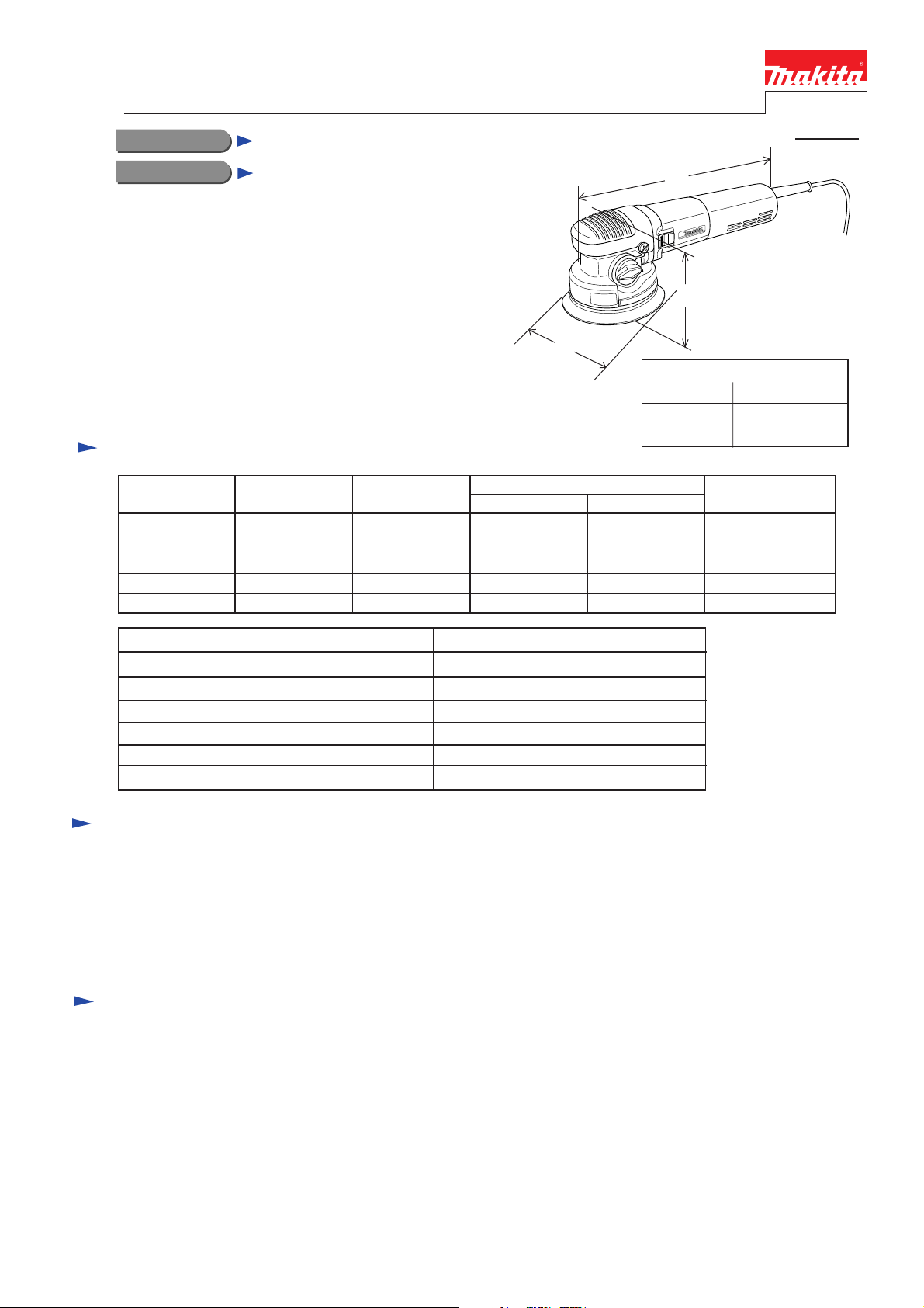
BO6040
150 mm Random Orbit Sander
W
L
H
Dimensions : mm ( " )
Width ( W )
Height ( H )
Length ( L )
150 (5-7/8)
132 (5-3/16)
316 (12-1/2)
Orbits per min. : (min -1= spm)
Orbit diameter : mm (")
Pad diameter : mm (")
Net weight :Kg (lbs )
Cord length : m ( ft )
1,600 - 5,800
3,200 - 11,600
180 - 670
5.5 ( 7/32)
150 ( 6 )
2.5 ( 8.2 )
2.7 ( 5.9 )
7.2
6.6
3.6
3.4
3.3
50 / 60
50 / 60
50 / 60
50 / 60
50 / 60
750 390 850
750 390 850
750 390 850
750 390 850
750 390 850
* Pad 150 (soft ) ........................................................... 1pc. (factory-attached to the machine)
* Abrasive disc 150-120 (Hook and loop type) ........... 1 pc.
* Hex wrench 6 ........................................................... 1 pc.
* Joint ........................................................................... 1 pc. ( only for European market)
* Pad 150 ( hard)
* - ditto - ( soft)
* - ditto - ( super soft)
* Abrasive disc 150 - 40, 60, 80, 120, 180, 240, 400
* Sanding cloth 150 - 100, 200, 800
* Sponge pad 150 ( hook and loop type)
* Felt pad 150 ( hook and loop type )
* Wool pad 150 ( hook and loop type )
* Side grip
This models is versatile random orbit sander for
professional use.
Due to the two mode selection,
"Forcible rotation mode" / "Free-rotation mode",
rough sanding, fine finishing and polishing can be done
only with this machine.
Oscillation rate per min.: spm = min-1
Rpm.of pad with Forcible-Rotation : rpm = min-1