Makita DGA701 User manual

DGA701
DGA901
EN Cordless Angle Grinder INSTRUCTION MANUAL 9
FR Meuleuse d’Angle sans Fil MANUEL D’INSTRUCTIONS 27
DE Akku-Winkelschleifer BETRIEBSANLEITUNG 47
IT Smerigliatrice angolare a
batteria ISTRUZIONI PER L’USO 67
NL Haakse accuslijpmachine GEBRUIKSAANWIJZING 87
ES Esmeriladora Angular
Inalámbrica
MANUAL DE
INSTRUCCIONES 106
PT Esmerilhadeira Angular a
Bateria MANUAL DE INSTRUÇÕES 126
DA Ledningsfri vinkelsliber BRUGSANVISNING 145
EL
164
TR KULLANMA KILAVUZU 185

2
1
2
3
Fig.1
1
2
Fig.2
1
Fig.3
1
Fig.4
1
2
Fig.5
1
Fig.6
Fig.7
1
2
3
Fig.8

3
1
2
Fig.9
1
2
Fig.10
1
Fig.11
1
2
Fig.12
1
4
2
3
Fig.13
2
1
Fig.14
1
2
3
4
Fig.15
1
2
3
Fig.16

4
1
2
4
3
Fig.17
1
Fig.18
12
Fig.19
Fig.20
1
2
3
4
Fig.21
1
2
3
4
ø45
ø78
ø78
5
Fig.22
1
Fig.23
1
Fig.24

5
1
Fig.25
1
2
4
5
6
3
Fig.26
Fig.27
1
2
Fig.28
15°
Fig.29
Fig.30
Fig.31
Fig.32

6
Fig.33
Fig.34
Fig.35
Fig.36
1
Fig.37
4
3
1
2
Fig.38
1
2
3
Fig.39

7
1
Fig.40
1
2
2
1
Fig.41
Fig.42
1
Fig.43
2
1
Fig.44
1
Fig.45

8
1
Fig.46
1
2
2
1
Fig.47
2
1
Fig.48
1
Fig.49
1
2
Fig.50

9ENGLISH
ENGLISH (Original instructions)
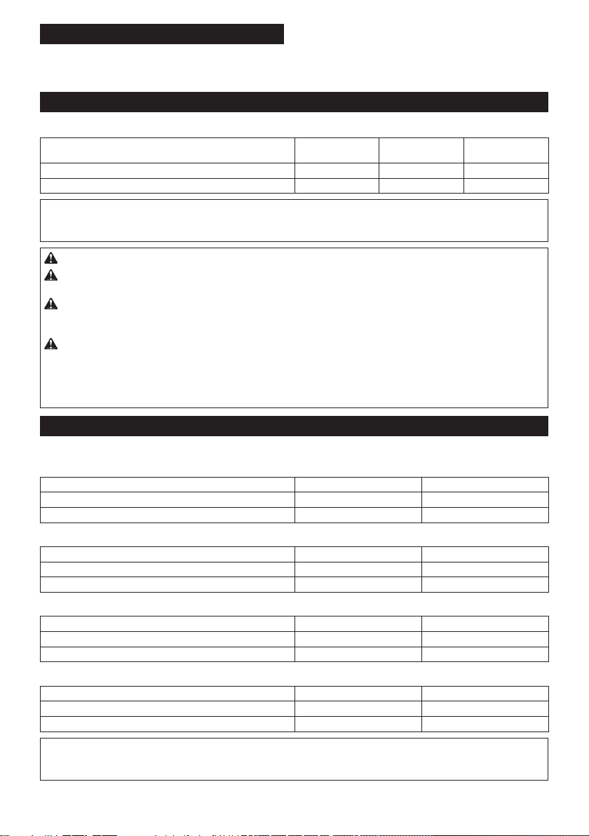
SPECIFICATIONS
Model: DGA701 DGA901
Applicable grinding wheel Max. wheel diameter 180 mm 230 mm
Max. wheel thickness 7.2 mm 6.5 mm
Max. wheel diameter 180 mm 230 mm
Max. wheel thickness 4.0 mm 3.2 mm
Applicable wire wheel brush Max. wheel diameter 150 mm 175 mm
Max. wheel thickness 20 mm
Spindle thread
Max. spindle length 26 mm
0 7,800 min-1 6,000 min-1
Overall length with BL1840B 499 mm
Net weight 5.0 - 6.0 kg 5.2 - 8.0 kg
D.C. 36 V
without notice.
-
est combinations, according to EPTA-Procedure 01/2014, are shown in the table.
Applicable battery cartridge and charger
BL1815N / BL1820B / BL1830B / BL1840B / BL1850B / BL1860B
Charger
DC18SH / DC18WC
•
WARNING: Only use the battery cartridges and chargers listed above.
Recommended cord connected power source
Portable power pack PDC01 / PDC1200
Symbols
meaning before use.
operations.
Ni-MH
Li-ion
Due to the presence of hazardous com-
ponents in the equipment, waste electrical
and electronic equipment, accumulators
on the environment and human health.
Do not dispose of electrical and electronic
appliances or batteries with household waste!
In accordance with the European Directive
on waste electrical and electronic equip-
ment and on accumulators and batteries
and waste accumulators and batteries,
as well as their adaptation to national law,
waste electrical equipment, batteries and
and delivered to a separate collection point
for municipal waste, operating in accor-
dance with the regulations on environmen-
tal protection.
crossed-out wheeled bin placed on the
equipment.

10 ENGLISH
Intended use
The tool is intended for grinding, sanding, wire brush-
ing, hole cutting and cutting of metal and stone materi-
als without the use of water.
Noise
Model Sound pressure
level (LpA) : (dB(A))
Sound power level
(LWA) : (dB(A))
Uncertainty (K) :
(dB(A))
DGA701 91 99 3
DGA901 91 99 3
NOTE:
NOTE:
WARNING: Wear ear protection.
WARNING: -
ue(s) depending on the ways in which the tool is used especially what kind of workpiece is processed.
WARNING: Be sure to identify safety measures to protect the operator that are based on an estimation
of exposure in the actual conditions of use (taking account of all parts of the operating cycle such as the
WARNING: Grinding thin sheets of metal or other easily vibrating structures with a large surface can
result in a total noise emission much higher (up to 15 dB) than the declared noise emission values.
Take the increased noise emission into consideration for both the risk assessment of noise exposure and
selecting adequate hearing protection.
Vibration
Work mode: surface grinding with normal side grip
Model
Vibration emission (ah, AG) : (m/s2)
Uncertainty (K) : (m/s2)
DGA701 7.5 1.5
DGA901 7.0 1.5
Work mode: surface grinding with anti vibration side grip
Model
Vibration emission (ah, AG) : (m/s2)
Uncertainty (K) : (m/s2)
DGA701 7.5 1.5
DGA901 7.5 1.5
Work mode: disc sanding with normal side grip
Model
Vibration emission (ah, DS) : (m/s2)
Uncertainty (K) : (m/s2)
DGA701 2.5 m/s2or less 1.5
DGA901 2.5 m/s2or less 1.5
Work mode: disc sanding with anti vibration side grip
Model
Vibration emission (ah, DS) : (m/s2)
Uncertainty (K) : (m/s2)
DGA701 2.5 m/s2or less 1.5
DGA901 2.5 m/s2or less 1.5
NOTE:
NOTE:

11 ENGLISH
WARNING:
value(s) depending on the ways in which the tool is used especially what kind of workpiece is processed.
WARNING: Be sure to identify safety measures to protect the operator that are based on an estimation
of exposure in the actual conditions of use (taking account of all parts of the operating cycle such as the
WARNING: The declared vibration emission value is used for main applications of the power tool. However if
EC Declaration of Conformity
For European countries only
to this instruction manual.
SAFETY WARNINGS
General power tool safety warnings
WARNING Read all safety warnings, instruc-
this power tool.
Save all warnings and instruc-
tions for future reference.
Cordless grinder safety warnings
Safety warnings common for grinding, sanding,
1. This power tool is intended to function as a
grinder, sander, wire brush, hole cutter or cut-
this power tool.
2. Operations such as polishing are not to be
performed with this power tool. Operations for
3. Do not convert this power tool to operate in
Such a con-
4. Do not use accessories which are not spe-
manufacturer.
safe operation.
5. The rated speed of the accessory must be at
least equal to the maximum speed marked on
the power tool. Accessories running faster than
6. The outside diameter and the thickness of your
accessory must be within the capacity rating
of your power tool.
7. The dimensions of the accessory mounting
-
ware of the power tool. Accessories that do not
match the mounting hardware of the power tool
8. Do not use a damaged accessory. Before each
use inspect the accessory such as abrasive
wheels for chips and cracks, backing pad for
cracks, tear or excess wear, wire brush for
loose or cracked wires. If power tool or acces-
sory is dropped, inspect for damage or install
an undamaged accessory. After inspecting and
installing an accessory, position yourself and
bystanders away from the plane of the rotating
accessory and run the power tool at maximum
no-load speed for one minute. Damaged acces-
time.
9. Wear personal protective equipment.
Depending on application, use face shield,
safety goggles or safety glasses. As appro-
priate, wear dust mask, hearing protectors,
gloves and workshop apron capable of stop-
ping small abrasive or workpiece fragments.
The dust mask or respirator must be capable
10. Keep bystanders a safe distance away from
work area. Anyone entering the work area
must wear personal protective equipment.
area of operation.
11. Hold the power tool by insulated gripping
surfaces only, when performing an operation
where the cutting tool may contact hidden
wiring. Contact with a "live" wire will also make
exposed metal parts of the power tool "live" and
could give the operator an electric shock.
12. Never lay the power tool down until the acces-
sory has come to a complete stop. The spinning
13. Do not run the power tool while carrying it at
your side. Accidental contact with the spinning

12 ENGLISH
14. Regularly clean the power tool’s air vents. The
motor’s fan will draw the dust inside the housing
and excessive accumulation of powdered metal
15.
materials. Sparks could ignite these materials.
16. Do not use accessories that require liquid
coolants. Using water or other liquid coolants
Kickback and related warnings:
Kickback is a sudden reaction to a pinched or snagged
-
-
trolled power tool to be forced in the direction opposite
entering into the pinch point can dig into the surface of
the material causing the wheel to climb out or kick out.
operator, depending on direction of the wheel’s move-
break under these conditions.
Kickback is the result of power tool misuse and/or
incorrect operating procedures or conditions and can be
1.
power tool and position your body and arms
to allow you to resist kickback forces. Always
use auxiliary handle, if provided, for maxi-
mum control over kickback or torque reaction
during start-up. The operator can control torque
reactions or kickback forces, if proper precautions
are taken.
2. Never place your hand near the rotating acces-
sory.
3. Do not position your body in the area where
power tool will move if kickback occurs.
Kickback will propel the tool in direction opposite
to the wheel’s movement at the point of snagging.
4. Use special care when working corners, sharp
edges, etc. Avoid bouncing and snagging the
accessory. Corners, sharp edges or bouncing
and cause loss of control or kickback.
5. Do not attach a saw chain woodcarving blade,
segmented diamond wheel with a peripheral
gap greater than 10 mm or toothed saw blade.
Such blades create frequent kickback and loss of
control.
-
1.
designed for the selected wheel. Wheels for
which the power tool was not designed cannot be
2. The grinding surface of centre depressed
wheels must be mounted below the plane of
the guard lip.
3. The guard must be securely attached to the
power tool and positioned for maximum safety,
so the least amount of wheel is exposed
towards the operator. The guard helps to protect
the operator from broken wheel fragments, acci-
dental contact with wheel and sparks that could
ignite clothing.
4. -
cations. For example: do not grind with the
are intended for peripheral grinding, side forces
shatter.
5.
of correct size and shape for your selected
wheel.
6. Do not use worn down wheels from larger
power tools. A wheel intended for larger power
tool is not suitable for the higher speed of a
7. When using dual purpose wheels always use
the correct guard for the application being
performed.
not provide the desired level of guarding, which
operations:
1. -
sive pressure. Do not attempt to make an
excessive depth of cut. Overstressing the wheel
or binding of the wheel in the cut and the possibil-
2. Do not position your body in line with and
behind the rotating wheel. When the wheel, at
-
3. When the wheel is binding or when interrupt-
tool and hold it motionless until the wheel
comes to a complete stop. Never attempt to
the wheel is in motion otherwise kickback may
occur. Investigate and take corrective action to
eliminate the cause of wheel binding.
4. Do not restart the cutting operation in the
workpiece. Let the wheel reach full speed and
carefully re-enter the cut.
walk up or kickback if the power tool is restarted in
the workpiece.
5. Support panels or any oversized workpiece to
minimize the risk of wheel pinching and kick-
back. Large workpieces tend to sag under their
own weight. Supports must be placed under the
workpiece near the line of cut and near the edge
of the workpiece on both sides of the wheel.
6. Use extra caution when making a “pocket cut”
into existing walls or other blind areas. The
-

13 ENGLISH
7. Do not attempt to do curved cutting.
Overstressing the wheel increases the loading and
8. Before using a segmented diamond wheel,
make sure that the diamond wheel has the
peripheral gap between segments of 10 mm or
less, only with a negative rake angle.
1. Use proper sized sanding disc paper. Follow
manufacturers recommendations, when
selecting sanding paper. Larger sanding paper
-
tearing of the disc or kickback.
operations:
1. Be aware that wire bristles are thrown by the
brush even during ordinary operation. Do not
overstress the wires by applying excessive
load to the brush.
penetrate light clothing and/or skin.
2.
brushing, do not allow any interference of the
wire wheel or brush with the guard. Wire wheel
and centrifugal forces.
Additional Safety Warnings:
1. When using depressed centre grinding wheels,
wheels.
2. NEVER USE Stone Cup type wheels with this
grinder. This grinder is not designed for these
3. Be careful not to damage the spindle, the
lock nut. Damage to these parts could result in
wheel breakage.
4. Make sure the wheel is not contacting the
workpiece before the switch is turned on.
5. Before using the tool on an actual workpiece,
let it run for a while. Watch for vibration or
wobbling that could indicate poor installation
or a poorly balanced wheel.
6. -
form the grinding.
7. Do not leave the tool running. Operate the tool
only when hand-held.
8. Do not touch the workpiece immediately after
operation; it may be extremely hot and could
burn your skin.
9. Do not touch accessories immediately after
operation; it may be extremely hot and could
burn your skin.
10. Observe the instructions of the manufacturer
for correct mounting and use of wheels.
Handle and store wheels with care.
11. Do not use separate reducing bushings or
adaptors to adapt large hole abrasive wheels.
12.
13.
hole wheel, ensure that the thread in the wheel
is long enough to accept the spindle length.
14. Check that the workpiece is properly
supported.
15. Pay attention that the wheel continues to
16. If working place is extremely hot and humid,
or badly polluted by conductive dust, use a
short-circuit breaker (30 mA) to assure opera-
tor safety.
17. Do not use the tool on any materials contain-
ing asbestos.
18.
the dust collecting wheel guard if required by
domestic regulation.
19. Cutting discs must not be subjected to any
lateral pressure.
20. Do not use cloth work gloves during operation.
causes tool breakage.
21. Before operation, make sure that there is no
buried object such as electric pipe, water pipe
or gas pipe in the workpiece.
cause an electric shock, electrical leakage or gas
leak.
22. If a blotter is attached to the wheel, do not
remove it. The diameter of the blotter must be
23. Before installing a grinding wheel, always
check that the blotter part does not have any
abnormalities such as chips or cracks.
24. Tighten the lock nut properly. Overtightening
SAVE THESE INSTRUCTIONS.
WARNING: DO NOT let comfort or familiarity
with product (gained from repeated use) replace
strict adherence to safety rules for the subject
product. MISUSE or failure to follow the safety
rules stated in this instruction manual may cause
serious personal injury.
Important safety instructions for
battery cartridge
1. Before using battery cartridge, read all instruc-
tions and cautionary markings on (1) battery
charger, (2) battery, and (3) product using
battery.
2. Do not disassemble or tamper with the battery
cartridge.
or explosion.
3. If operating time has become excessively
shorter, stop operating immediately. It may
result in a risk of overheating, possible burns
and even an explosion.
4. If electrolyte gets into your eyes, rinse them
out with clear water and seek medical atten-
tion right away. It may result in loss of your
eyesight.

14 ENGLISH
5. Do not short the battery cartridge:
Do not touch the terminals with any con-
ductive material.
Avoid storing battery cartridge in a con-
tainer with other metal objects such as
nails, coins, etc.
Do not expose battery cartridge to water
or rain.
A battery short can cause a large current
breakdown.
6. Do not store and use the tool and battery car-
tridge in locations where the temperature may
reach or exceed 50 °C (122 °F).
7. Do not incinerate the battery cartridge even if
it is severely damaged or is completely worn
8. Do not nail, cut, crush, throw, drop the battery
cartridge, or hit against a hard object to the
battery cartridge.
9. Do not use a damaged battery.
10. The contained lithium-ion batteries are subject
to the Dangerous Goods Legislation require-
ments.
forwarding agents, special requirement on pack-
aging and labeling must be observed.
-
ing an expert for hazardous material is required.
national regulations.
around in the packaging.
11. When disposing the battery cartridge, remove
it from the tool and dispose of it in a safe
place. Follow your local regulations relating to
disposal of battery.
12. Use the batteries only with the products
Installing the batteries to
-
13. If the tool is not used for a long period of time,
the battery must be removed from the tool.
14. During and after use, the battery cartridge may
take on heat which can cause burns or low
temperature burns. Pay attention to the han-
dling of hot battery cartridges.
15. Do not touch the terminal of the tool imme-
diately after use as it may get hot enough to
cause burns.
16. Do not allow chips, dust, or soil stuck into the
terminals, holes, and grooves of the battery
cartridge.
-
17. Unless the tool supports the use near
high-voltage electrical power lines, do not use
the battery cartridge near high-voltage electri-
cal power lines.
18. Keep the battery away from children.
SAVE THESE INSTRUCTIONS.
CAUTION: Only use genuine Makita batteries.
Use of non-genuine Makita batteries, or batteries that
charger.
Tips for maintaining maximum
battery life
1. Charge the battery cartridge before completely
discharged. Always stop tool operation and
charge the battery cartridge when you notice
less tool power.
2. Never recharge a fully charged battery car-
tridge. Overcharging shortens the battery
service life.
3. Charge the battery cartridge with room tem-
perature at 10 °C - 40 °C (50 °F - 104 °F). Let
a hot battery cartridge cool down before
charging it.
4. When not using the battery cartridge, remove
it from the tool or the charger.
5. Charge the battery cartridge if you do not use
it for a long period (more than six months).
Important safety instructions for
wireless unit
1. Do not disassemble or tamper with the wire-
less unit.
2. Keep the wireless unit away from young chil-
dren. If accidentally swallowed, seek medical
attention immediately.
3. Use the wireless unit only with Makita tools.
4. Do not expose the wireless unit to rain or wet
conditions.
5. Do not use the wireless unit in places where
the temperature exceeds 50 °C (122 °F).
6. Do not operate the wireless unit in places
where medical instruments, such as heart
pace makers are nearby.
7. Do not operate the wireless unit in places
where automated devices are nearby. If oper-
or error.
8. Do not operate the wireless unit in places
under high temperature or places where
static electricity or electrical noise could be
generated.
9. The wireless unit can produce electromagnetic
user.
10. The wireless unit is an accurate instrument. Be
careful not to drop or strike the wireless unit.
11. Avoid touching the terminal of the wireless
unit with bare hands or metallic materials.
12. Always remove the battery on the product
when installing the wireless unit into it.

15 ENGLISH
13. When opening the lid of the slot, avoid the
place where dust and water may come into the
slot. Always keep the inlet of the slot clean.
14. Always insert the wireless unit in the correct
direction.
15. Do not press the wireless activation button
on the wireless unit too hard and/or press the
button with an object with a sharp edge.
16. Always close the lid of the slot when
operating.
17. Do not remove the wireless unit from the slot
while the power is being supplied to the tool.
unit.
18. Do not remove the sticker on the wireless unit.
19. Do not put any sticker on the wireless unit.
20. Do not leave the wireless unit in a place where
static electricity or electrical noise could be
generated.
21. Do not leave the wireless unit in a place sub-
ject to high heat, such as a car sitting in the
sun.
22. Do not leave the wireless unit in a dusty or
powdery place or in a place corrosive gas
could be generated.
23. Sudden change of the temperature may bedew
the wireless unit. Do not use the wireless unit
until the dew is completely dried.
24. When cleaning the wireless unit, gently wipe
with a dry soft cloth. Do not use benzine, thin-
ner, conductive grease or the like.
25. When storing the wireless unit, keep it in the
supplied case or a static-free container.
26. Do not insert any devices other than Makita
wireless unit into the slot on the tool.
27. Do not use the tool with the lid of the slot dam-
aged.
cause malfunction.
28. Do not pull and/or twist the lid of the slot more
than necessary.
from the tool.
29. Replace the lid of the slot if it is lost or
damaged.
SAVE THESE INSTRUCTIONS.
FUNCTIONAL DESCRIPTION
CAUTION: Always be sure that the tool is
before adjusting or checking function on the tool.
Installing or removing battery cartridge
CAUTION:
installing or removing of the battery cartridge.
CAUTION: Hold the tool and the battery car-
cartridge.
Fig.1: 1.2. Button 3.
while sliding the button on the front of the cartridge.
CAUTION: Always install the battery cartridge
fully until the red indicator cannot be seen. If not,
CAUTION: Do not install the battery cartridge
forcibly.
Indicating the remaining battery capacity
Only for battery cartridges with the indicator
Fig.2: 1. Indicator lamps 2. Check button
-
light up for a few seconds.
Indicator lamps Remaining
capacity
Lighted Blinking
75% to 100%
50% to 75%
25% to 50%
0% to 25%
Charge the
malfunctioned.

16 ENGLISH
NOTE: Depending on the conditions of use and the
NOTE:
Tool / battery protection system
Fig.3: 1.
Overload protection
When the tool is operated in a manner that causes it to
become overloaded. Then turn the tool on to restart.
Overheat protection
When the tool or batteries is overheated, the tool stops automati-
-
tion, let the tool and batteries cool before turning the tool on again.
On Blinking
Overdischarge protection
On Blinking
Protections against other causes
Take all the following steps to clear the causes, when the tool
1.
Shaft lock
WARNING: Never actuate the shaft lock when
the spindle is moving.
the tool damage.
Press the shaft lock to prevent spindle rotation when
installing or removing accessories.
Fig.4: 1. Shaft lock
Switch action
CAUTION: Before installing the battery car-
tridge into the tool, always check to see that the
switch lever actuates properly and returns to the
"OFF" position when released.
CAUTION: For your safety, this tool is
tool from unintended starting. NEVER use the tool
if it runs when you simply pull the switch lever
to our authorized service center for proper repairs
BEFORE further usage.
CAUTION: Do not pull the switch lever hard
This can cause
switch breakage.
CAUTION: NEVER tape down or defeat pur-
switch lever.
To stop the tool, release the switch lever.
Fig.5: 1.2. Switch lever
Automatic speed change function
Fig.6: 1. Mode indicator
Mode indicator status Operation mode
On
High speed mode
High torque mode
This tool has "high speed mode" and "high torque
depending on the work load. When mode indicator
lights up during operation, the tool is in high torque
mode.
Accidental re-start preventive
function
ON, the tool does not start.

17 ENGLISH
Active Feedback sensing Technology
cause of sudden drop in the rotation speed, and then
turn the tool on.
Soft start feature
Soft start feature reduces starting reaction.
Electric brake
the switch still on.
ASSEMBLY
CAUTION: Always be sure that the tool is
before adjusting or checking function on the tool.
Installing side grip (handle)
CAUTION: Always be sure that the side grip is
installed securely before operation.
Fig.7
Installing or removing wheel guard
WARNING: When using a depressed center
the closed side of the guard always points toward
the operator.
WARNING:
/ diamond wheel, be sure to use only the special
For tool with locking screw type
wheel guard
Mount the wheel guard with the protrusions on the wheel guard
band aligned with the notches on the bearing box. Then rotate
the wheel guard to such an angle that it can protect the opera-
To remove wheel guard, follow the installation proce-
dure in reverse.
Fig.8: 1. Wheel guard 2. Bearing box 3. Screw
For tool with clamp lever type wheel
guard
Loosen the nut, and then pull the lever in the direction
of the arrow.
Fig.9: 1. Nut 2. Lever
Mount the wheel guard with the protrusions on the
wheel guard band aligned with the notches on the bear-
ing box. Then rotate the wheel guard to such an angle
that it can protect the operator according to work.
Fig.10: 1. Wheel guard 2. Bearing box
Fig.11: 1. Wheel guard
lever in direction of the arrow to fasten the wheel guard. If
the lever is too tight or too loose to fasten the wheel guard,
open the lever and then loosen or tighten the nut using the
Fig.12: 1. Nut 2. Lever
To remove wheel guard, follow the installation proce-
dure in reverse.
Installing or removing depressed
Optional accessory
WARNING: When using a depressed center
on the tool so that the closed side of the guard
always points toward the operator.
WARNING: Make sure that the mounting part
result in the dangerous vibration.
the straight part at the bottom of the spindle.
Fig.13: 1. Lock nut 2. Depressed center wheel
3.4. Mounting part
that the spindle cannot revolve, then use the lock nut
Fig.14: 1. Lock nut wrench 2. Shaft lock
To remove the wheel, follow the installation procedure
in reverse.
Optional accessory
WARNING: Always use supplied guard when
Wheel can shatter during
use and guard helps to reduce chances of personal
Fig.15: 1. Lock nut 2.3. Back up pad
4.
use back up pad over wheel.

18 ENGLISH
Installing or removing abrasive disc
Optional accessory
Fig.16: 1. Sanding lock nut 2. Abrasive disc
3.
1. Mount the rubber pad onto the spindle.
2. -
ing lock nut onto the spindle.
3.
tighten the sanding lock nut clockwise with the lock nut
wrench.
To remove the disc, follow the installation procedure in
reverse.
NOTE:-
Installing or removing Ezynut
Optional accessory
Only for tools with M14 spindle thread.
Fig.17: 1.2. Abrasive wheel 3.
4. Spindle
abrasive wheel clockwise as far as it turns.
Fig.18: 1. Shaft lock
counterclockwise.
NOTE:
as the arrow points the notch. Otherwise a lock nut
wrench is required to loosen it. Insert one pin of the
Fig.19: 1. Arrow 2. Notch
Fig.20
wheel
Optional accessory
WARNING:
/ diamond wheel, be sure to use only the special
WARNING:
grinding.
lock nut onto the spindle.
Fig.21: 1. Lock nut 2.-
mond wheel 3.4. Wheel guard
For Australia and New Zealand
Fig.22: 1. Lock nut 2.3. Abrasive
4. Inner
5. Wheel guard for abrasive cut-
Installing wire cup brush
Optional accessory
CAUTION: Do not use brush that is damaged,
or which is out of balance. Use of damaged brush
broken brush wires.
spindle.
brush onto spindle and tighten with supplied wrench.
Fig.23: 1. Wire cup brush
Installing wire wheel brush
Optional accessory
CAUTION: Do not use wire wheel brush that
is damaged, or which is out of balance. Use of
damaged wire wheel brush could increase potential
CAUTION: ALWAYS use guard with wire
inside guard. Wheel can shatter during use and
spindle.
brush onto spindle and tighten with the wrenches.
Fig.24: 1. Wire wheel brush
Installing hole cutter
Optional accessory
spindle.
hole cutter onto the spindle, and tighten it with the sup-
plied wrench.
Fig.25: 1. Hole cutter
Installing dust collecting wheel
guard for grinding
Optional accessory
planing concrete surface.
CAUTION: Dust collecting wheel guard for
grinding is only for use in planing concrete sur-
face with a cup-type diamond wheel. Do not use
this guard with any other cutting accessory or for
any other purpose.
CAUTION: Before operation, make sure that
a vacuum cleaner is connected to the tool and
turned on.

19 ENGLISH
Place the tool upside down and install the dust collect-
ing wheel guard.
tighten the lock nut onto the spindle.
Fig.26: 1. Lock nut 2.
3.4. Inner
5. Dust collecting wheel guard
6. Bearing box
NOTE:-
lecting wheel guard, refer to the manual of the dust
collecting wheel guard.
Installing dust collecting wheel
Optional accessory
cutting stone materials.
Fig.27
NOTE:-
lecting wheel guard, refer to the manual of the dust
collecting wheel guard.
Connecting a vacuum cleaner
Optional accessory
WARNING: Never vacuum metal particles
created by grinding/cutting/sanding operation.
cleaner.
use a dust collecting wheel guard and a vacuum cleaner.
collecting wheel guard for assembling and using it.
Fig.28: 1. Dust collecting wheel guard 2. Hose of
the vacuum cleaner
OPERATION
WARNING: It should never be necessary to
force the tool. The weight of the tool applies ade-
could cause dangerous wheel breakage.
WARNING: ALWAYS replace wheel if tool is
dropped while grinding.
WARNING: NEVER hit the workpiece with the
wheel.
WARNING: Avoid bouncing and snagging
the wheel, especially when working corners,
sharp edges etc. This can cause loss of control and
kickback.
WARNING: NEVER use tool with wood cutting
blades and other saw blades. Such blades when
CAUTION: Never switch on the tool when it
is in contact with the workpiece, it may cause an
injury to operator.
CAUTION: Always wear safety goggles or a
face shield during operation.
CAUTION:
the tool and wait until the wheel has come to a
complete stop before putting the tool down.
CAUTION:
one hand on housing and the other on the side
grip (handle).
NOTE: A dual purpose wheel can be used for both
grinding operation, and refer to the "Operation with
operation.
Grinding and sanding operation
Fig.29
workpiece.
In general, keep the edge of the wheel or disc at an
angle of about 15° to the workpiece surface.
During the break-in period with a new wheel, do not
the workpiece. Once the edge of the wheel has been
forward and backward direction.
Usage example: operation with cup-type diamond wheel
Fig.30
diamond wheel to the workpiece surface.
diamond wheel
Optional accessory
WARNING: Do not "jam" the wheel or apply
excessive pressure. Do not attempt to make an
excessive depth of cut. Overstressing the wheel
of kickback, wheel breakage and overheating of the
WARNING: Do not start the cutting operation
in the workpiece. Let the wheel reach full speed
and carefully enter into the cut moving the tool
forward over the workpiece surface. The wheel
started in the workpiece.
WARNING: During cutting operations, never
change the angle of the wheel. Placing side pres-
the wheel to crack and break, causing serious per-
WARNING: A diamond wheel shall be oper-
ated perpendicular to the material being cut.

20 ENGLISH
wheel
Fig.31
Usage example: operation with diamond wheel
Fig.32
Operation with wire cup brush
Optional accessory
CAUTION: Check operation of brush by run-
ning tool with no load, insuring that no one is in
front of or in line with brush.
NOTICE: Avoid applying too much pressure
which causes over bending of wires when using
the wire cup brush.
breakage.
Usage example: operation with wire cup brush
Fig.33
Operation with wire wheel brush
Optional accessory
CAUTION: Check operation of wire wheel
brush by running tool with no load, insuring that
no one is in front of or in line with the wire wheel
brush.
NOTICE: Avoid applying too much pressure
which causes over bending of wires when
using wire wheel brush.
breakage.
Usage example: operation with wire wheel brush
Fig.34
Operation with hole cutter
Optional accessory
CAUTION: Check operation of the hole cutter
by running the tool with no load, insuring that no
one is in front of the hole cutter.
NOTICE: Do not tilt the tool during operation. It
Usage example: operation with hole cutter
Fig.35
WIRELESS ACTIVATION
FUNCTION
What you can do with the wireless
activation function
The wireless activation function enables clean and com-
Fig.36
To use the wireless activation function, prepare follow-
• A vacuum cleaner which supports the wireless
activation function
The overview of the wireless activation function
procedures.
1. Installing the wireless unit
2. Tool registration for the vacuum cleaner
3. Starting the wireless activation function
Installing the wireless unit
Optional accessory
CAUTION:
surface when installing the wireless unit.
NOTICE:
Clean the dust and dirt on the tool before
installing the wireless unit.
malfunction if it comes into the slot of the wireless unit.
NOTICE:
To prevent the malfunction caused by static,
touch a static discharging material, such as a metal part
of the tool, before picking up the wireless unit.
NOTICE:
When installing the wireless unit, always
be sure that the wireless unit is inserted in the cor-
rect direction and the lid is completely closed.
1.
Fig.37: 1. Lid
2. Insert the wireless unit to the slot and then close
the lid.
with the recessed portions on the slot.
Fig.38: 1. Wireless unit 2.3. Lid
4.
The hooks on the back of the lid will lift the wireless unit
Fig.39: 1. Wireless unit 2. Hook 3. Lid
After removing the wireless unit, keep it in the supplied
case or a static-free container.
NOTICE: Always use the hooks on the back of
the lid when removing the wireless unit. If the
hooks do not catch the wireless unit, close the lid
Other manuals for DGA701
2
This manual suits for next models
2
Table of contents
Languages:
Other Makita Grinder manuals

Makita
Makita DGA404 User manual

Makita
Makita DGA404 Manual

Makita
Makita M9511 User manual

Makita
Makita 9564 User manual

Makita
Makita GA036G User manual

Makita
Makita GA6040C User manual

Makita
Makita GD0800C User manual

Makita
Makita GA4040 User manual

Makita
Makita GA5030RSP1 User manual

Makita
Makita 9561CR User manual