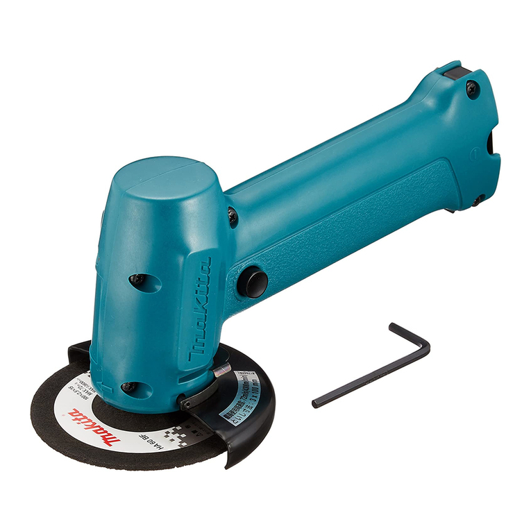
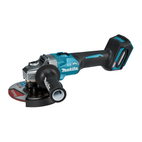
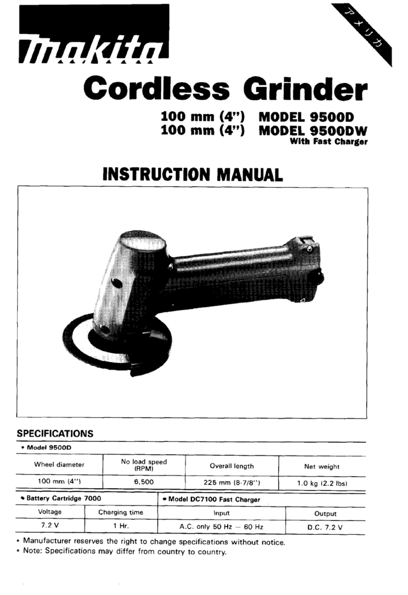
Makita DGA417 Operating instructions

November 2017
Ver.1
CORDLESS ANGLE GRINDER
DG A 4 1 7/ DG A 4 6 7/ DGA517/
DGA418/ DGA468/ DGA518
REPAIR MANUAL

2 / 23
1CONTENTS
1CONTENTS.................................................................................................................................................................................2
2CAUTION....................................................................................................................................................................................3
3NECESSARY REPAIRING TOOLS...........................................................................................................................................3
4TIGHTENING TORQUE SPECIFICATIONS............................................................................................................................3
5LUBRICANT AND ADHESIVE APPLICATION......................................................................................................................4
6REPAIR ........................................................................................................................................................................................5
6-1 Rotor , Ball bearings 629LLB / 607LLB, Spiral bevel gear 10............................................................................................5
6-1-1 Disassembly ................................................................................................................................................................5
6-1-2 Assembly.....................................................................................................................................................................7
6-2 Spiral bevel gear 37, Bearing box section............................................................................................................................9
6-2-1 Disassembly ................................................................................................................................................................9
6-2-2 Assembly...................................................................................................................................................................12
6-3 Shaft lock mechanism........................................................................................................................................................15
6-3-1 Disassembly ..............................................................................................................................................................15
6-3-2 Assembly...................................................................................................................................................................15
6-4 Assembly of Stator complete .............................................................................................................................................16
7CIRCUIT DAIGRAM................................................................................................................................................................17
8WIRING DIAGRAM.................................................................................................................................................................18
8-1 Wiring in Motor housing L before setting Dial section......................................................................................................18
8-2 Wiring in Motor housing L ................................................................................................................................................19
9TROUBLESHOOTING.............................................................................................................................................................20
9-1 Note in Repairing...............................................................................................................................................................20
9-2 Test for the trouble on Controller .......................................................................................................................................20
9-3 Flowchart of Troubleshooting............................................................................................................................................21
9-4 Wireless activation (for model DGA418/ DGA468/ DGA518).........................................................................................22
9-4-1 Step1: Preparation for Wireless activation.................................................................................................................22
9-4-2 Step2: Tool registration..............................................................................................................................................22
9-4-3 Step3 : Checking wireless activation.........................................................................................................................23
9-4-4 Check target in trouble ..............................................................................................................................................23

3 / 23
CAUTION
Repair the machine in accordance with “Instruction manual” or “Safety instructions”.
Follow the instructions described below in advance before repairing:
・Wear gloves.
・In order to avoid wrong reassembly, draw or write down where and how the parts are assembled, and what the parts are.
It is also recommended to have boxes ready to keep disassembled parts by group.
・Handle the disassembled parts carefully. Clean and wash them properly.
2NECESSARY REPAIRING TOOLS
Code No.
Description
Use for
1R003 Retaining ring pliers ST-2N Assembling / Disassembling Ring spring 11
1R026
Bearing setting pipe 16-8.2
Removing Ball bearing 6201DDW
1R028
Bearing Setting Pipe 20-12.2
Press fitting Spindle/A/B
1R029
Bearing Setting Pipe 23-15.2
Press fitting Spiral bevel gear 37
1R032
Bearing Setting Plate 8.2
Press fitting Ball bearing 607LLB
1R033 Bearing Setting Plate 10.2 Press fitting Ball bearing 607LLB
1R038 Armature Holder 32 Set Holding Rotor when removing / assembling M6 Hex
nut
1R045
Gear Extractor (large)
Separating Rotor from Gear housing cover
1R164
Ring Sprig Setting ToolA
Press fitting Ball bearing 6201DDW
1R212-A Tip for Retaining Ring Pliers Attaching to 1R003
1R212
-
B
Plate Set (with Screws)
Attaching to 1R003
1R220 Ratchet Head 9.5 Attaching to 1R254 for loosening / tightening M6 Hex
nut
1R222
SocketAdapter Attaching to 1R254 for tightening M6 Hex nut
1R248 Round Bar for Arbor 22-100 Removing Felt ring 16 from Bearing box
1R252
Round Bar forArbor 30-100
Press fitting Felt ring 16 to Bearing box
1R254
Torque Wrench shaft 2-6N.M
Tightening M6 Hex nut
1R258
V
Block
Supporting Bearing box when removing Spindle/A/B
1R268
Spring Pin Extractor M3 Removing Shoulder pin 4 from Pin cap of Shaft lock
1R269 Bearing Extractor Removing Ball bearings 607LLB / 696ZZ
1R284
Round Bar forArbor 22-100
Removing Spindle/A/B from Spiral bevel gear 37
1R291
Retaining Ring S and R Pliers
Removing / Mounting Retaining rings R-32 / R-26
3TIGHTENINGTORQUE SPECIFICATIONS
No. Parts to fasten Fastener
Tightening torque
(N・m)
1 Rotor M6 Hex nut M6 Hex nut 4.9~5.9

4 / 23
4LUBRICANTAND ADHESIVE APPLICATION
Item of Lubricant
Amount of Grease
MAKITAGrease R No.00 9 g to Gear room, and a little to O ring 26
Fig. 1
9g

5 / 23
5REPAIR
Caution: Battery has to be removed, before repairing for your safety.
5-1 Rotor , Ball bearings 629LLB / 607LLB, Spiral bevel gear 10
5-1-1 Disassembly
Fig. 2
1Unscrewing four 4x30 Tapping screws [1], separate
Gear housing [2].
Fig. 3
2Fitting slotted head screwdriver [3] to the notch [2]
of Gear housing cover [1], remove Gear housing
cover [1], twisting the screwdriver [3].
So, Rotor [4] comes out together with Gear housing
cover [1].
Fig. 4
3Fix Rotor [1] with 1R038 and Vise.Applying Eye
wrench 10 [2] to M6 Hex nut [3], turn Eye wrench
10 [2] counter clockwise.
Now, Spiral bevel gear 10 [4] is removed from
Rotor [1].
[2]
[1]
[3]
[1]
[4]
[1]
[1]
[2]
[3]
[4]
[4]
[3]
[1]
1R038
[2]
[2]
[1]
[1]

6 / 23
Fig. 5
4Applying 1R045 to Gear housing cover [1] and
shaft of Rotor [2], turn the handle.
Now, Rotor [2] is separated from Gear housing
cover[1].
Fig. 6
5Ball bearing 629LLB [2] can be removed from
Gear housing cover [1], by pushing it with finger.
Fig. 7
6Applying 1R269 to Ball bearing 607LLB and shaft
of Rotor [1], turn the handle.
Now, Ball bearing 607LLB [2] is removed from
Rotor [1]
1R045
[1]
[2]
[2]
[1]
[1]
[2]
[2]
[1]
[2]
1R269
[1]
[2]
[1]

7 / 23
5-1-2 Assembly
Fig. 8
7
Rotor When handling or storing Rotors,
therefore, protect Rotors from deterioration
due to the magnetic force as follows. Be sure
to provide a proper distance between Rotors
to protect from:
•Demagnetization by contact of Rotors
•Scratches on Rotor periphery, damage of
Fan and internal crack of Rotor by strong
collision of Rotors.
Also be sure to remove metal particles
attached on Rotor surface, which will cause
unusual noise and trouble.
Fig. 9
8Assemble Ball bearing 629LLB, by pushing into
Bearing box portion of Gear housing cover [1]
Fig. 10
9Put Gear housing cover on 1R033, aligning the Ball
bearing 629LLB in Fig. 9 to center hole of 1R033.
And stand Rotor [1] on Gear housing cover
inserting into the Ball bearing 629LLB
And setting Ball bearing 607LLB to shaft of Rotor
[1],put 1R032 on the Ball bearing 607LLB, and
press with Arbor press, until it stops.
Tips
In case of precisely assembled Ball bearing 607LLB,
shaft of Rotor [1] protrudes by 1.6 mm from Ball
bearing 607LLB.
1R033
1R032
[1]
[2]
1.6 mm
[2]
[1]
[1]
[2]
[1]

8 / 23
Fig. 11
10 Fixing Rotor with 1R038 and vise, set Spiral bevel
gear 10 [2] to Rotor, passing shaft of Rotor [1]
through Spiral bevel gear 10 [2].
11 Pre-setting fastening torque of 1R254 to
4.9~5.9N.m, attach 1R220, 1R222, Bit adapter
assembly and Socket bit 10 to 1R254.
12 And turn M6 Hex nut [5] with the above 1R254
clockwise until it stops. Now, assemble of Rotor
section has been finished.
Fig. 12
13 Mount Gear housing cover together with Rotor to
Motor housing, facing the notch [2] portion to the
same side to Switch lever [4].
14 Mount Gear housing facing Spindle/A to the same
side to Switch lever [4].
Note
Be careful, not to pinch your finger between Motor
housing and Gear housing cover or Fan of Rotor
which are dragged toward Stator in Motor housing by
extremely strong magnet force, when assembling
Gear housing cover to Motor housing.
1R254
1R220
1R222
1R038
[3]
[4]
[1]
[2]
[5]
[6]
[1]
[2]
[3]
[4]

9 / 23
5-2 Spiral bevel gear 37, Bearing box section
5-2-1 Disassembly
※No need to disassemble Motor section to repair Spiral bevel gear 37, Bearing box section.
Fig. 13
1Unscrewing four M4 x 14 Pan head screws,
separate Bearing box from Gear housing.
Fig. 14
2Applying 1R269 to Ball bearing 696ZZ and
Spindle/A/B, turn Handle of 1R269.
3Now, Ball bearing 696ZZ [1] has removed from
Spindle A/B.
Fig. 15
4Attaching 1R212-B and 1R212-A to 1R003,
remove Ring spring 11[1] with 1R003.
[2]
[1]
[1]
1R269
[1]
[1]
1R212-A
1R003
1R212-B
[1]

10 / 23
Fig. 16
5Put Bearing box [1] on 1R258, paying attention to
the following points.
Note
・The protrusion, circled with red dot line, has to be
positioned, keeping distance from both of 1R258.
・Lead flange/A/B [3] has not to contact to 1R258
when it is pushed out together with Spindle/A [2].
6Putting 1R032 on Spiral bevel gear 37 [4], give
shock to 1R032 withArbor press. So, Spindle/Ais
shifted from the position where it is.
Fig. 17
7Applying 1R284 to Spindle/A/B [1], press with
Arbor press. So, Spindle/A/B [1] is removed from
Bearing box, and Gear section is disassembled as
follows.
・Spindle/A/B [1]
・Lead flange/A/B [2]
・Bearing box [3]
・Spiral bevel gear 37 [4]
As for disassembly of Lead flange/A/B [2] from
Spindle/A [1], see Fig. 21.
Fig. 18
8First, remove Retaining ring R-32 from Bearing
box, using 1R291 in order to disassemble Bearing
box section.
1R258
[1]
[3]
[1]
[2]
1R032
[4]
1R284
1R258
[1]
[2]
[3]
[4]
[1]
1R291
[1]

11 / 23
Fig. 19
9Applying 1R026 to Ball bearing 6201DDW [1],
press 1R026 with Arbor press, so, Ball bearing
6201DDW [1] is removed from Bearing box.
Tips
Do not reuse the Ball bearing 6201DDW [1], because
it has been damaged in the step of Fig. 16.
Fig. 20
10 Remove Felt ring 16 with 1R248.
Fig. 21
11 Removing Retaining ring R-26 [1] with 1R291,
disassemble Lead flange/A/B [2] from
Spindle/A [3].
1R026
[1]
[1]
1R248
[1]
1R291
[1]
[2]
[1]
[2]
[3]

12 / 23
5-2-2 Assembly
Fig. 22
1Pass Spindle/A [2] through Lead flange/A/b [1].
And then, secure Lead flange/A/B [1] with
Retaining ring R-26 [3].
Fig. 23
2Push Felt ring 16 [1] with 1R252 and Arbor press,
until it stops.
Fig. 24
3When using 1R164, apply its small diameter
(30mm) side, marked with to Ball bearing
6201DDW [1].
And press fit withArbor press until its stops.
Now, Ball bearing 621DDW [1] has been mounted
to Bearing box.
Tips
Mount fresh Ball bearing 6201DDW [1], in stead of
removed one..
1R291
[2]
[1]
[3]
1R252
[1]
1R164
[1]

13 / 23
Fig. 25
4Mount Retaining ring R-32 [1] with 1R291.
Fig. 26
5Accepting Ball bearing 6201DDW, assembled in
the step of Fig. 24, with 1R028, stand Spindle/A[1]
inserting into the Ball bearing 6201DDW.
6Press Spindle/A [1] with Arbor press. So, the
Spindle has been mounted to Bearing box section.
Fig. 27
7Putting Spiral bevel gear 37 [1] on 1R291, insert
Spindle/A [2] into shaft hole of Spiral bevel
gear 37 [1].
8Press Spindle/A/B [2] with Arbor press.
So, Spiral bevel gear 37 [1] has been press fitted to
Spindle/A [2].
1R291
[1]
[1]
1R028
1R029
[1]
[2]

14 / 23
Fig. 28
9Attaching 1R212-B and 1R212-A to 1R003, mount
Ring spring 11 [1] with the 1R003.
Fig. 29
10 Press fit Ball bearing 696ZZ with Arbor press.
Now, Gear and Bearing box section has been
assembled.
1R212-A
1R003
1R212-B
[1]
[1]

15 / 23
Shaft lock mechanism
5-2-3 Disassembly
1Separate Gear housing from Motor housing. as shown in Fig. 2.
Fig. 30
2Disassemble Bearing box [2] unscrewing four
M4x14 Pan head screws [1].
Fig. 31
3Applying 1R268 to Shoulder pin 4 [1], strike
1R268 with Hammer.
Now, Shoulder pin 4 [1] has Now, Shoulder pin 4
[1] has been removed.
Fig. 32
4Consequently, Shaft lock mechanism is
disassembled as shown in photograph to left.
O Ring 5 [1]
Shoulder pin 4 [2]
Compression spring 8 [3]
Pin cap [4] (Do not reuse the removed one.)
Chip [5] scraped from Pin cap [4]
5-2-4 Assembly
1Fresh Pin cap has to be mounted. Because, the hole of the removed Pin cap [4] has got too big to accept Shoulder
pin 4 [2].
2The chip scraped from Pin cap [4] has to be removed from Shoulder pin 4 [2] before assembling.
[2]
[2]
[1]
[1]
[1]
[2]
[3]
[4]
[5]
1R268
[1]

16 / 23
5-3 Assembly of Stator complete
Fig. 33
1Fitting two Notches [2] of Stator complete [1] to rib
formed protrusions [4] of Motor housing L [3],
assemble Stator complete.
Tips
Stator complete [1] has to be so mounted that its
Terminal portion [5] is located to the position shown
in the photograph to left.
[2]
[4]
[5]
[1]
[3]

17 / 23
6CIRCUIT DAIGRAM
Red (AWG: #14)
Black
(AWG: #14)
+
AS
-
Terminal
Yellow (AWG: #22)
Flag receptacle
(
with lock #250, t=0.8
)
orange white, blue
(AWG: #14 for each)
red, white, yellow, blue, black,
green
Stator
Flag receptacle
(with
lock#187,t=0.8)
Noise
suppressor
black, white
(AWG: #16 for
each)
Dial section
red, blue, white
(AWG: #24 for each)
Connector
red, black, white
(AWG: #28 for each)
red, black, white
(AWG: #26 for each)
red, white, blue, black
(AWG: #26for each)
Sub controller
Connector for Auto
start wireless system
<
WithAuto-start Wireless System models: DGA418/ DGA468/ DGA518>
Red (AWG: #22)
②
③
Switch
Blue, black
(AWG: #24 for each)
Switch unit
Connector
Controller
white (AWG: #14)
Blue, black
(AWG: #28 for each)
C NO
23
Circuit of Switch
Circuit of Switch unit

18 / 23
7WIRINGDIAGRAM
7-1 Wiring in Motor housing L before setting Dial section
Put thin lead wires of Stator, covered with tube, between BossAand RibA, Rib B and
Rib C, Rib D and Rib B, Boss B and Pin A.
Rib C
Rib B
Rib D
Thick lead wires of Stator (orange), (white), (blue)
have to be fixed respectively with these Lead wire
holders.
Pass thick lead wires of Stator
(orange), (white), (blue) without
putting on PinAand Pin B.
Pin A
Pin B
Inflect thick lead wires of Stator (orange),
(white), (blu
e) toward the bottom of Motor
housing L, so that they are not pinched
between Motor housing Land R.
Stator
BossA
Boss B
Rib A
Facing sleeve portion for connecting Lead wires, to the opposite
side of flat surface of Switch, connect Non insulated terminal to
Switch.
Non insulated terminal
Switch
<Wrong Connection>
Switch
< Correct Connection >
Sleeve portion
Non insulated terminal
Sleeve portion
Flat side
Flat side

19 / 23
7-2 Wiring in Motor housing L
Sub controller
(for the product with
Auto start wirelesss
Controller
Terminal
Switch
Rib F
Rib E
Connector for the product
Equipped with Auto start
wireless system)
Noise suppressor
Put Noise suppressor to this space.
Put lead wires to the space between Rib E and Rib F.
And the lead wires, connected Noise suppressor, have to
be put on the lead wires connected to Terminal.
Fix lead wires of Switch unit with these
Lead wire holders.
Put Connectors to this place positioning their pieces as follows.
*Connector pieces , put on the Controller side: Connector pieces with Controller’s lead wires
( The product equipped withAuto start wireless system, has two connector pieces..
* Connector piece, put on the Switch side: Connector piece with lead wires of Switch unit
Connector piece with lead wires of Sub controller
Switch unit
Do not put any lead wires on this Rib.
Dial section
Lead wires of Controller, connected to Dial section,
have to be put between Rib G and Rib H.
Rib H
Rib G
*After setting dial section and Auto-start wireless system

20 / 23
8TROUBLESHOOTING
Whenever you find any trouble in your machine, first, refer to this list to check the machine for solution.
8-1 Note in Repairing
1Use a full charged battery that has the star mark.
2When Housing is disassembled, check the conditions of the electrical parts (Connectors, Lead wires, Switches, etc.),
Rotor, Stator, Gear section, etc.
3By running the motor 10 times, check the machine to make a correct diagnosis..
8-2 Test for the trouble on Controller
0.8
Fig. A
1. Preset to diode mode.
1R402-A: Pocket digital tester
Fig. B
2. Lock Switch lever to “ON”.
Fig. C
3. Apply black Probe to (+) Terminal. Red Probe to ( –) terminal.
1R402-B
:
Alligator clip set
4. Wait until the figure on Tester gets stable..
Controller is in order if Tester indicates 0.8V ± 0.1V.
Otherwise, Controller is broken. Replace it with a new one.
Other manuals for DGA417
3
This manual suits for next models
5
Table of contents
Other Makita Grinder manuals

Makita
Makita 906 User manual

Makita
Makita DGD800 User manual

Makita
Makita GA700lL User manual

Makita
Makita GA003G User manual

Makita
Makita GA023G User manual

Makita
Makita XAG21 User manual

Makita
Makita GD0602 User manual

Makita
Makita GD0601 User manual

Makita
Makita 9560 User manual

Makita
Makita GA7062 User manual

Makita
Makita 9607BL User manual

Makita
Makita 9561CR User manual

Makita
Makita GA5020C User manual

Makita
Makita 9005B User manual

Makita
Makita DGA404 User manual

Makita
Makita GA4030 User manual

Makita
Makita 9556NB User manual

Makita
Makita GD0600 User manual

Makita
Makita 9523NB User manual

Makita
Makita 9564PC User manual