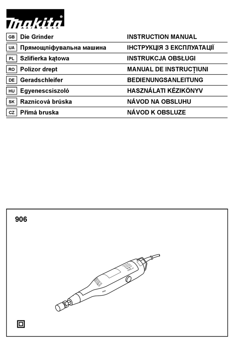
Makita GD0800C User manual

1/4”
MODEL
GDOSOOC
1/4”
MODEL GDOSlOC
CoNet
‘Ize
Model
INSTRUCTION
MANUAL
Max. wheel
No
load speed Overall Net
point diameter
(RPMI
length weight
1
SPECIFICATIONS
GD0800C 371 mm 1.6
kg
114”
25
mm
(1“)
7,000
-
28.000imin.
,14-518,,1
13,5
Ibsl
GO081
OC
1
/4”
50
mm
(2”)
1,800
~
7,00O/min.
1:i:5Eml
El

GENERAL SAFETY RULES
USA0021
(For
All
Tools)
WARNING! Read and understand
all
instructions.
Failure
tofollow all instructions listed below, may result
in
electric
shock,
fire and/or serious personal injury.
SAVE
THESE
INSTRUCTIONS
Work Area
1.
Keep your work area cleanand well
lit.
Clutteredbenches and dark areas invite
accidents.
2.
Donotoperate powertools
in
explosiveatmospheres, such as
in
the presence
of flammable liquids, gases, or dust. Power tools create sparks which may
ignite the dust or fumes.
3.
Keep bystanders, children, and visitors away while operating a power tool.
Distractions can cause you to lose control.
Electrical Safety
4.
DoubleInsulatedtools are equipped
with
a polarized plug (oneblade iswider
than the other.) This plug will
fit
in
a polarized outlet only one way.
If
the
plug does
not
fit
fully
in
the
outlet,
reverse the plug.
If
it
still
does not fit,
contact a qualified electrician to install a polarized outlet. Do not change
the plug
in
any way. Double insulation
El
eliminates the need for the three
wire grounded power cord and grounded power supply system.
5.
Avoid body contact withgrounded surfaces such as pipes, radiators, ranges
and refrigerators. There is an increased risk of electric shock if
your
body
is
grounded.
6.
Donotexpose powertoolstorainor wetconditions. Water entering a power
tool
will
increase the risk of electric shock.
7.
Do
notabuse the cord. Never use the cordtocarry thetoolsor pullthe plug
from anoutlet. Keepcordaway fromheat, oil, sharp edges or movingparts.
Replace damaged cords immediately. Damaged cords increase the risk of
electric shock.
8.
When operating apower tooloutside, usean outdoor extension cord marked
"W-A'
or "W." These cords are rated for outdoor use and reduce the risk
of
electric shock.
Personal Safety
9.
Stay alert, watchwhat youaredoing and usecommon sense whenoperating
a power tool.
Do
not use tool while tired or under the influence of drugs,
alcohol, or medication.
A
moment of inattention while operating powertools
may result
in
serious personal injury.
IO.
Dressproperly.
Do
notwear loose clothing orjewelry. Contain long hair. Keep
your hair, clothing, andglovesawayfrom movingparts. Looseclothes, jewelry
or long hair can be caught
in
moving parts.
2

11.
Avoid accidental starting.
Be
sure
switch
is
off
before
plugging
in.
Carrying
tools withyour finger onthe switchor plugging
in
tools that havetheswitch
on invites accidents.
12.
Remove adjusting keys or wrenches before turning the tool on. A wrench
or a key thatisleftattachedtoa rotatingpartofthetool may result
in
personal
injury.
13.
Do
notoverreach. Keepproper footingand balance atalltimes. Properfooting
and balance enables better control of the tool
in
unexpected situations.
14.
Use safety equipment. Always wear eye protection.
Dust
mask, non-skid
safety shoes, hard hat, or hearing protection must be used for appropriate
conditions.
Tool
Use and Care
15.
Use clamps or other practical way to secure and support the workpiece
to
a stable platform. Holdingthe work by handor against your body is unstable
and may lead to loss of control.
16.
Do
notforce tool. Use the correct toolfor your application. The correct tool
will
do the job better and safer at the rate for which
it
is designed.
17.
Do
not use tool
if
switch does not turn
it
on or off. Any tool that cannot
be controlled
with
the switch is dangerous and must be repaired.
18.
Disconnectthe plugfromthe power source before making any adjustments,
changing accessories, or storing the tool. Such preventive safety measures
reduce the risk of starting the tool accidentally.
19.
Store idle tools out of reach of children and other untrained persons. Tools
are dangerous
in
the hands of untrained users.
20. Maintain tools
with
care. Keep cutting tools sharp and clean. Properly
maintained tools,
with
sharp cutting edges are less likely to
bind
and are easier
to control.
21.
Check for misalignment or binding of moving parts, breakageof parts, and
any other condition that may affect the tools operation.
If
damaged, have
the tool serviced before using. Many accidents are caused by poorly
maintained
tools.
22. Use only accessories that are recommended by the manufacturer for your
model. Accessories that maybe suitablefor one tool, may becomehazardous
when used on another tool.
S
E
RVlC
E
23.
Tool
service must be performed only by qualified repair personnel. Service
or
maintenance performed by unqualified personnel could result
in
a
risk of
injury.
24.
When servicing a tool, use only identical replacement parts. Follow
instructionsinthe Maintenancesectionof this manual. Use of unauthorized
partsor failure
to
follow MaintenanceInstructionsmaycreate a risk
of
electric
shock or injury.
3

Specific Safety Rules
USBOOG
1
1.
Accessories must be rated for at least the speed recommendedon the tool
warning label. Wheels and other accessories running over rated speed can
fly
apart and cause injury.
2.
Holdtool by insulatedgrippingsurfaceswhenperformingan operationwhere
the cutting tool may contact hidden wiring or its own cord. Contact with
a
”live” wire will make exposed metal parts
of
the tool “live“ and shock the
operator.
3.
Use only wheels having a maximum operating speedat least as highas the
highest
No
Load Speed marked on the tool’s nameplate.
4.
Check the wheel carefully for cracks or damage before operation. Replace
cracked or damaged wheel immediately.
5.
Hold the tool firmly.
6.
Keep hands away from rotating parts.
7.
Make sure the wheel is not contacting the workpiece before the switch is
turned on.
8.
Before using the tool on an actual workpiece, let
it
run for a while. Watch
for vibration or wobbling that could indicate poor installation or a poorly
balanced wheel.
9.
Watch out for flying sparks. Holdthe tool
so
that sparksfly away from you
and other persons or flammable materials.
IO.
Do
not leave the tool running. Operate
the
tool only when hand-held.
11.
Do
nottouch the workpiece immediatelyafter operation;
it
may beextremely
hot and could burn your skin.
12.
Always besure you have afirm footing. Be sure noone is below when using
the tool in high locations.
13.
Do
not use water or grinding lubricant.
14.
Do
not use this tool as cutter.
SAVE THESE INSTRUCTIONS.
4

The followings
show
the
symbols
usedfor tool.
v
....................................
volts
A
....................................
amperes
Hz
....................................
herts
%
....................................
alternating current
....................................
noload speed
...................................
Class I1 Construction
..Jmin
...................................
revolutions
or
reciprocation per minute
5

FUNCTIONALDESCRIPTION
Switchaction
CAUTION:
Before plugging in the tool, always check to see that the switch actuates properly and
returnsto the "OFF" positionwhen the sideof the switch lever is depressed.
To start the tool, slide the switch lever
toward the
"I"
position. For continuous
operation, press the front
of
the switch
lever to lock it. To stop the tool, press the
rear of the switchlever, then slide
it
toward
the
"0"
position.
Switch
lever
+I
0
Speed adjustingdial
The tool speed can be infinitely adjusted by turning the speed adjusting dial, which is
marked
1
to
5.
Higher speed
is
obtained
when the
dial
is turned in the direction
of
number
5;
lower speed is obtainedwhen
it
is
turned
in
the directionof number
1.
Refertothe tablebelowfor the relationship
between the number settings on the ad-
justing dialand the approx. tool speed.
GD0800C
GD081
OC
Number
3
-
4
4
-
5
I
17,000
-
24,000
I
4,100
-
5,800
I
24,000
-
28,000
I
5,800
-
7,000
Speed
adjusting
dial
CAUTION:
The speedadjustingdial can be turnedonly as far as
5
and back to
1.
Do
not force it past
5
or
1,
or the speed adjustingfunction may no longer work.
6

ASSEMBLY
Installingor removingwheel point
CAUTION:
Always be sure that the tool is switched
off
and unpluggedbefore installingor removing
the wheel point.
Loosen the collet nut and insert the wheel
point into the collet nut. Use the smaller
wrench to hold the spindle and the larger
one to tighten the collet nut securely.
morethan 8mm
(5/16")
from the collet nut.
Exceeding this distance could cause vibra-
tion or
a
brokenshaft.
To
remove the wheel point, follow the
installationDrocedurein reverse.
The wheel point should not be mounted
I
I
CAUTION:
A
1/4"
collet cone is providedas standard equipment.Use an optionalcollet cone 1/8" to
install
a
1/8" shank wheel point.
8
mm(5/16")
Max
7

Installingthe side handle
Always use the side handleto ensureoper-
atingsafety.
Install the side handle on the tool barrel,
then tighten the handle by turning clock-
wise at the desiredposition.
~
OPERATION
Turn the tool on without the wheel point
makingany contactwith the workpieceand
wait untilthe wheel pointattainsfull speed.
Then apply the wheel point to the work-
piecegently. To obtain
a
good finish, move
the tool inthe leftwarddirection
slowly.
CAUTION:
Apply light pressure on the tool. Excessive pressure on the tool will only cause
a
poor
finish and overloading of the motor.
MAINTENANCE
CAUTION:
Always be sure that the tool is switched off and unpluggedbefore attempting to perform
inspectionor maintenance.
To maintain product SAFETY and RELIABILITY, repairs, carbon brush inspection and re-
placement, any other maintenance or adjustment should be performed by Makita
Authorized or Factory Service Centers, alwaysusingMakitareplacementparts.
8

ACCESSORIES
CAUTION:
These accessories or attachments are recommended for use with your Makita tool specified
in
this
manual. The use
of
any other accessories or attachments might present a risk
of
injury to persons.
The accessories or attachments should be used only inthe proper and intended manner.
Collet cone set
Part~o.
I
Size
192987-1
I
1/8"
192986-3
I
1/4"
Wheel point
0
Q
I-,
<3-.
..._.
.
..
.
.
..
..
:..
..,.
..
19l3/4"l
60
(2-3/8")
Wrench
13
Part No.
781203-2
Wrench
19
Part No.
781206-6
Side
handle
set
Part No.
192985-5
9

10

ITEM NO OESCRlPllON NO USED
I
2
3
4
5
6
7
8
9
IO
It
12
13
14
15
16
I7
18
19
20
21
22
23
24
25
26
28
29
30
31
32
33
34
35
38
,
39
40
41
42
43
44
45
46
41
48
49
50
51
52
53
54
55
56
58
59
COLLET NUT
COLLET CONE
1/4"
SPlNDl F
COLLET NUT
COLLET CONE
1/4"
SPINDLE
OIL
SEAL
16
BEARINGRETAINER
BALL BEARING69OILLB
RETAININGRING 5-12
BARREL
~~
RETAININGRING
S-12
BALL BEARING GOOILLB
RETAINING
RING
R-za
LOCK SPRING 12
COUPLING
PAN HEAD SCREW M4X8
GEAR COVER
(FOR
MODEL GOOBIOC)
0
RING
46
(FOR
MODEL GOO8lOC)
RETAININGRING
A-28
RETAININGRING 5-12
BALL BEARING6001LLB
FLATWASHER
12
BEARINGBOX
FAN51
ARMATUREASS'Y
INC 22.24-26
INSULATIONWASHER
FLAT WASHER
7
BALL BEARING
62100W
LABYRINTH RUBBER RING 22
MAGNETSLEEVE
STOP RING E-4
BAFFLEPLATE
TAPPING SCREW 4x60
RETAINER
INSULATION COVER
FIELD
NAME PLATE
TAPPING SCREW PTJXlO
BRUSH HOLDER
AC CARBON BRUSH CB-318
TAPPING SCREW 4x18
STRAIN RELIEF
SWITCHBLOCK
POWER SUPPLY CORD
CORD GUARD 8
SWITCH
STI
t5A-40
COVER
INDICATION LABEL
REAR COVER
TAPPING SCREW 4x18
CONTROLLER
SWITCHLEVER
COMPRESSIONSPRING
4
BRUSH HOLDER
MOTOR HOUSINGCOMPLETE
CAUTION LABEL
SWITCHKNOB
TAPPING SCREW 4x25
1
1
i
1
t
1
1
1
1
1
\
1
1
1
1
1
1
1
1
1
1
1
1
1
1
1
1
1
1
1
2
2
2
1
1
4
1
1
2
1
1
1
1
1
1
1
1
1
1
1
1
1
1
1
1
4
11

WARNING
Some dust createdby power sanding,sawing, grinding,drilling, and other
constructionactivitiescontainschemicals known[tothe State of California]
to cause cancer, birth defectsor other reproductiveharm.Someexamples
of
these chemicals are:
-
Leadfrom lead-basedpaints,
-
Crystallinesilicafrom bricks andcement andother masonryproducts, and
-
Arsenic andchromiumfrom chemically-treatedlumber.
Your
riskfromthese exposuresvaries, dependingon how often you dothis
type
of
work.
To
reduceyour exposureto thesechemicals:work ina well ventilated
area, and work with approvedsafety equipment,such as thosedust masksthat are
speciallydesignedto filter out microscopicparticles.
____L
QXL
MAKITALIMITED ONE YEAR WARRANTY
Warranty
Policy
Every Makita tool is thoroughly inspected and tested before leaving the factory.
It
is warranted to
be free of dcfects from workmanship and materials for the period
of
ONE YEAR from the date of
original purchase. Should any trouble develop during this one-year period, return the COMPLETE
tool, freight prepaid, toone of Makita's Factory or Authorized Service Centers. If inspection shows
the trouble
is
caused by defectivc workmanship or material, Makita will repair (or at our option.
replace) without charge.
This Warranty does not apply where:
repairs have been made or attempted by others:
repairs are required because of normal wear and tear:
The tool has becn abused, misusod or imvroverlv maintained:
alterationshave been made to the tool.
!
IN
NO EVENT SHALL MAKITA BE LlABLL FOR ANY INDIRECT, INCIDLNTAL OR
CON-
SEQUENTIAL DAMAGES FROM THE SALE OR US6 OF THE PRODUCT THIS DISCLAIM[ R
APPLIES BOTH DURING AND ArTER THETERM OFTHISWARRANTY
1
MAKITA DISCLAIMS LIABILITY FOR ANY IMPLIED WARRANTIES, INCLUDING IMPLIED
WARRANTIES
OF
"MERCHANTABILITY" AND "FITNESS FOR A SP1.CIFIC PURPOSI.,"
AFTER THE ONE-YEAR TERM OFTHIS WARRANTY.
I
This Warranty gives you specific legal rights, and you may also have other rights which vary from
state to state. Some statcs do not allow the exclusion
or
limitation of incidcntal or consequential
damages,
so
the above limitation
or
exclusion may not apply to
you.
Some states do not
alluw
limitation on how
long
an implied warranty lasts,
so
the above limitation may not apply to you.
---e*-
Makita Corporation
3-11
-8, Sumiyoshi-cho,
Anjo, Aichi 446-8502 Japan
884314-065
PRINTED
IN
JAPAN
2000-9-N
Other manuals for GD0800C
21
This manual suits for next models
1
Table of contents
Other Makita Grinder manuals

Makita
Makita GAG06Z User manual

Makita
Makita GA4540R User manual

Makita
Makita DGA521 User manual

Makita
Makita GA037G User manual

Makita
Makita 9557HP User manual

Makita
Makita DGA411 User manual

Makita
Makita GA9063 User manual

Makita
Makita GA7012C User manual

Makita
Makita GA011G User manual

Makita
Makita GA038GZ User manual

Makita
Makita 9561CVH User manual

Makita
Makita DGA417RTE User manual

Makita
Makita 9560Z User manual

Makita
Makita GD0603 User manual

Makita
Makita GA043G User manual

Makita
Makita 9556PB User manual

Makita
Makita 9562 Manual

Makita
Makita 9558HNR User manual

Makita
Makita DGA700 User manual

Makita
Makita DGA404 User manual