Makita GSE2200 User manual

for authorized workshops
GSE2200

2
1. USING THIS MANUAL
The instructions provided in this manual are intended for and delivered solely to
authorized workshops recognized by the manufacturer, and are intended to complete the
Instruction and Maintenance manual supplied with each garden shredder.
All specialized personnel must therefore carefully read the aforementioned Instruction and
Maintenance Manual as well, before performing any type of diagnostics or intervention on
the shredder.
The purpose of this manual is to provide all necessary information to skillfully and safely
perform special maintenance on the product.
Manual Contents
1. Using this Manual
2. Special maintenance
3. Technical service
4. Warranty
5. Sharpening the blades
Replacing the vertical blades
6. Replacing the spring that immediately stops the blades
7. Safety rules for the mechanical maintenance technician
8. Safety rules for the electrical maintenance technician
9 Electrical schematics

3
GARDEN SHREDDERS
Fig. 1

4
2. SPECIAL MAINTENANCE
Special maintenance must be carried out by trained personnel
This includes:
- working on worn, defective or broken parts;
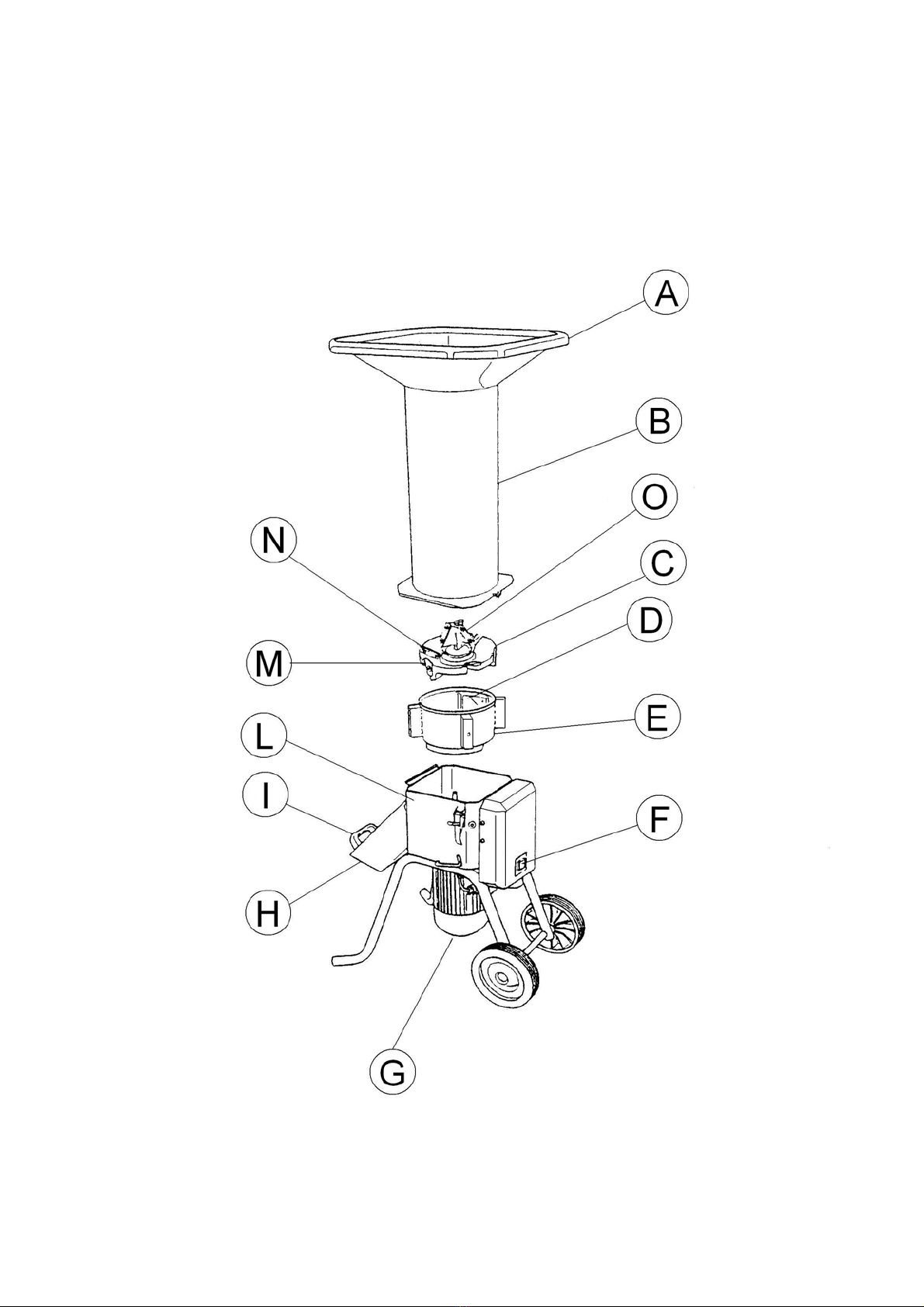
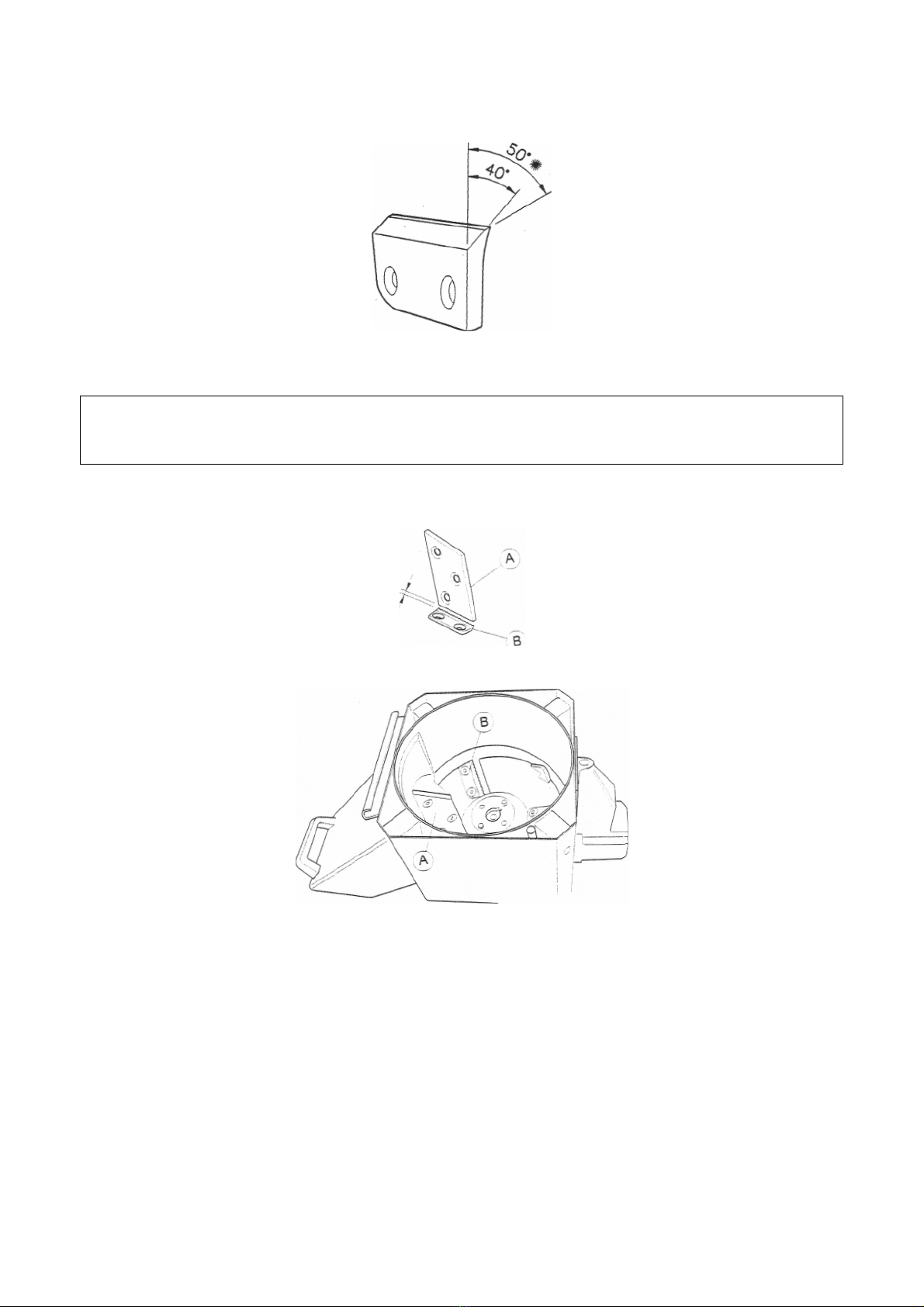
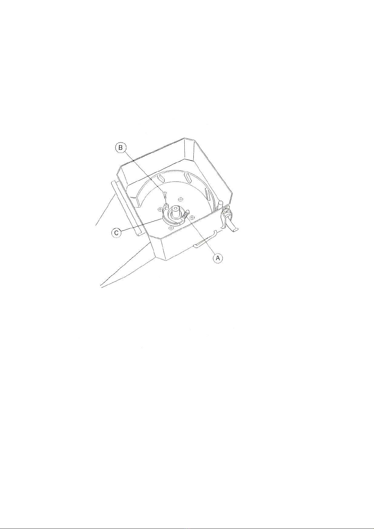
- replacement of the vertical blades (fig. 1 point M), since they are located in a position
that requires complete disassembly of the cutting unit and subsequent adjustments for
repositioning;
- sharpening the blades (the blades wear down naturally as they work: tough material
will cause them to wear more rapidly than soft material; when the blades have lost their
edge and the material is no longer shredded as finely as before, they must be
sharpened);
- work on the electrical system (all intervention on the electrical system must be carried
out by a specialized electrical maintenance technician).
3. TECHNICAL SERVICE
Special maintenance must be carried out in compliance with the instructions contained in
this manual. For all cases not included, we urge you to contact the manufacturer directly,
referring to the data listed on the identification plate attached to the machine.
Providing correct references ensures a rapid, accurate response.
For prompt delivery of spare parts, the following information must always be included in
the order:
- Machine model and serial number
- Description of the component and quantity desired
4. WARRANTY
The shredder is guaranteed for 12 months from the purchase date, not including electrical
parts.
The manufacturer will replace any parts found to be defective at no charge. Labor and
shipping costs shall be at the purchaser's expense.
The manufacturer must be notified immediately of any damage attributed to shipping.
Concerning materials not manufactured by us, particularly the motor, you must follow the
rules set forth by the respective manufacturers. Therefore, any repair requests must be
forwarded to the specific service center in the appropriate area.
If machine maintenance has not been carried out according to the instructions provided,
using non-original spare parts or without written authorization by the manufacturer, or in
any case in such a way as to interfere with the integrity of the machine or alter its charac-
teristics, the manufacturer shall be relieved of any liability regarding personal safety and
defective operation of the machine.
Any unauthorized alterations shall void the contractual warranty.

5
5. SHARPENING THE BLADES
At least one complete set must be sharpened to avoid problems with imbalance,
especially notable when rotation is fast.
Each set of blades is made up of:
- qty. 3 horizontal blades positioned on the cutting disk (Fig. 1, point N)
or
- qty. 3 vertical blades positioned on the outer edge of the cutting disk (Fig.1, point M).
or
- qty. 3 slanted blades positioned on the upper rotor (Fig.1, point O).
The horizontal and the slanted blades will be delivered as separate parts, removed from
the machine directly by the user.
The vertical blades must be disassembled by trained personnel, who will replace and
adjust them after sharpening.
To remove the vertical blades from the cutting disk, we recommend that you follow
the instructions below:
- disconnect the machine from the electrical mains;
- set the knob (Fig. 2, point A) to position 2
- release the feeder pipe from the shredder body using the two hooks provided (Fig. 2
point B), and disassemble;
- unscrew and remove the four screws (visible from outside the shredder body) holding
the support pipe of the counter-blade (Fig.3, point C) ;
- remove the counter-blade support pipe (Fig.1, point E);
- unscrew the central screw holding the rotor (Fig. 3 point A)
- remove the cutting disk (Fig. 1 point C). If it is stuck in position, you must use an
extractor, using leverage against the two holes on either side of the central disk hole;
- unscrew the holding screws of the vertical blades, then remove the blades.

6
Fig. 2

7
Fig. 3
After sharpening (at approximately 40° as shown in the figure below) or changing the
blades, they must be re-assembled in reverse order. We recommend fastening the blade
screws in place with LOCTITE.

8
Figure for sharpening ( Fig. 4 )
Sharpening angle
WARNING
When re-positioning the counter-blade support pipe, make especially sure that there is a
space of no less than 2 mm between the counter-blade and the blade (Figure 5).
Fig.5
After completing assembly, make sure that the feeder pipe rests firmly against the
shredder body and is properly connected via the knob shown in Fig. 2 point A (position 1
to lock) and the side hooks (Fig. 2 point B); then check the rotation to see whether the
machine is working smoothly. When the blades are worn due to harsh working conditions
or repeated sharpening, you must install new blades.

9
6. REPLACING THE SPRING THAT IMMEDIATELY STOPS THE BLADES
If a fault occurs on the spring, thereby interfering with the immediate stop of the blade disk
when the feeder pipe is opened, it is necessary to replace the spring itself (Fig. 6 Point A)
To replace the spring, we recommend that you follow the instructions below:
- disconnect the machine from the electrical mains;
- set the knob (Fig. 2, point A) to position 2
- release the feeder pipe from the shredder body using the two hooks provided (Fig. 2
point B), and disassemble;
- unscrew and remove the four screws (visible from outside the shredder body) holding
the support pipe of the counter-blade (Fig.3, point C) ;
- remove the counter-blade support pipe (Fig.1, point E);
- unscrew the central screw holding the rotor (Fig. 3 point A)
- remove the cutting disk (Fig. 1 point C). If it is stuck in position, you must use an
extractor, using leverage against the two holes on either side of the central disk hole;
- unscrew the screw holding the brake block (Fig. 6 point B)
- Remove the brake block (Fig.6, point C) and replace the existing spring with a new one
in perfect condition, supplied by the shredder manufacturer.
Then re-assemble the various parts by following the same procedure in reverse order.
WARNING
When re-positioning the counter-blade support pipe, make especially sure that there is a
space of no less than 2 mm between the counter-blade and the blade (Figure 5).
After completing assembly, make sure that the feeder pipe rests firmly against the
shredder body and is properly connected via the knob shown in Fig. 2 point A (position 1
to lock) and the side hooks (Fig. 2 point B); then check the rotation to see whether the
machine runs correctly, and check the efficiency of the safety device, thus that the blade
disk stops immediately when the feeder pipe is opened, following the instructions provided
in Chap. 9 of the Instruction and Maintenance manual (section «Check the efficiency of
the safety device»).

10
FIG.6

11
7. SAFETY RULES FOR THE MECHANICAL MAINTENANCE TECHNICIAN
• After each maintenance intervention or adjustment, make sure that you have left no
tools or foreign objects among the moving parts of the machine, to avoid damaging the
machine and/or injuring personnel.
• Always keep the area used for maintenance operations clean and dry, being especially
careful to remove any oil slicks.
• Never insert your body, limbs or fingers into jointed or sharp openings in machine parts
without protection.
• Do not align holes or slots by hand: use only appropriate tools.
• Do not use petrol or flammable solvents as cleansers; always use authorized
commercial solvents that are not flammable and non-toxic.
• Do not use compressed air to clean parts; if it is impossible to use other means,
protect yourself using goggles with side guards, and limit the pressure to a maximum
of 2 bar.
• Never use an open flame for lighting when checking or servicing the machine.
8. SAFETY RULES FOR THE ELECTRICAL MAINTENANCE TECHNICIAN
• Before any intervention on the electrical components, make sure the power line has
been disconnected.
WARNING
Danger of electrocution
In case of electrical accident, promptly remove the victim (usually unconscious) from all
live parts. Cut off power to the electrical line. If this would take too long, move the accident
victim using an insulating material such as a rod made of wood, PVC, fabric, leather.
Promptly call medical personnel to take the patient to the hospital.
This operation is very dangerous: touching the victim will electrocute you as well.

12
Electrical schematics

13

14

15

16

17

18
Table of contents
Other Makita Paper Shredder manuals
Popular Paper Shredder manuals by other brands

UNITED OFFICE
UNITED OFFICE KH 4407 SHREDDER operating instructions

Primera
Primera DS360 Operator's manual

texet
texet CD1412 instruction manual

Talex
Talex LEOPARD 320/O PROFESSIONAL Instruction Manual-Catalogue of Parts-Warranty

HSM
HSM SECURIO Auto Feed 150C operating instructions

Hyundai power products
Hyundai power products HBT420 Original instructions