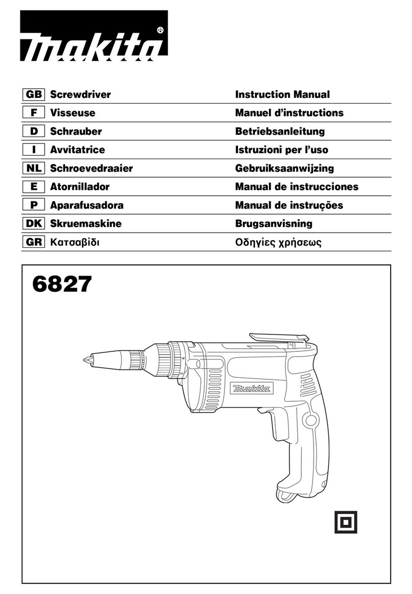
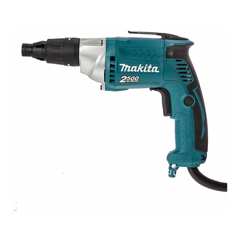
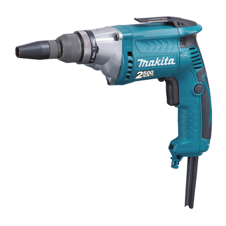
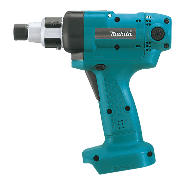
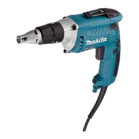
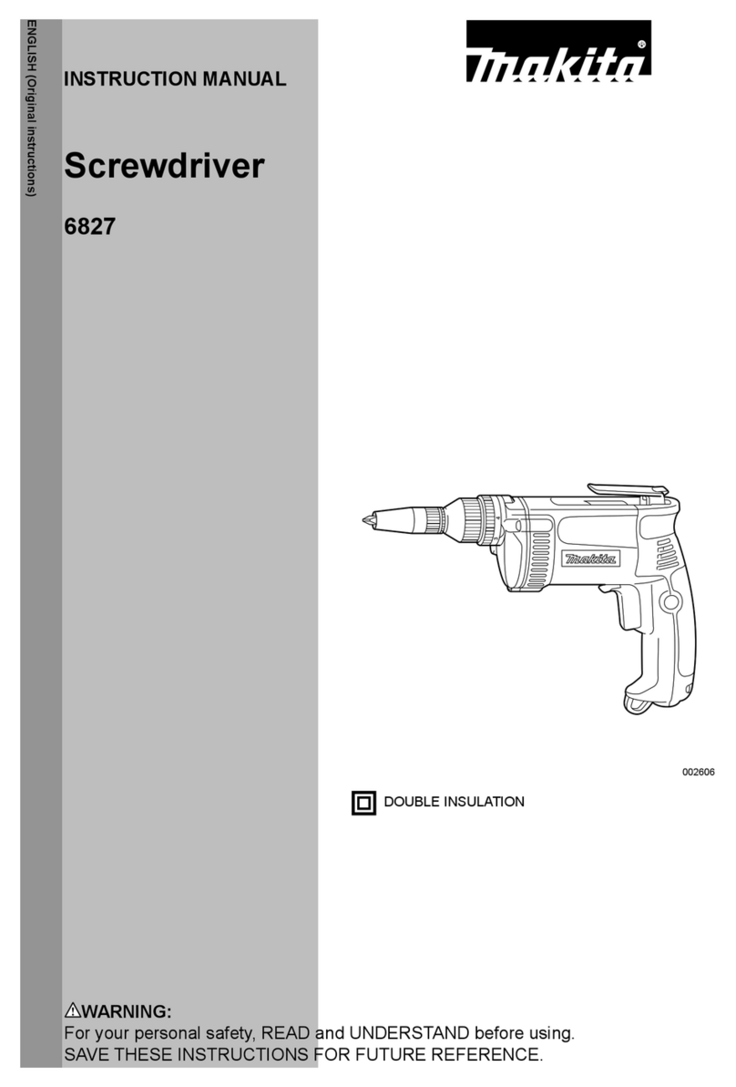
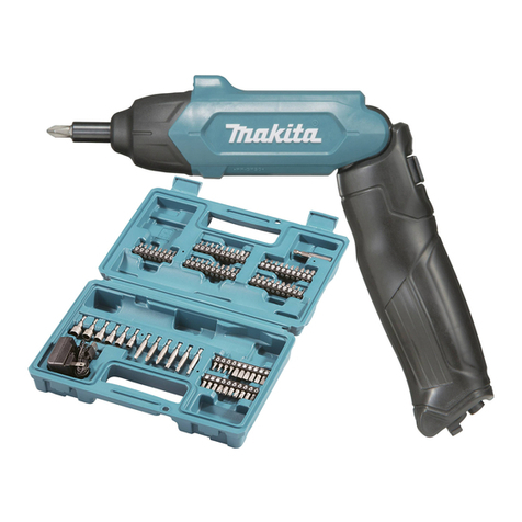
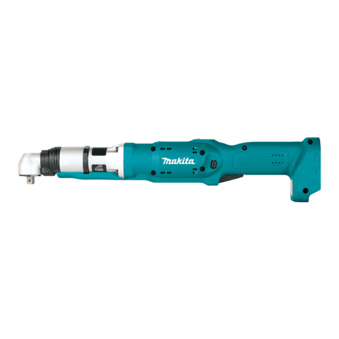
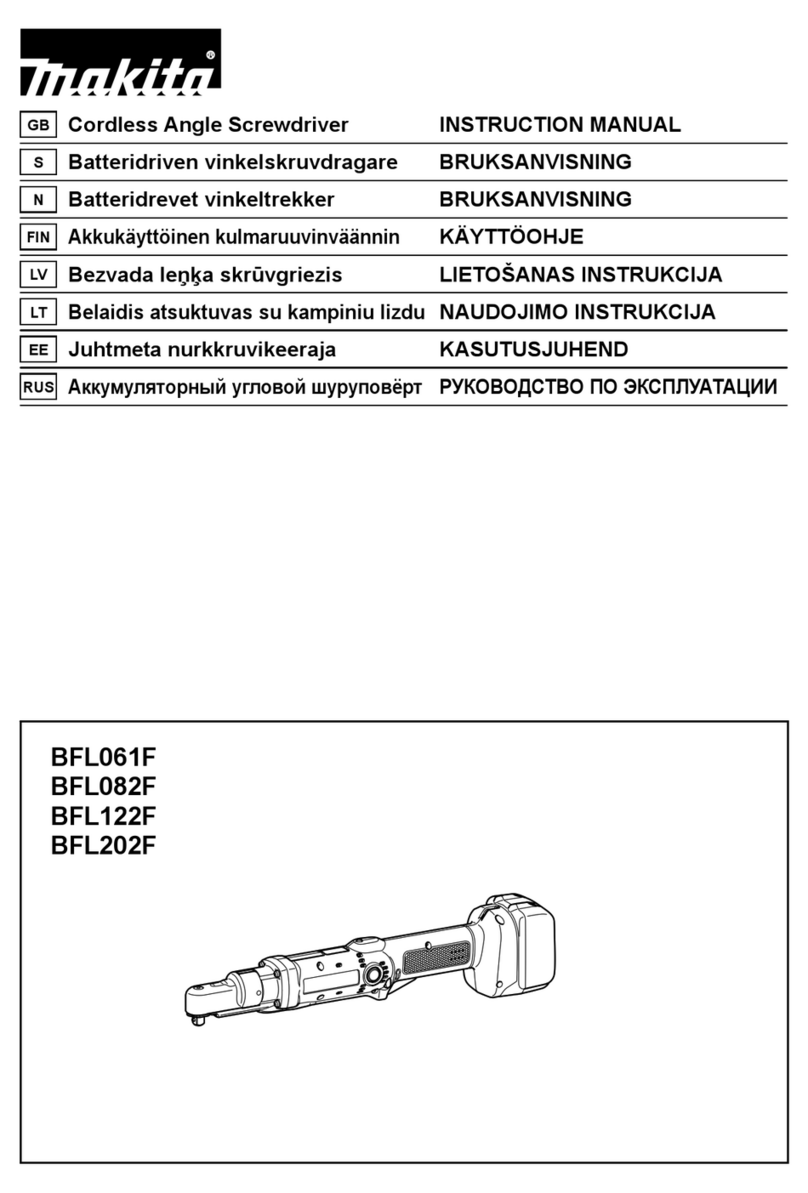
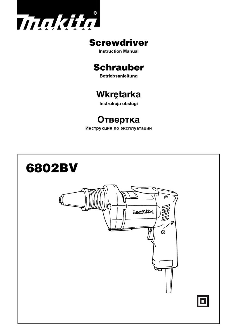
Makita 6827 User manual

Screwdriver
Self
drilling
screw
MODEL
6827
Variable
Speed
/
Reversing
Machine screw
Wood
screw
INSTRUCTION
MANUAL
DOUBLE
INSULATION
SPECIFICATIONS
6
mm
(114”)
I
8
mm
15/16”)
16.2
mm
(114”)
10
~
2,500imin.
I304
mm
(12”)
1
1.8
kg
14.0
Ibs)
*
Manufacturer reserves the right
to
change specifications without notice.
*
Note: Specifications may differ from country
to
country.
WARNING: For your personal safety, READ and UNDERSTAND before using.
SAVE THESE INSTRUCTIONS FOR FUTURE REFERENCE.

GENERAL SAFETY RULES
USA0021
(For
All
Tools)
WARNING! Read and understand all instructions.
Failure
to follow
all
instructions listed below, may result
in
electric
shock, fire and/or serious personal injury.
SAVE
THESE
INSTRUCTIONS
Work Area
1.
Keep your work areacleanand well
lit.
Clutteredbenches and dark areas invite
accidents.
2.
Do
notoperate powertools
in
explosiveatmospheres, such as
in
the presence
of flammable liquids, gases, or dust. Power tools create sparks which may
ignite the dust or fumes.
3.
Keep bystanders, children, and visitors away while operatinga power tool.
Distractions can cause
you
to lose control.
Electrical Safety
4.
DoubleInsulatedtools areequipped witha polarized plug(oneblade iswider
than the other.) This
plug
will
fit
in
a polarized outlet only one way. Ifthe
plug does not fit fully
in
the outlet, reverse the plug.
If
it
still does not fit,
contact a qualified electrician to install a polarized outlet.
Do
not change
the plug
in
any way. Double insulation
El
eliminates the need for the three
wire grounded power cord and grounded power supply system.
5.
Avoid body contact withgrounded surfaces such as pipes, radiators, ranges
and refrigerators. There is an increased risk of electric shock if your body is
grounded.
6.
Donotexpose powertools torainor wet conditions. Water enteringa power
tool
will
increase the risk of electric shock.
7.
Do
notabuse the cord. Never use the cordtocarry the
tools
or
pullthe plug
from
an
outlet. Keepcordaway fromheat, oil, sharp edges or movingparts.
Replace damaged cords immediately. Damaged cords increase the risk of
electric shock.
8.
When operating a powertooloutside, use an outdoorextension cordmarked
"W-A' or "W." These cords are rated for outdoor use and reduce the risk
of electric shock.
Personal Safety
9.
Stay alert, watchwhat youaredoing and usecommon sensewhenoperating
a power tool. Do not use tool while tired or under the influence of drugs,
alcohol, or medication.
A
moment of inattentionwhile operating power tools
may result
in
serious personal injury.
IO.
Dressproperly. Donotwear loose clothing orjewelry. Contain longhair. Keep
your hair, clothing, andglovesaway from movingparts. Looseclothes,jewelry
or long hair can be caught
in
moving parts.
2

11.
Avoid accidental starting. Be sure switch
is
off
before plugging
in.
Carrying
tools
with
your finger onthe switchor plugging
in
tools that have theswitch
on invites accidents.
12.
Remove adjusting keys or wrenches before turning the tool on. A wrench
or a key that is left attachedtoa rotating partof thetool may result
in
personal
injury.
13.
Donotoverreach. Keepproper footingandbalance at
all
times. Properfooting
and balance enables better control of the tool
in
unexpected situations.
14.
Use safety equipment. Always wear eye protection. Dust mask, non-skid
safety shoes, hard hat,
or
hearing protection must be used
for
appropriate
conditions.
Tool
Use and Care
15. Use clamps or other practical way to secure and support the workpiece to
a stableplatform. Holdingthe work by handor against your body is unstable
and may lead to
loss
of control.
16.
Do
notforce tool. Usethe correct tool for your application. The correct tool
will
do the job better and safer at the rate for which
it
is designed.
17. Do not use tool if switch does not turn
it
on or off. Any tool that cannot
be controlled
with
the switch is dangerous and must be repaired.
18.
Disconnectthe plugfromthepower source before makingany adjustments,
changing accessories,
or
storing the tool. Such preventive safety measures
reduce the risk of starting the tool accidentally.
19.
Store idle
tools
out of reach of children and other untrained persons.
Tools
are dangerous
in
the hands of untrained users.
20.
Maintain tools
with
care. Keep cutting tools sharp and clean. Properly
maintained tools, with sharp cutting edges are less likely tobindand are easier
to control.
21.
Check for misalignment or binding of moving parts, breakage of parts, and
any other condition that may affect the tools operation. If damaged, have
the tool serviced before using. Many accidents are caused by poorly
maintained tools.
22. Use only accessories that are recommended by the manufacturer for your
model. Accessories that may be suitablefor one tool, may becomehazardous
when used on another tool.
S
ERVl
C
E
23.
Tool
service must be performed only by qualified repair personnel. Service
or maintenance performed by unqualified personnel could result in a risk of
injury.
24.
When servicing a tool, use
only
identical replacement parts. Follow
instructions
in
the Maintenancesectionof this manual. Use of unauthorized
parts or failure
to
follow MaintenanceInstructionsmaycreate a riskof electric
shock or injury.
3
US8004
1
Specific Safety Rules
1.
Holdtool by insulated grippingsurfaceswhen performing an operation where
the cutting tool may contact hidden wiring or its own cord. Contact with a
"live" wire will make exposed metal parts
of
the
tool
"live" and shock the
operator.
Be sure no one is below when using the tool in high locations.
2.
Always be sure you have
a
firm footing.
3.
Hold the tool firmly.
4.
Keep hands away from rotating parts.
5.
Do
nottouch the bit or the workpiece immediately after operation: they may
be extremely hot and could burn your skin.
SAVE THESE INSTRUCTIONS.
SYMBOLS
The followings showthe symbols usedfor tool.
v
....................................
volts
A
....................................
amperes
Hz
....................................
herts
TJ
....................................
alternating current
b
....................................
no load speed
u
....................................
Class
ti
Construction
.../
min
...................................
revolutionsor reciprocationper minute
4

FUNCTIONAL
DESCRIPTION
Switch action
CAUTION:
Beforepluggingin the tool, always check to see that the switch trigger actuates properly
and returnsto the
"OFF"
positionwhen released
To start the tool, simply
pull
the trigger.
Tool
speed is increased by increasing pres-
sure on the trigger. Release the trigger to
stop. For continuous operation, pull the
trigger and then push in the lock button.
To
stop the tool from the locked position,
pullthe trigger fully, then release
it.
Lock
button
Switch trigger
\
NOTE:
Even with the switch on and motor running, the bit will not rotate until
you
fit the point of
the bit inthe screw headand apply forward pressureto engage the clutch.
Reversing switch action
CAUTION:
*Always check the direction
of
rotationbeforeoperation.
*Use the reversingswitch only after the tool comes to
a
complete stop. Changing the
directionof rotationbeforethe tool stops may damage the tool.
-i
This tool has a reversingswitch to change
the direction
of
rotation. Move the revers-
ing switch lever to the
A
side for clockwise
rotationor the
B
side for counterclockwise
rotation.
Reversing witch lever
I
5

Hook
The hook
is
convenientfor temporaw hangingthe tool. When using the hook, pull it out in
"A"
directionand then push it in
B
directionto securein place.
When not using the hook, return
it
back to its initialposition
by
followingthe above proce-
dures in reverse.
Depth adjustment
Whenyou wish to drive self drillingscrews,
etc., adjust the depth
as
follows. Turn the
locator to adjust the depth.
Initially, adjust the locator to create
a
distance
of
approximately
1
mm
(3/64")
from the tip
of the front cap (whichworks in conjunction with the locator) to the base
of
the screw
head. Onefull turn of the locator equals
1
mm
(3/64")
change indepth. After adjustingthe
locator, turn the adjusting ring
so
that the
6"
mark is aligned with the pointer on the gear
housing. Drive
a
trial screw into your material or
a
piece
of
duplicate material. If the depth
is not suitable for the screw, continueadjusting untilthe proper depthsetting is obtained.
6

Adjusting fasteningtorque
When you wish to drive machine screws,
wood screws, hex bolts etc. with the pre-
determined torque, adjust the fastening
torque as follows.
The fastening torque may be adjusted by
turning the adjusting ring. Before turning
the adjusting ring, turn the locator in the
direction of the arrow as far as it will go
without forcing. The torque
is
increased by
turning the adjusting ring in the directionof
the arrow anddecreased by turning
it
inthe
opposite direction. Align the number
1
on
the adjusting ring with the pointer on the
Adjusting
ring
7
7
Locator
2
Pointer
1
gear housing. Drive a trial screw into your material or a piece of duplicate material. If the
fastening torque is not suitable for the screw, continue adjusting untilthe proper torque is
obtained.
CAUTION:
The adjusting ring should be turned only within the numbered range.
It
should not be
forced beyondthis range.
ASSEMBLY
Removing or installingbit
CAUTION:
Always be sure that the tool
is
switched off and unplugged before removing or installing
the bit.
To
removethe bit, first pull the front capoff
andthen
pull
the bitfirmly. To installthe bit,
insert it into the tool as far as it will go and
then replacethe front cap.
7

OPERATION
Fit the screw on the point of the bit and
placethe point of the screw on the surface
of the workpiece to be fastened. Apply
pressureto the tool and start it. Withdraw
the tool as soon as the clutchcuts in. Then
releasethe trigger.
CAUTION:
*When fittingthe screw ontothe point
of
the bit, becareful notto push inon the screw.
If
the screw is pushedin, the clutch will engage and the screw will rotate suddenly.This
coulddamage
a
workpieceor cause an injury.
*Make sure thatthe bit is insertedstraight inthe screw head, or the screw andlor bit may
be damaged.
NOTE:
*Make sure that the driver bit is insertedstraight inthe screw head, or the screw andlor
bit my be damaged.
*When driving wood screws, predrill pilot
holes to make driving easier and to pre-
vent splitting of the workpiece. See the
chart.
Nominaldiameter Recommended
size
of
wood screw
of
pilot
hole
5/64"
9/64" 3/32"
5/32"
I
7/64"
11/64"
I
1"'
3116"
I
1"'
13/64"
I
9/64"
7/32"
I
5/32"
15/64"
I
11/64''
1/4
"
I
11/64''
MAINTENANCE
CAUTION:
Always be sure that the tool is switchedoff and unplugged beforeattemptingto perform
inspectionor maintenance.
To
maintain product SAFETY and RELIABILITY, repairs, carbon brush inspection and
replacement, any other maintenance or adjustment should be performed by Makita
Authorized or FactoryService Centers, alwaysusingMakitareplacementparts.
8

ACCESSORIES
Part
No.
322124-5
322125-3
322119-8
322126-1
322120-3
CAUTION:
These accessories or attachments are recommended
for
use
with
your
Makita
tool
specified
in
this
manual. The use
of
any other accessories or attachments might present a risk
of
injury to persons.
The accessories or attachments should be used
only
in the proper and intendedmanner.
Size
114
"
5116"
3/8"
7/16"
Magneticsocket bit Front cap
784804-5
Part
No.
I
Size
511
6"
784803-7
I
I
I4
"
784805-3
I
7116"
Phillipsbit
rn-8
Slotted bit
784214-OA 78401
0-OA
78421
5-0A
784011-OA
Square drill bit
Part
No.
784606-0A
Steelcarrying case
Part No. 183158-1
9

10

ITEM NO DESCRIPTION NO USED ITEM NO DESCRIPTION
1
2
3
4
5
6
7
8
9
10
II
12
15
16
17
20
21
22
23
24
25
26
27
28
29
30
31
32
33
FRONT CAP
10
1
0
RING 20
I
ADJUST SLEEVE
1
RING SPRING 22
1
CLUTCH COVER
1
0
RING 35
1
FLAT WASHER 36
I
RING 36 COMPLETE
1
STEEL BALL4
1
COMPRESSION SPRlNG 4
1
TAPPING SCREW
4x30
3
GEAR HOUSING
1
BALL BEARING
606
I
GEAR COMPLETE 17-35
I
FLAT WASHER 8
1
THRUST NEEDLE BEARING 821
1
URETHANE WASHER
8
1
GEAR HOUSING COVER COMPLETE
1
BALL BEARING 608VV
1
ARMATURE ASS'Y
1
INC 23.25.26.44.48
INSULATION WASHER
1
BALL BEARING 607LLB
1
RUBBER RING 19
1
BAFFLE PLATE
1
TAPPING SCREW 4x55 2
FIELD
1
HOOK
1
MOTOR HOUSING SET
1
INC 33
MAKITA L.ABEL
I
34
35
36
37
38
39
40
41
42
43
44
45
46
47
48
49
50
51
52
53
54
55
56
57
58
59
BO
61
62
63
64
65
NAME PLATE
BRUSH HOLDER
CARBON BRUSH '26-407
POWER SUPPLY CORD
CORD GUARD
8
STRAIN RELIEF
TAPPING SCREW 4x18
SWITCH CJMA-L
HANDLE COVER COMPLETE
TAPPING SCREW 4x25
FLAT WASHER
E
BRUSH HOLDER
RING 8
TAPPING SCREW 4x25
FAN 52
RING 20
LEAF SPRING
STEEL BALL 3 5
SPINDLE ASS'Y
INC
50.51
COMPRESSION SPRING
6
CLUTCH CAM
PIN 4
PIN4
COMPRESSION SPRING 13
6
FLAT WASHER 14
STEEL BALL3 2
SLEEVE
THRUST NEEDLE BEARING 1831
STEEL BALL
5
6
GEAR COMPLETE
GASKET
PIN
3
NO USED
1
1
1
1
1
1
2
1
1
1
1
1
1
2
1
1
1
1
1
1
1
1
1
1
1
16
1
1
3
1
1
1
11

1
WARNING
Some dust created by power sanding, sawing, grinding, drilling, and other
construction activities contains chemicals known
[to
the State of California]
to
cause cancer, birth defects or other reproductive harm. Some examples
of
these chemicalsare:
0
Leadfrom lead-based paints,
0
Crystalline silica from bricksand cement and other masonry products, and
e
Arsenic and chromiumfrom chemically-treated lumber.
Your risk from these exposures varies, depending on how often you do this
type
of
work.
To
reduce your exposure
to
these chemicals:
work
in a well
ventilated area, and work with approved safety equipment, such as those
dust masksthat are specially designed
to
filter out microscopicparticles.
MAKITA
LIMITED
ONE YEAR WARRANTY
Warranty Policy
Every Makita
tool
is thoroughly inspected and tested before leaving the factory.
It
is warranted
to
be free of defects from workmanship and materials for the period of
ONE YEAR
from the date
of
original purchase. Should any trouble develop during this one-year period, return the
COMPLETE
tool, freight prepaid,
to
one of Makita’s Factory or Authorized Service Centers.
If
inspection shows
the trouble is caused by defective workmanship
or
material, Makita will repair (or at our option,
replace) without charge.
This Warranty does not apply where:
repairs have been made or attempted by others:
repairs are required because of normal wear and tear
The tool has been abused, misused or improperly maintained;
alterationshave been made to the tool.
IN NO EVENT SHALL MAKITA BE LIABLE
FOR
ANY INDIRECT, INCIDENTAL OR CON-
SEQUENTIAL DAMAGES FROM THE SALE
OR
USE
OF
THEPRODUCT. THIS DISCLAIMER
APPLIES BOTH DURING AND AFTER THETERM
OF
THISWARRANTY.
MAKITA DISCLAIMS LIABILITY FOR ANY IMPLIED WARRANTIES, INCLUDING IMPLIED
WARRANTIES OF “MERCHANTABILITY” AND “FITNESS FOR A SPECIFIC PURPOSE.
AFTER THEONE-YEAR TERM OFTHIS WARRANTY.
This
Warranty gives you specific legal rights, and you may also have other rights which vary from
state
to
state. Some states do not allow the exclusion or limitation
of
incidental or consequential
damages,
so
the above limitat/on or exclusion may not apply to you. Some states do not allow
limitation onhow long an implled warranty lasts,
so
the above limitation may not apply loyou.
Makita Corporation
3-11
-8,
Sumiyoshi-cho,
Anjo, Aichi 446-8502 Japan
PRINTED
IN
JAPAN
2000
-
12
-
N
Other manuals for 6827
6
Table of contents
Other Makita Power Screwdriver manuals

Makita
Makita 6833 User manual

Makita
Makita 6805BV User manual

Makita
Makita 6822 User manual

Makita
Makita DA330D User manual

Makita
Makita BFL060F User manual

Makita
Makita DDA341 User manual

Makita
Makita 6826 User manual

Makita
Makita DFS451RMJ User manual

Makita
Makita BFS440 User manual

Makita
Makita DFS441 User manual

Makita
Makita DFL083F User manual

Makita
Makita DFT022F User manual

Makita
Makita DFT024F User manual

Makita
Makita 6835D User manual

Makita
Makita DFS441 User manual

Makita
Makita FS2700 User manual

Makita
Makita FS2200 User manual

Makita
Makita DFS250 User manual

Makita
Makita DDA340 User manual

Makita
Makita FS2200 User manual