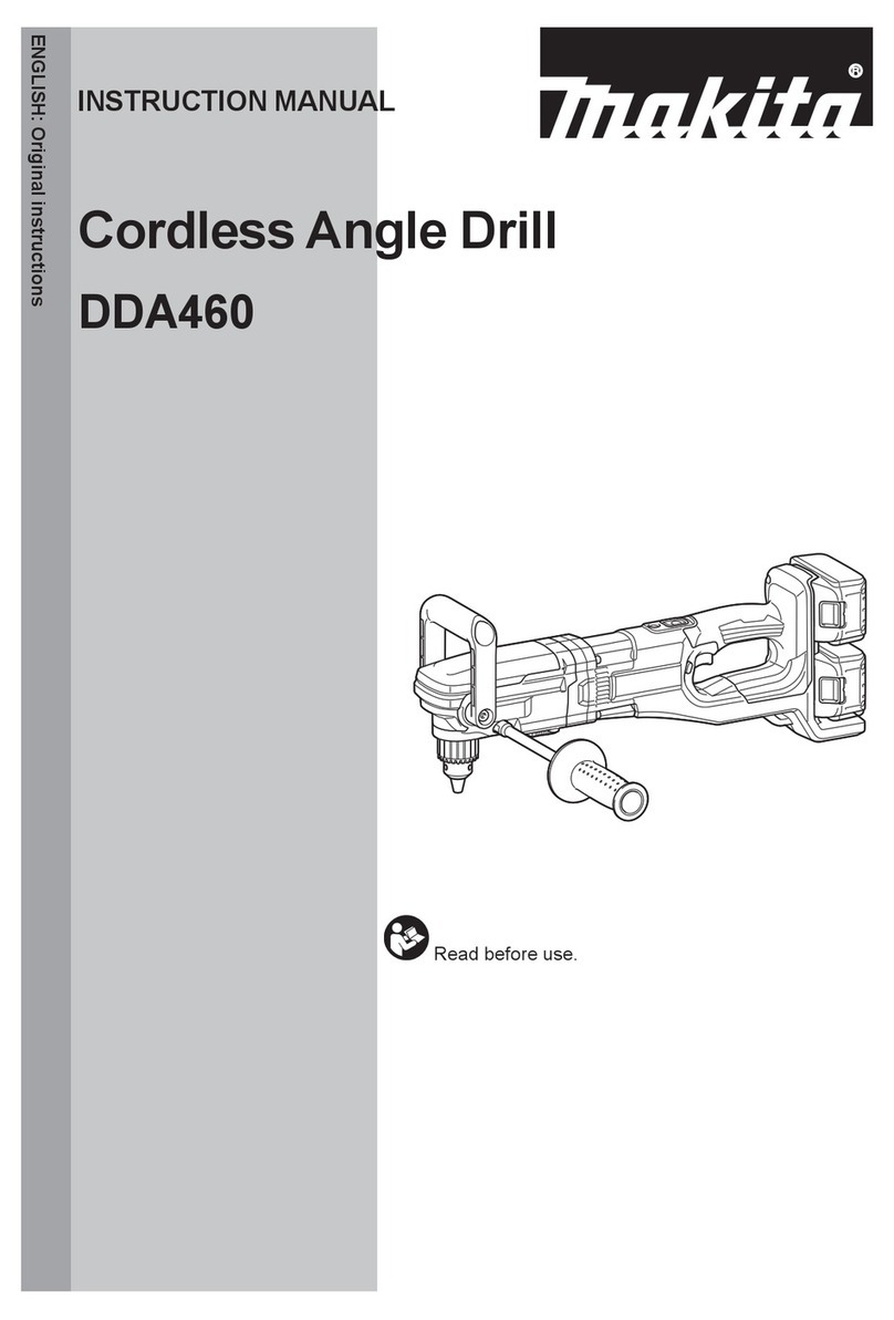
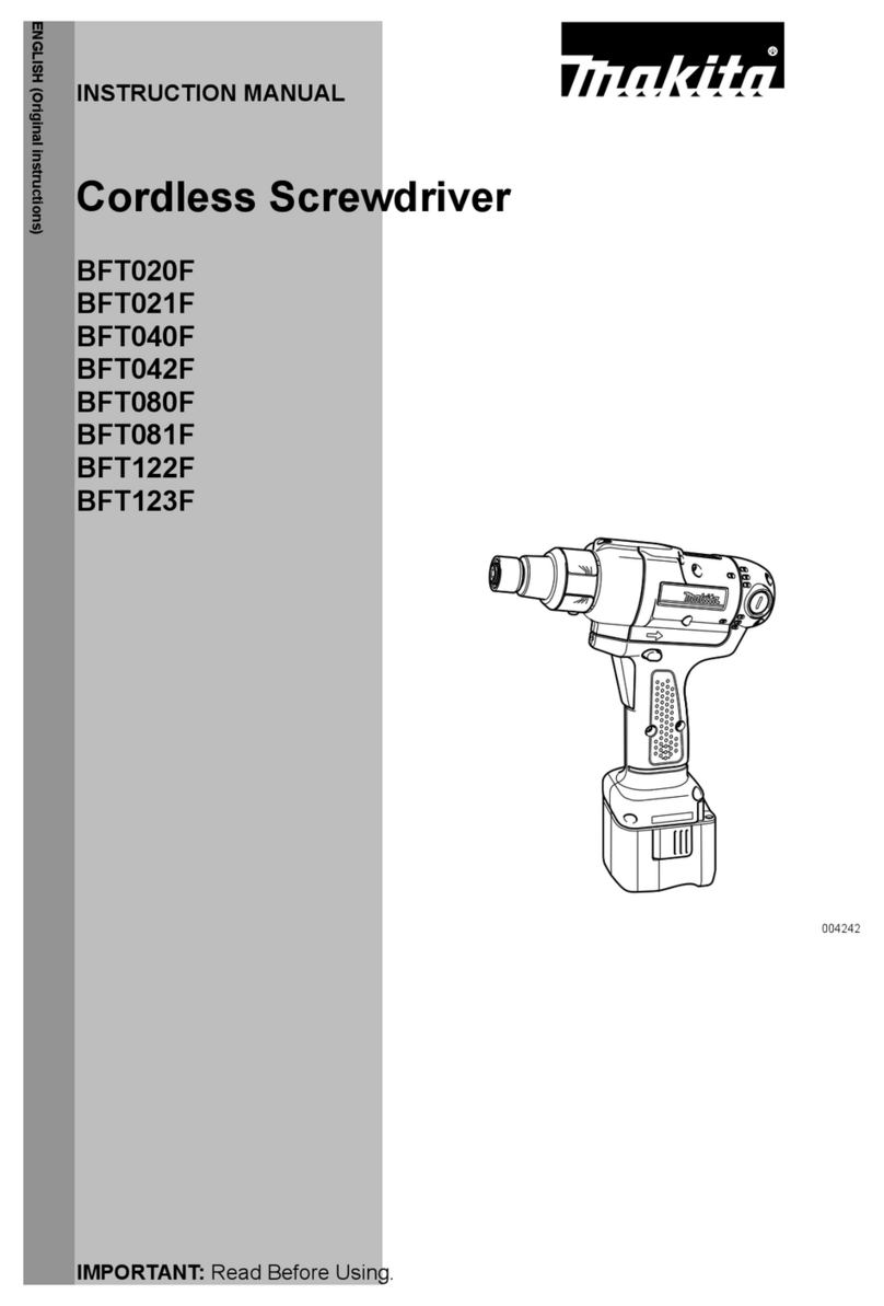
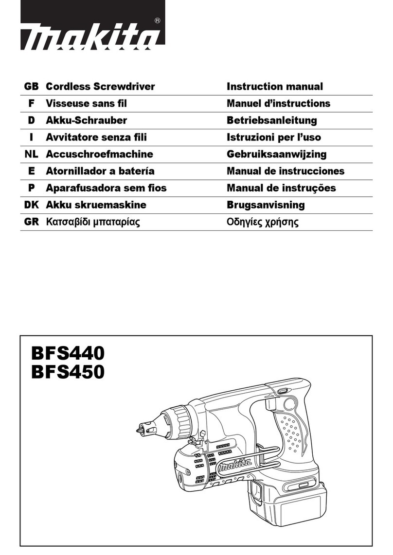
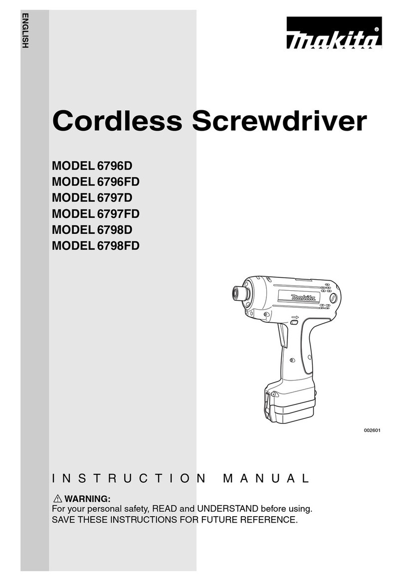
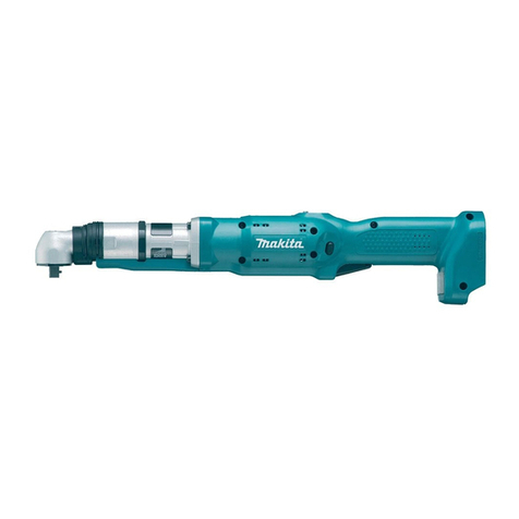
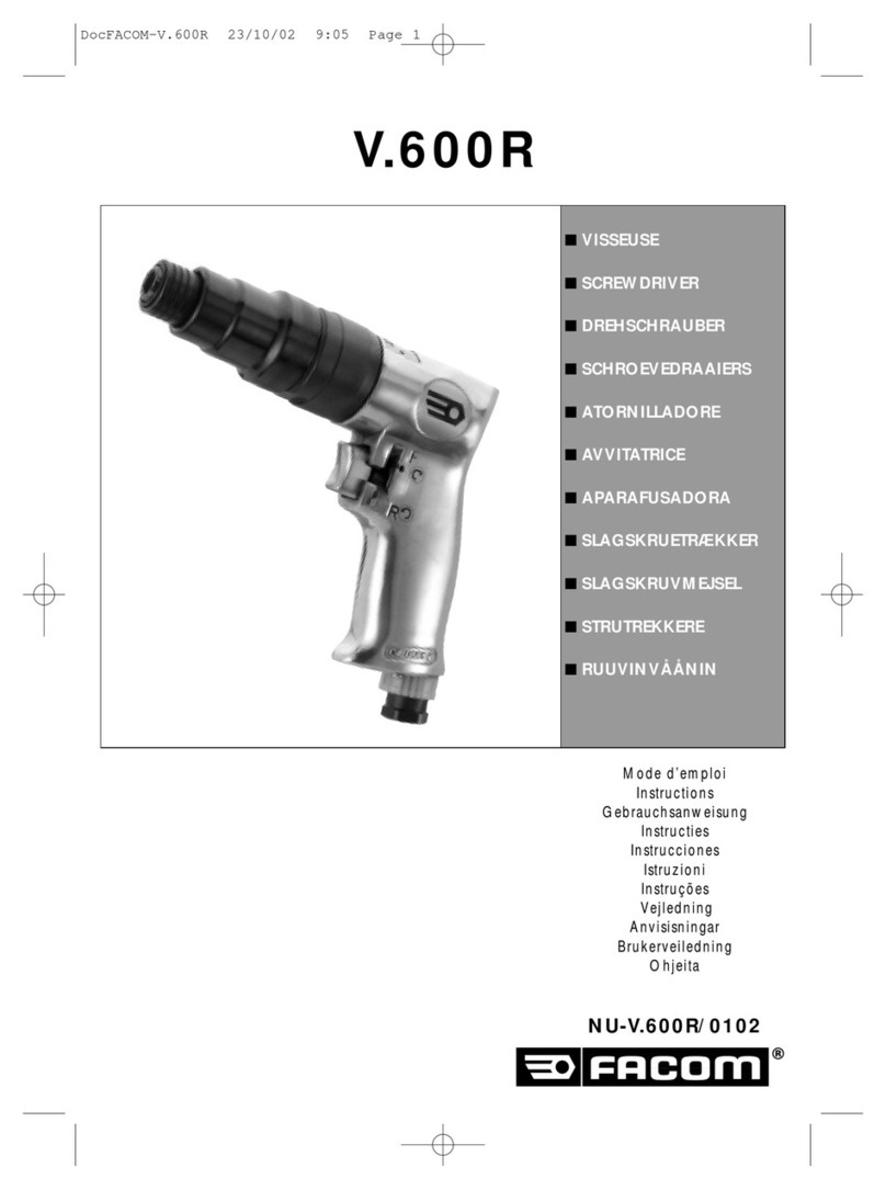
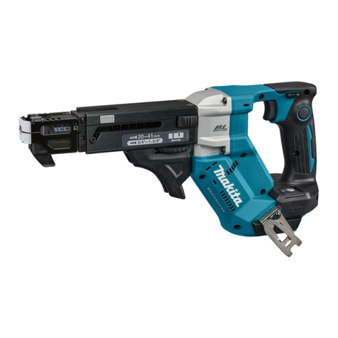
Makita DFT087F Operating instructions

August 2022
Ver.1
OFFICIAL USE
For ASC
CORDLESS SCREWDRIVER
DFT087F, DFT129F
REPAIR MANUAL

2 / 35
1CONTENTS
1CONTENTS.................................................................................................................................................................................2
2CAUTION....................................................................................................................................................................................3
3NECESSARY REPAIRING TOOLS ...........................................................................................................................................3
4LUBRICANT AND ADHESIVE APPLICATION ......................................................................................................................3
5TIGHTENING TORQUE SPECIFICATIONS............................................................................................................................3
6REPAIR ........................................................................................................................................................................................4
6-1 Bit sleeve section..................................................................................................................................................................4
6-1-1 Disassembling .............................................................................................................................................................4
6-1-2 Assembling..................................................................................................................................................................4
6-2 Electrical parts section..........................................................................................................................................................5
6-2-1 Disassembling .............................................................................................................................................................5
6-2-2 Assembling..................................................................................................................................................................7
6-3 Clutch assembly section.....................................................................................................................................................10
6-3-1 Disassembling ...........................................................................................................................................................10
6-3-2 Assembling................................................................................................................................................................ 11
6-4 Gear assembly section........................................................................................................................................................13
6-4-1 Disassembling ...........................................................................................................................................................13
6-4-2 Assembling................................................................................................................................................................13
7CIRCUIT DIAGRAM................................................................................................................................................................15
8WIRING DIAGRAM.................................................................................................................................................................16
8-1 LED circuit section ............................................................................................................................................................16
8-2 Electrical parts section........................................................................................................................................................17
9-1 Models those Housing L with Opening A..........................................................................................................................18
10 TROUBLESHOOTING.............................................................................................................................................................19
10-1 Note for Repairing .............................................................................................................................................................19
10-2 Test for checking the short-circuit in FET (Field Effect Transistor) of controller ..............................................................19
12 CHECK LIST FOR TROUBLESHOOTING ............................................................................................................................20
13 APPROXIMATE ENDURANCE TIME OF EACH PART.......................................................................................................31
14 MAIN FEATURES OF THE MACHINE..................................................................................................................................32
15 SPECIFICATIONS OD BATTERY...........................................................................................................................................32
16 LISTS OF THE ELECTRONIC FUNCTIONS AND REMAINDERS ....................................................................................33
16-1 When a screw is tightened completely or when there is no trouble with the machine: ......................................................33
16-2 When a screw is tightened incompletely or when there is some trouble with the machine:...............................................33
16-3 When tightening the tightened screw again: ......................................................................................................................34
16-4 During USB communication..............................................................................................................................................34
17 TORQUE CHECK MODE ........................................................................................................................................................34
17-1 How to use “Torque check mode”. ....................................................................................................................................34
17-2 How to cancel “Torque check mode”.................................................................................................................................35
18 USING THE DEDICATED APP (MAKITA INDUSTRY TOOL SETTINGS) ........................................................................35

3 / 35
2CAUTION
Repair the machine in accordance with "Instruction manual" or "Safety instructions".
Follow the instructions described below in advance before repairing:
Wear gloves.
In order to avoid wrong reassembly, draw or write down where and how the parts are assembled, and what the parts are.
It is also recommended to have boxes ready to keep disassembled parts by group.
Handle the disassembled parts carefully. Clean and wash them properly.
Remove Battery, except when it is necessary to check the operation of the machine.
3NECESSARY REPAIRING TOOLS
Code No.
Description
Use for
1R003
Retaining ring pliers ST-2N
removing/assembling Ring spring 9 and Retaining ring S-10
1R212-A
Plier tip for 1R004 small
using with 1R003
1R212-B
Plate set with screws
1R288
Screwdriver magnetizer
magnetizing screwdriver
1R411
Push bar for lead wires
fixing Lead wires
1R479
Shockless hammer (Small)
press-fitting Hex nut M3 (a component of Housing R)
4LUBRICANT AND ADHESIVE APPLICATION
Description
Amount
Makita grease GA No.2
Apply a little unless specified in the figure.
Lubricant No.101
a little
Fig. 1
5TIGHTENING TORQUE SPECIFICATIONS
Parts to fasten
Fastener
Tightening torque (N∙m)
Housing L
↔
Housing R
Lock nut M28 black
2.0 - 3.0
Housing L
↔
Housing R
Pan head screw M3x20
0.4 - 0.6
↔
Cover
Pan head screw M3x10
1g
DFT129F

4 / 35

6REPAIR
6-1 Bit sleeve section
6-1-1 Disassembling
Fig. 2
1Remove Ring spring 9 [1] with 1R003, 1R212-A
and 1R212-B.
2Remove Flat washer 10 [2], Compression spring 10
[3] and Bit sleeve [4].
Fig. 3
3Remove Steel balls 2.4 [2] (2 pcs) with a thin
slotted screwdriver [1].
Tips
Remove Steel balls 2.4 [2] (2 pcs) by picking them
out with a screwdriver or the like magnetized with
1R288.
6-1-2 Assembling
Fig. 4
1Assemble Steel balls 2.4 [2] (2 pcs) with a thin
slotted screwdriver [1].
Tips
Apply some grease to Steel balls 2.4 [2] (2 pcs.) so as
not to fall off them.
Fig. 5
2Assemble the following parts, then assemble Ring
spring 9 [1] with 1R003, 1R212-A and 1R212-B.
Bit sleeve [2]
Compression spring 10A [3]
Flat washer 10 [4]
Note
Insert a bit and check that the bit can be attached or
detached properly.
[1]
[2]
[3]
[4]
1R003
1R212-A
[4]
[1]
[2]
[1]
[2]
[1]
[4]
[3]
[2]
1R003
1R212-A
[2]

5 / 35
6-2 Electrical parts section
6-2-1 Disassembling
1Disassemble Bit sleeve section. (6-1-1)
Fig. 6
2Remove Lock nut M28 black [2] with a 30mm
socket [1] by turning it counterclockwise, then
remove O-ring 22 [3].
Fig. 7
3Remove Pan head screw M3x10 [1], then remove
Cover [3] from Housing L [2].
4Disconnect Connector when Unit (Herutu’s
module) [4] is used.
Fig. 8
5Remove Pan head screws M3x20 [1] (8 pcs), then
remove Housing L [2].
Note
Be careful not to fall off Hex nuts M3 (8 pcs) from
Housing R.
Fig. 9
6Remove the following parts from Housing R [1]:
Change plate [2]
Compression spring 2 [3]
Switch lever [4]
Plate H (DFT087F)/Plate I (DFT129F) [5]
Clutch assembly 8M (DFT087F)/Clutch assembly
12M (DFT129F) [6] (Clutch assemblies can be
removed by lifting up Gear assembly [7] and Motor
section [8] slightly.)
USB cover [9]
[3]
[2]
[1]
[1]
[3]
[2]
[4]
[3]
[1]
[2]
[2]
[5]
[6]
[1]
[3]
[4]
[9]
[7]
[8]

6 / 35
Fig. 10
7Remove Gear assembly [2] and Rotor [3] from
Housing R [1].
Fig. 11
8Remove the following parts from Housing R [1]:
F/R change lever [2]
Lens, LED circuit [3]
LED circuit [4]
Stator [5]
Sensor circuit [6]
USB circuit [7]
Switch [8]
Buzzer circuit [9]
Controller [10]
Terminal [11]
9Disconnect Connectors and Receptacles.
Fig. 12
10 Remove Tapping screws PT 2x6 [2] (3 pcs) from
Stator [1] with a No.1 Phillips screwdriver, then
remove Circuit board [3].
Note
Be careful not to strip the head of Tapping screw PT
2x6 [2].
Fig. 13
11 Remove Flat head screws M3x6 [2] (3 pcs) from
Stator [1] with a No.1 Phillips screwdriver, then
remove Terminal unit [3].
Note
Be careful not to strip the head of Flat head screws
M3x6 [2] (3 pcs).
Remove Terminal unit [3] straight while being
careful not to deform Thermistor connection
terminals [4].
[1]
[3]
[2]
[1]
[4]
[6]
[8]
[3]
[7]
[5]
[2]
[9]
[10]
[11]
[3]
[2]
[1]
[2]
[3]
[1]
[4]

7 / 35
6-2-2 Assembling
1Assemble Clutch assembly and Gear assembly. (6-3-2, 6-4-2)
Fig. 14
2Assemble Terminal unit [2] to Stator [1], then
tighten Flat head screws M3x6 [3] (3 pcs) with a
No.1 Phillips screwdriver.
Note
Be careful not to strip the head of Flat head screws
M3x6 [3] (3 pcs).
Connect Terminal unit [2] straight with care not to
deform the terminals [4] of Thermistor connection.
Fig. 15
3Assemble Circuit board [2] to Stator [1], then
tighten Tapping screws PT 2x6 [3] (3 pcs) with a
No.1 Phillips screwdriver.
4Assemble the electrical parts in accordance with
Circuit diagram and Wiring diagram.
Note
Be careful not to strip the head of Tapping screw PT
2x6 [3].
Fig. 16
5Assemble the following parts to Housing R [1],
then fix Lead wires with 1R411.
Controller [2]
Terminal [3]
Buzzer circuit [4]
Switch [5]
LED circuit [6]
Sensor circuit [7]
F/R change lever [8]
Lens, LED circuit [9]
USB circuit [10]
Fig. 17
6Assemble Rotor [2] and Gear assembly [3] to Stator
[1], then assemble them to Housing R [4].
Note
Assemble Rotor [2] to Stator [1] while putting Stator
[1] on a workbench, because the excessive pushing
Rotor [2] to Stator [1] may cause the break of Printed
circuit board.
[3]
[2]
[1]
[4]
[2]
[3]
[1]
[1]
[6]
[7]
[8]
[9]
[3]
[2]
[4]
[5]
[10]
[1]
[2]
[3]
[4]

8 / 35
Fig. 18
7Assemble Clutch assembly 8M (DFT087F)/Clutch
assembly 12M (DFT129F) [2] while lifting up Gear
assembly [1] slightly, then assemble them to
Housing [3].
Fig. 19
8Assemble the following parts to Housing R [1]:
Change plate [2]
Note
Move Change plate [2] to Motor side.
Compression spring 2 [3]
Switch lever [4]
USB cover [5]
Note
Stay USB cover [5] close.
Plate [6]
Note
Assemble Plate [6] so that its surface with numerical
value faces Housing L [7].
Fig. 20
9Assemble Housing L [1] with Pan head screws
M3x20 [2] (8 pcs).
Note
If Hex nuts M3 fall off from Housing R, tighten Pan
head screw M3x20 [2] approximately 2 times, then
press-fit Hex nuts M3 by tapping them with 1R479.
Pass Connector through Housing L [1] if Unit
(Herutu module) is used.
[1]
[2]
[3]
[2]
[5]
[1]
[3]
[4]
[6]
[7]
[2]
[1]

9 / 35
Fig. 21
10 Connect Connector if Unit (Herutu’s module) [1] is
used.
11 Assemble Cover [3] to Housing L [2] with Pan
head screw M3x10 [4].
Fig. 22
12 Assemble O-ring 22 [1].
Fig. 23
13 Tighten Lock nut M28 black [2] to the specified
torque by turning a 30mm socket [1] clockwise.
[4]
[3]
[2]
[1]
[3]
[1]
[1]
[2]
[1]

10 / 35
6-3 Clutch assembly section
6-3-1 Disassembling
1Disassemble the electrical parts. (6-2-1)
Fig. 24
2Remove Retaining ring S-10 [1] with 1R003, then
remove Ball bearing 6800LLB [2], Compression
spring 10B [3] and Flat washer 10 [4].
Fig. 25
3Loosen Lock nut M12 [2] by using Adjust grip [1]
until it gets loose.
4Remove Adjust spring [3] by turning Lock nut M12
[2] (Left-handed) clockwise.
Fig. 26
5Remove Flat washer 18 [1] and Compression
spring 19E (DFT087F)/Compression spring 19C
(DFT129F) [2].
Fig. 27
6Remove Steel balls 4 [1] (7 pcs), then remove Cam
F [2].
[1]
1R003
[2]
[3]
[4]
[2]
[1]
[2]
[3]
[1]
[2]
[1]
[2]
[1]
[2]

11 / 35
Fig. 28
7Remove Steel balls 4 [1] (3 pcs) and Steel balls 5.0
[2] (3 pcs), then remove Cam D [3].
6-3-2 Assembling
Fig. 29
1Assemble Cam D [2] to Spindle [1].
Note
Apply the specified grease to the threads of Spindle
[1].
Fig. 30
2Assemble the following parts to Cam D [1] and
Spindle [2]:
Steel balls 4 [3] (3 pcs)
Steel balls 5.0 [4] (3 pcs)
Cam F [5]
Note
Apply the specified grease to the following parts:
Steel ball 4 [3]
Steel ball 5 [4] (for fall-off prevention)
The cam portion of Cam F [5]
Fig. 31
3Assemble Steel balls 4 [3] (7 pcs) between the
groove of Spindle [1] and the depression of Cam F
[2].
Note
Apply the specified grease to Cam F [2] and Steel
balls 4 [3] (7 pcs).
[1]
[3]
[2]
[1]
[2]
[1]
[3]
[2]
[4]
[5]
[1]
[2]
[3]

12 / 35
Fig. 32
4Assemble Compression spring 19E
(DFT087F)/Compression spring 19C (DFT129F)
[2] and Flat washer 18 [3] to Spindle [1].
Fig. 33
5Assemble Adjust ring [2] to Spindle [1].
Fig. 34
6Screw Lock nut M12 [2] (Left-handed) to Spindle
[1] by turning it counterclockwise.
Fig. 35
7Assemble the following parts to Spindle [1], then
assemble Retaining ring S-10 [2] with 1R003.
Flat washer 10 [3]
Compression spring 10B [4]
Ball bearing 6800LLB [5]
[3]
[2]
[1]
[3]
[2]
[1]
[2]
[1]
[2]
[1]
[2]
[5]
[4]
[3]
[5]
1R003

13 / 35
6-4 Gear assembly section
6-4-1 Disassembling
1Disassemble the electrical parts. (6-2-1)
Fig. 36
2Remove Motor bracket [2] from Gear case [1] by
turning it counterclockwise, then remove the
following parts:
Lock washer [3] (Lock washer can be removed by
inserting a thin screwdriver or the like into the hole of
it and turn it counterclockwise.)
Spur gears 18 (DFT087F)/Spur gears 14 (DFT129F)
[4] (3 pcs)
Spur gear 20 complete A (DFT087F)/Spur gear 17
complete B (DFT129F) [5]
Spur gears 13 (DFT087F)/Spur gears 19 (DFT129F)
[6] (3 pcs)
Internal gear 47 [7]
Carrier A (DFT087F)/Carrier C (DFT129F) [8]
Ball bearing 6805LLB [9]
Needle cages 205 [10] (3 pcs, DFT129F only)
6-4-2 Assembling
Fig. 37
1Assemble Ball bearing 6805LLB [2] to Carrier A
(DFT087F)/Carrier C (DFT129F) [1].
Fig. 38
2Assemble Gear case [1] and Internal gear 47 [2].
(Fig. 37)
Fig. 39
3Assemble Spur gears 13 (DFT087F)/Spur gears 19
(DFT129F) [2] (3 pcs) to the pins of Carrier A
(DFT087F)/Carrier C [1] (DFT129F) [1].
Note
Apply the specified grease to the pins of Carrier A
(DFT087F)/Carrier C (DFT129F) [1] (3 pcs) and the
inner teeth of Internal gear 47 [3].
[8]
[9]
[1]
[7]
[6]
[5]
[4]
[3]
[2]
[10]
[2]
[1]
[1]
[2]
[2]
[1]
[3]

14 / 35
Fig. 40
(DFT087F)
4Assemble Spur gear 20 complete A [1], then
assemble Spur gears 18 [2] (3 pcs).
Note
Apply the specified grease to the pins (3 pcs) of Spur
gear 20 complete A [1] and the inner teeth of Internal
gear 47 [3].
Fig. 41
(DFT129F)
5Assemble Needle cages 205 [2] (3 pcs) and Spur
gears 19 [3] (3 pcs) to the pins (3 pcs) of Spur gear
17 complete B [1].
Note
Apply the specified grease to Needle cages 205 [2] (3
pcs) and the inner teeth of Internal gear 47 [4].
Fig. 42
6Assemble Lock washer [2] to Gear case by aligning
it with the groove of Gear case [1], then assemble
them by turning Lock washer [2] clockwise.
7Similarly, assemble Motor bracket [3] by turning it
clockwise.
Tips
Insert Lock washer [2] and Motor bracket [3] into the
smaller notch of Gear case [1].
[2]
[1]
[3]
[3]
[2]
[1]
[1]
[4]
[2]
[3]
[1]

15 / 35
7CIRCUIT DIAGRAM
Fig. 43
1
AWG14
11
USB circuit
2
AWG16
12
LED circuit B
3
AWG22
13
Buzzer circuit
4
Terminal
14
Sensor circuit
5
Flag receptacle with lock (#250, t=0.8)
15
LED circuit A
6
Flag receptacle with lock (#187, t=0.8)
16
Sensor board
7
Connector
17
Terminal unit
8
Connector for Herutu’s module
18
Controller
9
Switch
19
Circuit diagram of Switch
10
Line filter
20
Reversing switch
スイッチ回路図
1
2
7
8
3
4
9
10
5
6
12
14
11
13
15
16
17
18
1
7
7
7
7
7
7
19
20

16 / 35
8WIRING DIAGRAM
8-1 LED circuit section
Fig.44
1
Rib A
5
Sensor circuit
2
Housing R
6
F/R change lever
3
LED circuit B
7
USB circuit
4
LED circuit A
8
Place LED circuit B so that its lead wires come out from the bottom of Housing R.
9
Route LED circuit A lead wires/Sensor circuit lead wires between Rib A and F/R change lever.
10
Be careful not to put Lead wires on/under Sensor circuit.
11
Be careful not to put LED circuit B lead wires on this rib.
12
Fix LED circuit A lead wires in these grooves.
13
Fix USB circuit lead wires and LED circuit B lead wires in this groove.
14
Fix LED circuit A lead wires and Sensor circuit lead wires in this groove.
1
2
7
3
4
5
6
8
12
13
14
9
10
11

17 / 35
8-2 Electrical parts section
Fig.45
1
LED circuit A
8
Line filter
2
Sensor circuit
9
Connector (for LED circuit A, LED circuit B, Sensor circuit,
USB circuit and Buzzer circuit)
3
Stator
10
Connector with Tape
4
LED circuit B
11
Protrusion of Controller
5
USB circuit
12
Space A
6
Switch
13
Controller
7
Buzzer circuit
14
Connector (3-pin/No connection)
15
Fix the following Lead wires in this groove:
LED circuit A lead wires/LED circuit B lead wires/Sensor circuit lead wires/USB circuit lead wires/Lead wires for Stator
16
Be careful not to put Lead wires on/under Buzzer circuit.
17
Place Line filter, Connector (for LED circuit A, LED circuit B, Sensor circuit, USB circuit and Buzzer circuit) and Connector with Tape
in Space A.
18
Be careful not to put Lead wires under the protrusion of Controller.
19
Place Connector (3-pin/No connection) in Space A if there is no opening A in Housing L (See next page.).
1
2
7
8
3
4
9
10
5
6
12
14
11
13
15
16
17
18
19

18 / 35
9-1 Models those Housing L with Opening A
Fig.46
1
Connector (3-pin/No connection)
3
Housing L
2
Opening A
4
Space B
5
Place Connector (3-pin/No connection) in Opening A.
6
Pass Connector (3-pin/No connection) lead wires through Opening A.
7
Be careful not to put Connector (3-pin/No connection) and Lead wires on this rib (hatched portion).
8
Be careful not to put the slack of Connector (3-pin/No connection) lead wires on Space B.
1
2
3
4
8
5
6
7

19 / 35
10 TROUBLESHOOTING
Whenever you find any trouble in your machine, first, see this list to check the machine for solution.
10-1 Note for Repairing
The content may vary depending on the model.
1Use a full charged battery which has a star mark.
2When Housing is disassembled, check the conditions of the electrical parts (Connectors, Lead wires, Switches, etc.),
Rotor, Stator, Gear section, etc.
3Be sure to test the machine 10 times to correctly diagnose functions such as F/R control etc.
4Use the following Repairing tools for diagnosing LED and Switch.
Repairing tools
Purpose
1R402
For checking variable resistance value or electrical continuity at contact points
1R402-B
1R412
For checking whether LED lights up
1R413
For checking variable resistance value or electrical continuity at contact points
10-2 Test for checking the short-circuit in FET (Field Effect Transistor) of controller
Fig. 47
1Set Digital tester (1R402) to Diode mode.
Fig. 48
2Connect Black probe to the plus pole of Terminal,
and Red probe to the minus pole.
Tips
By attaching 1R402-B to each probe of 1R402, you
can make your hands free for easier check.
Note
Be careful not to reverse them. The reversed contacts
could spoil the test.
3Wait until the figure on Tester gets stable. Controller is in order if Tester indicates 1.1±0.2V. If Tester indicates
any other voltage, Controller is broken. Replace it with a new one.
1R402-B

20 / 35
12 CHECK LIST FOR TROUBLESHOOTING
Check the items in the following flowchart in order from the top to bottom. Description of
each item is referred to CIRCUIT DIAGRAM.
∙ After corrective action, return to the start of Troubleshooting and re-check again.
∙ The machine settings using App. should be checked with factory manufactured condition.
If the machine is used App and cannot change the settings, replace "Controller" or "USB
Circuit".
How to follow arrows
Yes
No
Symptom
Corrective action
What to check
Occasionally no rotation
Clutch does not work.
Poor torque precision
Rotating even if Clutch works.
Abnormal noise
Absolutely no rotation
See page 22.
Check if LED job light, Buzzer and LED
indicator work properly when the battery is
inserted.
LED job light, Buzzer and LED
indicator do not work properly.
Remove Gear assembly, and then see whether
Motor rotates independently.
Slow rotation
LED job light does not light up when the
battery is inserted.
Buzzer does not beep when the battery is
inserted.
LED indicator (red/green) does not light up
when the battery is inserted.
Note: Be sure to connect Motor bracket to Rotor.
Remove Gear assembly, and then check if
Motor makes abnormal noise.
See page 22.
See page 23.
See page 23.
See page 24.
See page 24.
See page 24.
See page 22.
See page 25.
See page 26.
See page 26.
See page 26.
See page 26.
Other manuals for DFT087F
4
This manual suits for next models
1
Table of contents
Other Makita Power Screwdriver manuals

Makita
Makita 6822 User manual

Makita
Makita 6802BV User manual

Makita
Makita FS4000 User manual

Makita
Makita BFT043F Manual

Makita
Makita 6823TP User manual

Makita
Makita 6836 Manual

Makita
Makita DFT060T User manual

Makita
Makita ELECTRIC BRAKE 6094DW User manual

Makita
Makita DFL020F User manual

Makita
Makita 6842 User manual

Makita
Makita 6802BV User manual

Makita
Makita DTS131RTJ User manual

Makita
Makita 6807 User manual

Makita
Makita FS4300 Manual

Makita
Makita 6826 User manual

Makita
Makita DFT060T User manual

Makita
Makita DFL083F User manual

Makita
Makita FS2700 User manual

Makita
Makita 6705D User manual

Makita
Makita FS2500 User manual