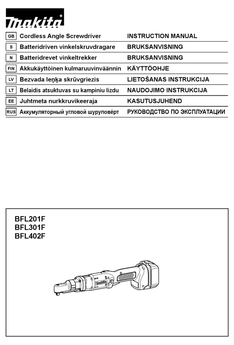
Makita BFL301F Manual

Specification
Standard equipment
Optional accessories
Model No.
Description
PRODUCT
CONCEPT AND MAIN APPLICATIONS
P 1/ 14
TECHNICAL INFORMATION
Battery BL1430
Battery BL1430A
Fast charger DC18RA
Charger DC18SD
Charger DC24SC
Automotive Charger DC18SE
Auto refresh adapter ADP03
Battery protector (for BL1430A)
Protectors (red/ blue/ yellow/ clear)
Torque adjust tool
Dimensions: mm (")
Width (W)
Height (H)
Length (L) 477 (18-3/4)
98 (3-7/8)
72 (2-13/16)
Model No. BFL402FBFL301F
BFL301F, BFL402F
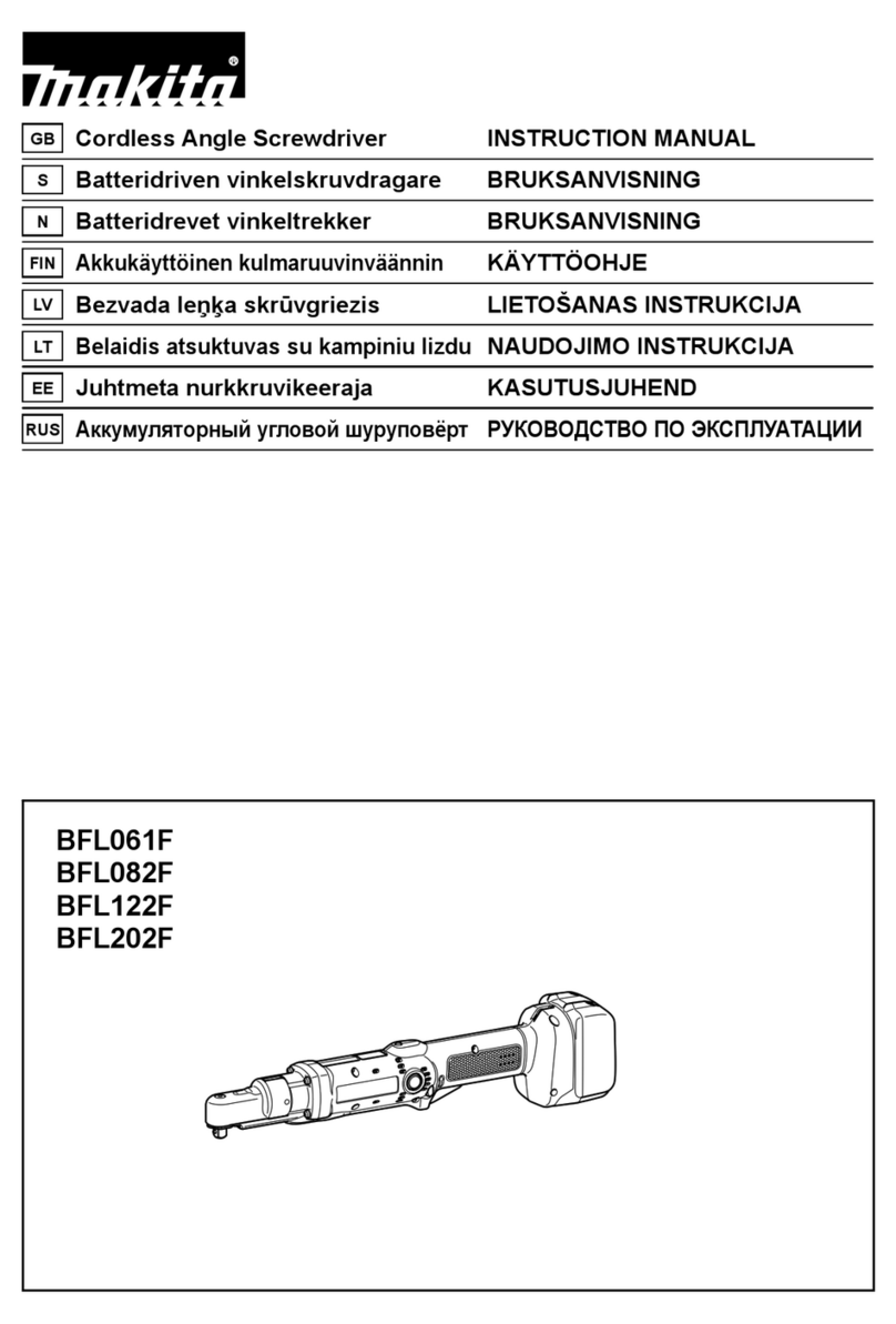
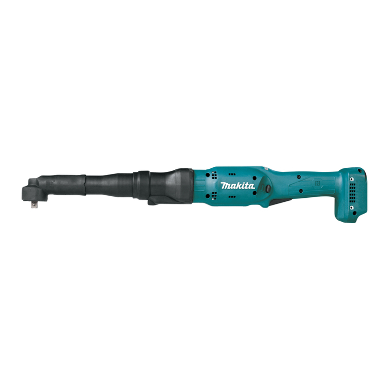
Cordless Angle Screwdriver 14.4V
These cordless angle screwdrivers for fastening works in assembling line
are developed as advanced models of BFL300F, BFL400F.
Additionally to the same tool durability and high fastening torque accuracy
as the current series models, these products feature a powerful and efficient
power source and power unit, namely 14.4V/ 3.0Ah Li-ion battery*and
BLDC motor (Brushless DC motor).
*Compatible with BL1430 and BL1430A but not with 1.3Ah Li-ion battery BL1415
BFL402F
Model
Specifications
No load speed: rpm= min-1 200260
315 370
2.0 (4.4)
Battery
Driving shank: mm (")
Weight according to
EPTA-Procedure 01/2003*: kg (lbs)
LED Job light
Torque adjustment
Reversing switch
Electric brake
Soft start
Fastening torque range: N.m (in.lbs) 25 - 40 (221 - 354)
BFL301F
16 - 30 (142 - 266)
Yes
Yes
Yes
Yes
Yes
9.5 (3/8) Square
Cell
Voltage: V
Capacity: Ah
Li-ion
14.4
3.0
Max output: W
*with Battery BL1430
These products are available in the following specifications
with the model numbers described below.
L
H
W
(model BFL301F)
No
Note: The standard equipment for the tool shown above may vary by country.

P 2/ 14
[1] NECESSARY REPAIR TOOLS
Repair
Code No. Description Use for
1R004 Retaining ring pliers ST-2
removing Retaining ring S-10 and S-14
1R005
1R008
1R291 Retaining ring S and R pliers
Retaining ring pliers RT-2N removing Retaining ring R-32, R-22 and R-26
1R034 Bearing setting plate 12.2 press fitting Ball bearing 6900LLB and 6000DDW
1R145
1R314
1R173
L type torx wrench set (T25)
765027-4 Torque adjust tool
Retaining ring R pliers
1R269 Bearing extractor
1R288 Screwdriver magnetizer
Hex wrench 6
Torx bit VT-25
disassembling Clutch section (M5x10 Torx C. S head screw)
assembling Clutch section, Bearing retainer and Hex nut M36-41
at designated tightening torque
fitting Retaining ring R-22
extracting Ball bearing 6900LLB and 6000DDW
magnetizing Screwdriver
1R219 Torque wrench shaft 7-23N.m
1R220 Ratchet head 9.5 (for 1R219)
1R222 Socket adapter (for 1R219)
1R223 Torque wrench shaft 20-90N.m
Socket 32-50
1R341 Spanner head 41 (for 1R223)
Tips for Retaining ring pliers
BFL301F
Model No.
Description
Item No.
Ring 38 Ring 38L Ring 38K
Compression spring 19 Compression spring 19F Compression spring 19B
Spur gear 20 complete Spur gear 20 complete C Spur gear 20 complete A
Clutch ass’y I Clutch ass’y J
Gear ass’y E Gear ass’y A
Gear ass’y (as an option for quick
repair of Gear section) consists of
Item Nos.
Clutch ass’y (as an option
for quick repair of Clutch
section) consists of Item Nos.
27
41
59
60
BFL402F
CAUTION: Repair the machine in accordance with “Instruction manual” or “Safety instructions”.
Note: Some parts numbers and descriptions differ from model to model. Refer to the following list and replace the
descriptions in this technical information.
Plate Plate J Plate K1
52
Spur gear 15/ 18 Spur gear 15 Spur gear 1853
36 37 38 39 40 41
42 43 44 45 46 47
4948 50 51 52 53 54 55 56

P 3/ 14
11
2221
31
62
64
39 40 43 45 48 51 52 53
10
63
Repair
47
Item No. Description Lubricant Amount
3.8g in total
2g in total
a little
Portion to lubricate
Item No. Description
: Makita grease N. No.2
: Loctite 603
: Seal lubricant No.101
Angle head complete
Spiral bevel gear 9
Spindle A complete
Spur gear 21
11
10
Bearing retainer 18-30 Threaded portion
Threaded portion
64
M5x10 Torx C.S. head screw
47
62
31
Spur gear 14 (5pcs.)
O ring 18
Spindle39
22
63
Gear teeth
Apply the following lubricants to protect parts and product from unusual abrasion.
Apply Loctite 603. (Fig. 1)
[2] LUBRICANT AND ADHESIVE APPLICATION
LUBRICANT
Gear room
Seal lubricant
No.101
(042010-1A: 100g)
Gear teeth
Gear teeth
Whole portion
Outside thread
Steel ball 5.0 (3pcs.)40
Steel ball 4 (3pcs.)43 Whole portion
Gear teeth
Gear teeth
Steel ball 3 (13pcs.)45
Carrier A complete A48
Spur gear 13 (3pcs.)51
Spur gear 20 complete52
Spur gear 15/ 18 (3pcs.)53
11
hole to receive Shaft end of
Teeth portion
Pin 3 (5pcs.)
21 Whole portion
Portion to apply adhesive
Fig. 1
Makita grease
N. No.2
ADHESIVE
Gear teeth and Pin portions
Pin portions

[3] DISASSEMBLING/ ASSEMBLING
[3] -1. Disassembling/ Assembling of Job Light Section
DISASSEMBLING
(1) Remove Lead cover by removing Ring spring 36, and Ring spring 29 with a slotted screwdriver. (Figs. 2, 3 and 4)
(2) Remove Light covers (R) and (L) while pushing the portion designated by the gray circle to unlock the tab on
Light cover (R) from the slot of Light cover (L). (Fig. 5)
(3) Separate Switch cover from the tool by removing two M4x8 Pan head screws.
(4) Remove Lead wires and LED circuit from Lead wire holders and Light cover (R), and disconnect Connector. (Fig. 6)
Pan head screw M4x8
(for fixing Switch cover)
M4x8 Pan head screw (for fixing Ring 38)
Ring spring 29
Ring spring 36
Light cover (L)
Lead cover Switch cover
Fig. 2
Fig. 3 Fig. 4 Fig. 5
Fig. 6 Fig. 7
ASSEMBLING
(1) Fix Lead wires securely in Lead wire holders and then install LED circuit on Light cover (R).
At this time, make a slack of Lead wires in place as the right illustration in Fig. 6.
(2) Push the tab on Switch cover into the cut in Housing before fastening screws. And then fix Switch cover with two
M4x8 Pan head screws. Do not pinch the Lead wires in this step. (Figs. 2, 7)
(3) Install Light covers (R) and (L) while locking the tab on Light cover (R) in the slot in (L), then Ring spring 29. (Fig. 5)
Ring spring 29 can be easily installed by fixing one end on the groove in Light cover, then pushing toward Light cover
while expanding the other end. (Fig. 8)
(4) Fix Lead cover and Ring spring 36 carefully so as not to pinch the Lead wires from LED circuit. (Fig. 9)
Push the end face of Lead cover using a slotted
screwdriver till it is lifted up and remove Lead cover
by pulling it to the described direction below.
Push here.Ring spring 29
LED circuit Lead wire holders
Switch cover tab
Make a slack of Lead wires
in this portion.
tab
Light cover (R)
P 4/ 14
Repair
Fig. 8 Fig. 9
Ring spring 29
Lead cover
Lead wire
Ring spring 36

[3] -2. Disassembling/ Assembling of Bearing Retainer
Fig. 11
Fig. 10
DISASSEMBLING
ASSEMBLING
(1) Put O ring 18 in Bearing retainer after applying Seal lubricant No.101
and fix Spindle complete to Bearing retainer.
(2) Apply 2 g of Seal lubricant No.101 in the gear room of Angle head complete.
Do not let the lubricant touch to the threaded portion of Angle head complete in this step.
(3) Apply Loctite 603 to the threaded portion of Bearing retainer and screw it into Angle head complete.
In this step, remember to put Flat washer 5 to Spindle complete.
(4) Fasten Bearing retainer to the recommended torque of 50 - 70N.m by turning counterclockwise with the following
tools;
1R223, 1R220, 1R222, A-43424.
Turn Bearing retainer clockwise using a spanner. of 32mm jaw capacity.
Now Bearing retainer can be removed by pulling it down. (Fig. 10).
DISASSEMBLING
(1) Remove Light covers (R) and (L), Ring spring 29, Lead cover and Switch cover. (Refer to [3] -1.)
(2) Grip two flats of Angle head by using wrench or vise and remove Hex nut M36-41 by turning counterclockwise with
1R223 and 1R341. (Figs. 12 and 13)
Caution: Do carefully clamp Angle head so as not to deform it by overtightening.
(3) Remove Angle head complete by turning counterclockwise.
(4) Remove Retaining ring R-32 by using 1R005, then Flat washer 26, Internal gear 50 and Carrier section.
(5) Remove Retaining ring S-14 from Carrier section using 1R291 or the like. Now the following parts can be replaced;
Flat washer 14, Pin 3 (5pcs), Spur gear 14 (5pcs)
Note: Pin 3 can be pulled out easily by using Screwdriver magnetized by 1R288.
(6) Remove Retaining ring R-22 located inside Angle head complete using 1R005.
(7) Remove Spiral bevel gear 9 section by hitting the end face of Angle head complete. (Fig. 14)
(8) Remove Retaining ring S-10 from Spiral bevel gear 9 section using 1R004, 1R008 or the like.
Now the following parts can be replaced by removing Ball bearing 6900LLB with 1R269 or the like:
Spiral bevel gear 9, Spacer, Thin washer 12, Needle bearing 1212
Bearing retainer
[3] -3. Disassembling/ Assembling/ Adjustment of Angle Head Section
10) Angle head complete
11) Spiral bevel gear 9
12) Needle bearing 1212
13) Thin washer 12
14) Spacer
15) Ball bearing 6900LLB
16) Retaining ring S-10
17) Retaining ring R-22
18) Internal gear 50
19) Retaining ring S-14
20) Flat washer 14
21) Pin 3 (5pcs)
22) Spur gear 14 (5pcs)
23) Carrier
24) Flat washer 26
25) Retaining ring R-32
*Shown in Fig. 11 are the parts of Angle head section.
10
11 12 13 14 15 16 17 18 19 20 23 24 25
21 22
Spiral bevel gear 9 section Carrier section
P 5/ 14
Repair
Fig. 12 Fig. 13 Fig. 14
Angle head complete
two flats
Adjustable wrench
No.1R223
No.1R341

[3] -4. Disassembling/ Assembling of Clutch Case Section
ASSEMBLING
(1) Assemble Needle bearing 1212, Thin washer 12 and Spacer to Spiral
bevel gear 9.
Caution: Spacer is not reversible when assembled to Spiral bevel gear 9.
Be sure to place as drawn in Fig. 11.
(2) Press-fit Ball bearing 6900LLB to Spiral bevel gear 9 using arbor press
and 1R034. Assemble Retaining ring S-10 to Spiral bevel gear 9.
And then insert Spiral bevel gear 9 section into Angle head complete.
(3) Assemble Retaining ring R-22 to Spiral bevel gear 9.
(4) Put Internal gear 50 in Angle head complete so that the protrusions on
Internal gear 50 fit in the matching holes on Angle head complete.
(Fig. 15)
(5) Assemble Spur gear 14 and Pin 3 (5pcs. each) to Carrier, and then
Thin washer 14 and Retaining ring S-14 to complete Carrier section.
(6) Insert Carrier section into Angle head complete, and apply 1.5g of Seal lubricant No.101 to Spur gear 14.
(7) Put Flat washer 26 and fix Retaining ring R-32 using 1R005.
DISASSEMBLING
*Shown in Fig. 16 are the parts of Clutch case
section.
(1) Remove Angle head section. (Refer to [3]-1, 3.)
(2) Remove Compression spring 2 and Switch lever.
(3) Clutch case, Clutch assembly and Compression
spring 5 can be removed by removing four
M4x22 Pan head screws.
(4) Remove Retaining ring R-26 using 1R291.
(5) Push out Spur gear 21 and remove Flat washer 21
using slotted screwdriver.
Then, push out Ball bearing 6803ZZ.
(6) Remove Retaining ring S-10 with 1R004 or 1R008
and Ball bearing 6000DDW using 1R269. Now
Spur gear 21 can be replaced.
(7) Remove Hex nut M36-41 by turning
counterclockwise. Clutch case can be replaced
after removing Ring 38.
ADJUSTMENT
(1) Fasten Angle head complete and Hex nut M36-41 to Clutch case section fully by hand.
(2) Turn Angle head complete counterclockwise to adjust to a desired angle.
(3) Tighten Hex nut M36-41 clockwise with 1R223 and 1R341 to the recommended torque of 30 -50N.m while paying
attention not to change the position of Angle head.
(4) Make sure that Lead wires are fixed in place with Lead wire holders as drawn in Fig. 6.
Then, install Lead cover while being careful not to pinch Lead wires.
Fig. 15
Fig. 16
protrusion
Internal gear 50
matching hole
Angle head complete
28) Clutch case
29) Ball bearing 6803ZZ
30) Flat washer 21
31) Spur gear 21
32) Ball bearing 6000DDW
33) Retaining ring S-10
34) Retaining ring R-26
35) Compression spring 5
69) M4x22 Pan head screw (4pcs.)
70) Compression spring 2
71) Switch lever
28 29 30 31 32 33 34 35
69 70 71
P 6/ 14
Repair
[3] -3. Disassembling/ Assembling/ Adjustment of Angle Head Section (cont.)

[3] -4. Disassembling/ Assembling of Clutch Case Section (cont.)
[3] -5. Disassembling/ Assembling of Clutch Section
Note: When repairing Clutch section, it is recommended to entirely replace Clutch assembly with new one.
However, if required to replace component parts of Clutch assembly, follow the disassembling/assembling
procedure described below
DISASSEMBLING
(1) Remove Clutch case section, and take Clutch section out of
the machine. (Refer to [3]-1, 3, 4.)
(2) Insert Torque adjust tool into the hole of Adjust ring complete
and turn it counterclockwise to remove M12 Lock nut .
Decrease in the pressure of Compression spring 19 allows
you to remove M12 Lock nut by turning it clockwise by
hand. (Fig. 17)
(3) Remove Adjust ring complete, Flat washer and Compression
spring 19 from Spindle.
(4) While shifting the positions of Cam A and Cam D, replace
Steel ball 3.0 (13pcs.), Steel ball 4.0 (3pcs.) and Steel ball 5.0
(3pcs.).
Steel balls can be removed easily with Screwdriver
magnetized by 1R288.
ASSEMBLING
(1) Press-fit Ball bearing 6000DDW to Spur gear 21 using arbor press and 1R034, then install Retaining ring S-10
on Spur gear 21.
(2) Insert first Ball bearing 6803ZZ, next Flat washer 21 and third Spur gear 21 into Clutch case.
Then install Retaining ring R-26.
Remark: Remember to place Compression spring 5 between Clutch case and Clutch assembly.
(3) Put an appropriate amount of Seal lubricant No.101 in the hole on Spur gear 21. (Fig. 1)
ASSEMBLING
(1) Apply Makita grease N No. 2 to Steel ball 5.0 (3pcs.),
Steel ball 4.0 (3pcs.) and Steel ball 3.0 (13pcs.), and set these
Steel balls in place on the Cams. (Fig. 18)
(2) Wash thread of Torx C.S head screw M5x10 and Spindle
female thread with kerosene or petrol to clear oil and apply
Loctite 603 three drops (0.1cc). Tighten Torx screw through
Cam A and D to Spindle using 1R219, 1R220, 1R222,
1R314 and Hex wrench 6, up to designated tightening torque
of 8 ~ 10 N.m. Note: Make sure to tighten Torx screw
to the designated torque so as not to loosen during tool
operation. (Fig.19)
(3) Apply Makita grease N No.2 to the male threads on Spindle,
and then assemble Compression spring 19, Flat washer and
Adjust ring complete to Spindle, and then secure M12 Lock nut
to Spindle by turning it counterclockwise with Torque adjust tool.
Steel ball 3.0 (13pcs.)
Threads on Spindle
Steel ball 5.0 (3pcs.)
Steel ball 4.0 (3pcs.)
Cam A
Cam D
Fig. 18
Turn 765027-4
counterclockwise.
M12 Lock nut
Adjust ring complete
Cam D
Cam A
Compression spring 19
Flat washer
Fig. 17
Fig. 19
Hex wrench 6
Vise
Torx screw
Spindle
Cam D Cam A 1R314
P 7/ 14
Repair

ASSEMBLING
(1) After applying Makita grease N No.2 (2g) to teeth of all Spur gears, shafts of Carrier complete and shafts of
Spur gear 20 complete, assemble Ball bearing 6805LLB and Carrier complete A to Gear case. (Fig. 1)
And then assemble Internal gear 47 and Spur gears from the opposite side.
(2) Install Rotor into Motor control unit as described below;
Fix Motor control unit on table and insert Rotor slowly into Motor control unit till it touches the surface of the table.
Then lift up Motor control unit gradually till it stops. (Fig. 22)
Caution: 1. Before installation, be sure to remove metal chips or debris from Rotor as it has strong magnet
and be very careful not to pinch your fingers between Rotor and metal parts.
2. Be careful not to give an impact on the printed wiring board of Motor control unit.
(3) Install Lock washer on Gear case. Then put Motor bracket on Gear case, and turn it clockwise to lock in place.
(Reverse the steps drawn in Figs.20 and 21)
(4) Assemble Gear case section and Motor control unit to Housing (R) so that the lead wires of Motor control unit and
the installation portion for Switch unit on Gear case face the side of the LED - Trigger switch line. (Fig. 23)
When assembling, fit the boss on Housing (R) in the notch in Motor control unit. (Fig. 24)
Fig. 21Fig. 20
Fig. 23
Fig. 24Fig. 22
Gear case section Motor bracket
Lock washer
Turn Motor bracket counterclockwise, and then
Separate Gear case section from Motor control unit.
Fix Motor control unit, and insert Rotor.
Lift up Motor control unit till it stops.
Turn Lock washer counterclockwise using pliers
or slotted screwdriver, and
Remove from Gear case section.
Gear case section
Motor control
unit
Gear case Motor control unit
Installation portion
for Switch unit Lead wires
Motor control unit
Housing (R)
notch
boss
[3] -6. Disassembling/ Assembling of Gear case Section
DISASSEMBLING
(1) Remove Switch lever, Switch cover and Compression spring 2. (Refer to [3] -1.)
(2) Remove four M4x22 Pan head screws to separate Clutch case from the machine.
(3) Remove seven M3x20 Pan head screws to separate Housing (L) from (R).
(4) Remove switch unit from Gear case.
(5) Separate Gear case section from Motor control unit by lifting up them, then turning Motor bracket counterclockwise.
(Fig. 20)
(6) Pull off Motor bracket from Rotor, and then pull off Rotor from Motor control unit.
(7) Remove Lock washer located in Gear case by turning counterclockwise with pliers or slotted screwdriver. (Fig. 21)
(8) Remove Spur gears, Internal gear, Carrier complete and Ball bearing 6805LLB.
P 8/ 14
Repair

[3] -6. Disassembling/ Assembling of Gear Case Section (cont.)
Fig. 25
Fig. 26
Plate
Lens
Fix lead wires in the lead wire holders.
Terminal
Fix lead wires in the lead wire holders.
LED circuit Switch unit in Trigger Switch unit for
rotation reverse
Switch unit for Clutch Buzzer circuit Terminal
Color of Lead Wires
Blue, Grey
Yellow, White
Yellow, Blue
Purple, Yellow
Red, White
Positive: Red, Negative: Black
(5) Set Switch unit in place on Gear case.
(6) Assemble the following parts to Housing (R) in numerical order:
1. Controller of Motor control unit
2. Terminal
3. LED circuit
4. Assembly of Gear case section and Motor control unit
Caution: • Put lead wires in place carefully so as not to pinch them.
• After putting Switch section in place, install Plate and Lens. Then fasten Housing (L) to (R) with seven
M3x20 Pan head screws. (Fig. 25)
• When disconnecting connectors drawn in Fig. 26, do not pull lead wires.
P 9/ 14
Repair

[3] -8. Rotor Handling
ASSEMBLING
Put Leaf spring in place on F/R Change lever, and Compression
spring 4 on Switch lever A.
Put F/R Change lever, Switch lever and Switch unit for rotation
reverse in place. At this time, fit the protrusion on F/R Change
lever in Switch lever A. (Fig. 28)
Then, while pushing these parts with Cover, fasten with PT3x16
Tapping screw.
Fig. 28
Fig. 29
protrusion on F/R Change lever
Switch lever A
Be very careful when placing Rotors together as it has strong magnet force to
attract each other if they are placed nearby.
No physical contact
for Rotor with Rotor!!
Physical contact between Rotors is strictly prohibited as it may cause Rotor quality
disorder due to the following two reasons.
1. Magnetic force decrease caused by physical contact between Rotors
2. Damage or internal cracking of magnet due to strong impact when Rotors smash
sharply each other. (Fig. 29)
Important
[3] -7. Disassembling/ Assembling of Switch Section
DISASSEMBLING
1) Remove Clutch case section and Housing (L).
(Refer to [3] -1, 6.)
2) Remove Switch unit in Trigger while expanding
the ribs. (Fig. 27)
3) Switch unit for rotation reverse can be replaced by
removing PT3x16 Tapping screw, then removing
Cover.
Now the following parts can also be replaced:
F/R Change lever, Leaf spring, Switch lever A,
Compression spring A
Although Switch section can be disassembled, you can also use Switch assembly to entirely replace Switch section.
Fig. 27
Switch unit in Trigger
ribs
P 10/ 14
Repair

P 11/ 14
Fig. D-1
Circuit diagram
Stator

Controller
Terminal
LED
circuit
(for job
light)
LED printed
wiring board
(for display)
Color index of lead wires' sheath
Black
White
Red
Orange
Blue
Purple
Grey
Yellow
= Tape
= Connector
Motor control unit
Switch unit B
(for rotation
reverse)
Switch unit A
(for Trigger)
Switch unit C
(for clutch)
Power
supply
circuit

Switch
P 12/ 14
Fig. D-2
Wiring diagram
Terminal
Receptacles
Lead wire (black)
Lead wire (red)
Install Receptacles
on Terminal as
drawn right.
groove
Put the lead wires from
Controller to Buzzer on
the groove in Controller.
Put Connector and the lead
wires from Controller to
Buzzer between the ribs
on Controller.
Place Connectors and lead
wire slacks in the space
between ribs (A)- (B)- (C)
and pins- rib (D)- boss.
Motor control unit
Route the lead wires (orange,
white, blue) from Controller
to Stator between the two pins.
Connector
Connector
rib
boss
rib (D)
pin
rib (C)
rib (B)
rib (A)
Route the lead wires from
Switch unit (for Trigger)
between rib (B) and rib (C).
Route the lead wires from
Switch unit (for rotation
reverse) between rib (A)
and rib (B).
[1] Wiring Around Controller
Sponge
Power supply
circuit
Pass Lead wires from
Power supply circuit
between pins.
Install Connector
here.
Pin

P 13/ 14
Fig. D-3
Wiring diagram
Switch unit (for Clutch)
lead wire holder
First, put the following lead wires from Controller
in place;
*wires to LED circuit
*wires to switch unit (for Clutch)
Then, fix the lead wires (orange, white, blue)
from Controller in the lead wire holder,
Route the following lead wires from Controller
between rib (E) and the inside wall of Housing;
*wires to LED circuit
*wires to switch unit (for Clutch)
At this time, place the lead wires so that the tape
is positioned beside Printed wiring board.
pin
rib (G)rib (F)
rib (E)
Connector
Stator
Route the six lead wires (orange, black, white,
yellow, blue, red) from Controller to Stator
between rib (F) and rib (G).
Route the three lead wires
(orange, white, blue) from
Controller to Stator between
the pin and Stator.
Connector (to LED circuit)
Printed wiring board
Place Connectors and the slack
of lead wires in the space
between rib (E) and the inside
wall of Housing.
tape
inside wall of Housing
[2] Wiring Around Stator

P 14/ 14
Fig. D-4
Wiring diagram
tab
rib (J)
rib (I)
rib (H)
Route the lead wires between
rib (H) and rib (I), and then
rib (I) and rib (J).
Put Connector and the sag
of the lead wires in the space
between Housing and rib (L).
LED circuit
tab
tab
Make lead wires slacks so as
not to disconnect
when Switch cover is installed.
[3] Wiring the Lead Wires from LED Circuit on Lead Holder
Connector
Switch unit (for Clutch)
rib (L)
rib (K)
Route the lead wires
under the pin.
Hook the lead wires
on the five tabs of
Lead holder.
Remark:
Do not place the lead
wires over the tabs.
Route the lead wires
beside rib (K) and
Switch unit (for Clutch).
pin
This manual suits for next models
1
Table of contents
Other Makita Power Screwdriver manuals

Makita
Makita 6791D User manual

Makita
Makita FS2200 User manual

Makita
Makita BFT041F User manual

Makita
Makita 6822 User manual

Makita
Makita 6833 User manual

Makita
Makita BFT021F User manual

Makita
Makita AR411HR User manual

Makita
Makita 6836 Manual

Makita
Makita DFT024F User manual

Makita
Makita DFT043F User manual