Makita 6823 User manual

GB Drywall Screwdriver
Instruction Manual
F Visseuse
Manuel d’instructions
D Schrauber
Betriebsanleitung
I Avvitatrice
Istruzioni per l’uso
NL Schroevedraaier
Gebruiksaanwijzing
E Atornillador
Manual de instrucciones
P Chave de parafusos
Manual de instruções
DK Skruemaskine
Brugsanvisning
S Gipsskruvdragare
Bruksanvisning
N Gipsskrutrekker
Bruksanvisning
SF Ruuvinväännin
Käyttöohje
GR Κατσαβίδι ξηρού τοίχου Οδηγίες χρήσεως
6823
6824
6825
6825R

2
12
34
56
78
1
A
B3
2
3
2
1
3
5
4
3
6
7
8
A
B

3
7
7
910
11 12
13 14
15
9
A
B

4
ENGLISH Explanation of general view
1 Locking sleeve
2 Approximately 1mm
3 Locator
4Bit
5 Magnetic bit holder
6 Switch trigger
7 Lock button
8 Reversing switch lever
9Hook
SPECIFICATIONS
Model 6823 6824 6825 / 6825R
Capacities
Self drilling screw .....................................................................6mm 6mm —
Drywall screw ...........................................................................6mm 5mm 4mm
No load speed (min–1) .................................................................0 – 2,500 0 – 4,500 0 – 6,000
Overall length ..............................................................................301mm 290mm 290mm
Net weight ...................................................................................1.5kg 1.4kg 1.4kg
• Due to our continuing program of research and devel-
opment, the specifications herein are subject to change
without notice.
• Note: Specifications may differ from country to country.
Intended use
The tool is intended for screw driving in wood, metal and
plastic.
Power supply
The tool should be connected only to a power supply of
the same voltage as indicated on the nameplate, and can
only be operated on single-phase AC supply. They are
double-insulated in accordance with European Standard
and can, therefore, also be used from sockets without
earth wire.
Safety hints
For your own safety, please refer to the enclosed safety
instructions.
ADDITIONAL SAFETY RULES
1. Always be sure you have a firm footing.
Be sure no one is below when using the tool in
high locations.
2. Hold the tool firmly.
3. Keep hands away from rotating parts.
4. When driving into walls, floors or wherever
“live” electrical wires may be encountered, DO
NOT TOUCH ANY METAL PARTS OF THE TOOL!
Hold the tool only by the insulated grasping sur-
faces to prevent electric shock if you drive into a
“live” wire.
5. Do not touch the bit or the workpiece immedi-
ately after operation; they may be extremely hot
and could burn your skin.
SAVE THESE INSTRUCTIONS.
OPERATING INSTRUCTIONS
Depth adjustment
The depth can be adjusted by turning the locking sleeve.
Turn it in “A” direction for less depth and in “B” direction
for more depth. One full turn of the locking sleeve equals
1.5 mm change in depth. (Fig.1) Adjust the locking
sleeve so that the distance between the tip of the locator
and the screw head is approximately 1 mm as shown in
Fig. 2 or 3. Drive a trial screw into your material or a
piece of duplicate material. If the depth is still not suitable
for the screw, continue adjusting until you obtain the
proper depth setting. (Fig. 2 & 3)
Removing or installing bit (Fig. 4 & 5)
Important:
Always be sure that the tool is switched off and
unplugged before removing or installing the bit.
To remove the bit, first pull the locator out of the locking
sleeve. Then grasp the bit with a pair of pliers and pull the
bit out of the magnetic bit holder. Sometimes, it helps to
wiggle the bit with the pliers as you pull.
To install the bit, push it firmly into the magnetic bit
holder. Then install the locator by pushing it firmly back
onto the locking sleeve.
Switch action (Fig.6)
CAUTION:
Before plugging in the tool, always check to see that the
switch trigger actuates properly and returns to the “OFF”
position when released.
To start the tool, simply pull the switch trigger. Tool speed
is increased by increasing pressure on the switch trigger.
Release the switch trigger to stop. For continuous opera-
tion, pull the switch trigger and then push in the lock but-
ton. To stop the tool from the locked position, pull the
switch trigger fully, then release it.
NOTE:
Even with the switch on and motor running, the bit will not
rotate until you fit the point of the bit in the screw head
and apply forward pressure to engage the clutch.

5
Reversing switch action (Fig. 7)
CAUTION:
• Always check the direction of rotation before opration.
• Use the reversing switch only after the tool comes to a
complete stop. Charging the direction of rotation before
the tool stops may damage the tool.
This tool has a reversing switch to change the direction of
rotation. Move the reversing switch lever to the “A” side
for clockwise rotation or the “B” side for counterclockwise
rotation.
Operation
Fit the screw on the point of the bit and place the point of
the screw on the surface of the workpiece to be fastened.
Apply presssure to the tool and start it. Withdraw the tool
as soon as the clutch cuts in. Then release the trigger.
CAUTION:
• When fitting the screw onto the point of the bit, be care-
ful not to push in on the screw. If the screw is pushed
in, the clutch will engage and the screw will rotate sud-
denly. This could damage a workpeice or cause an
injury.
• Make sure that the bit is inserted straight in the screw
head, or the screw and/or bit may be damaged.
Hook (Fig.9 &10)
The hook is convenient for temporarily hanging the tool.
When using the hook, pull it out in “A” direction and then
push it in B direction to secure in place.
When not using the hook, return it back to its initial posi-
tion by following the above procedures in reverse.
How to install and remove the Removable Cord
Adapter
Important:
Always be sure that the tool is switched off and
unplugged before removing or installing the Removable
Cord Adapter.
How to install and remove the Removable Cord
Adapter
Important:
Always be sure that the tool is switched off and
unplugged before removing or installing the Removable
Cord Adapter.
How to install
Insert the Removable Cord Adapter as far as it goes so
that the marking on an end of the Removable Cord
Adapter on the side of connecting to power supply cord is
aligned to the marking on the other end of the
Removable Cord Adapter on the side of connecting to the
tool. (Fig. 11)
Turn the Removable Cord Adapter clockwise until it is
locked with a lock button. (Fig. 12)
And at this time the marking on an end of the
Removable Cord Adapter on the side of power supply
cord is aligned to the marking on the other end of the
Removable Cord Adapter on the side of connecting to the
tool. (Fig. 13)
How to remove
Rotate the Removable Cord Adapter counterclockwise
until it stops while pressing the lower part of the lock but-
ton. (Fig. 14)
Then pull the Removable Cord Adapter in that position.
(Fig. 15)
MAINTENANCE
CAUTION:
Always be sure that the tool is switched off and
unplugged before carrying out any work on the tool.
To maintain product safety and reliability, repairs, mainte-
nance or adjustment should be carried out by a Makita
Authorized Service Center.
ACCESSORIES
CAUTION:
• These accessories or attachments are recommended
for use with your Makita tool specified in this manual.
The use of any other accessories or attachments might
present a risk of injury to persons. Only use accessory
or attachment for its stated purpose.
If you need any assistance for more details regarding
these accessories, ask your local Makita service center.
• Phillips insert bit 1-25, 2-25 and 3-25
• Magnetic bit holder 6.35-76 and 6.35-60

12
NEDERLANDS Verklaring van algemene gegevens
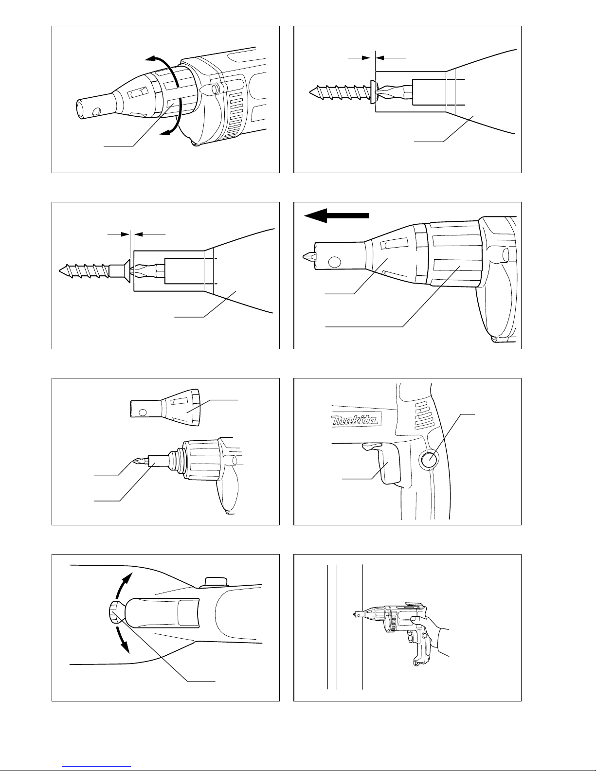
1 Borghuls
2 Ongeveer 1 mm
3 Locator
4Bit
5 Magnetische bithouder
6 Trekschakelaar
7 Vergrendelknop
8 Omkeerschakelaar
9Haak
TECHNISCHE GEGEVENS
Model 6823 6824 6825 / 6825R
Capaciteiten
Zelfborende schroef .................................................................6mm 6mm —
Gipsplaatschroef ......................................................................6mm 5mm 4mm
Toerental onbelast (min–1) ...........................................................0 – 2500 0 – 4500 0 – 6000
Totale lengte ................................................................................301mm 290mm 290mm
Netto gewicht ...............................................................................1,5kg 1,4kg 1,4kg
• In verband met ononderbroken research en ontwikke-
ling behouden wij ons het recht voor bovenstaande
technische gegevens te wijzigen zonder voorafgaande
kennisgeving.
• Opmerking: De technische gegevens kunnen van land
tot land verschillen.
Doeleinden van gebruik
Dit gereedschap is bedoeld voor het indraaien van
schroeven in hout, metaal en kunststof.
Stroomvoorziening
De machine mag alleen worden aangesloten op een
stroombron van hetzelfde voltage als aangegeven op de
naamplaat, en kan alleen op enkel-fase wisselstroom
worden gebruikt. De machine is dubbel-geïsoleerd vol-
gens de Europese standaard en kan derhalve ook op
een niet-geaard stopkontakt worden aangesloten.
Veiligheidswenken
Voor uw veiligheid dient u de bijgevoegde Veiligheids-
voorschriften nauwkeurig op te volgen.
AANVULLENDE
VEILIGHEIDSVOORSCHRIFTEN
1. Zorg altijd dat u stevig op uw voeten staat.
Zorg dat wanneer u op hooggelegen plaatsen
werkt, niemand onder u staat.
2. Houd het gereedschap stevig vast.
3. Houd uw handen uit de buurt van de draaiende
delen.
4. Bij schroeven in muren, vloeren en dergelijke
bestaat het gevaar dat u onder spanning staande
elektrische kabels tegenkomt. RAAK DERHALVE
DE METALEN DELEN VAN HET GEREEDSCHAP
NIET AAN!
Houd het gereedschap uitsluitend vast bij de
geïsoleerde handgreep ter vermijding van elek-
trische schok in het geval dat het gereedschap
in aanraking komt met een onder spanning
staande kabel.
5. Raak onmiddellijk na het inschroeven de bit niet
aan, aangezien deze ontzettend heet kan zijn en
brandwonden kan veroorzaken.
BEWAAR DEZE VOORSCHRIFTEN.
BEDIENINGSVOORSCHRIFTEN
Instellen van de diepte
De diepte kan worden ingesteld door de borghuls te
draaien. Draai deze in de “A” richting voor minder diepte
en in de “B” richting voor meer diepte. Een volle slag van
de borghuls komt overeen met een 1,5mm verandering
in diepte. (Fig. 1)
Stel de borghuls zo in dat de afstand tussen het uiteinde
van de locator en de schroefkop ongeveer 1mm
bedraagt, zoals afgebeeld in Fig. 2 of 3. Maak een proef
door een schroef in uw materiaal of in een gelijksoortig
materiaal te draaien. Indien de diepte niet juist is voor de
betreffende schroef, dient u verder af te stellen totdat de
juiste diepte-instelling is verkregen. (Fig. 2 en 3)
Verwijderen of installeren van de bit (Fig. 4 en 5)
Belangrijk:
Zorg altijd ervoor dat het gereedschap is uitgeschakeld
en de stekker uit het stopcontact is verwijderd, alvorens
de bit te verwijderen of te installeren.
Om de bit te verwijderen, trekt u eerst de locator uit de
borghuls. Houd daarna de bit met een tang vast en trek
hem uit de magnetische bithouder. Het uittrekken is
soms gemakkelijker wanneer u de bit met de tang wat
heen en weer beweegt.
Om de bit te installeren, drukt u deze stevig in de magne-
tische bithouder. Installeer vervolgens de locator door
deze stevig op de borghuls te drukken.
Bediening van de trekschakelaar (Fig. 6)
LET OP:
Alvorens de stekker in een stopcontact te steken, dient u
altijd te controleren of de trekschakelaar naar behoren
werkt en bij loslaten onmiddellijk naar de “OFF” positie
terugkeert.
Om de machine te starten, de trekschakelaar gewoon
indrukken. Het toerental vermeerdert naarmate de scha-
kelaar harder wordt ingedrukt. Laat de schakelaar los om
de machine te stoppen. Voor continu gebruik, de trek-
schakelaar indrukken en dan de vergrendelknop indruk-
ken. Om de machine vanuit deze vastzetpositie te
stoppen, de trekschakelaar volledig indrukken en deze
dan loslaten.
OPMERKING:
Zelfs wanneer u de trekschakelaar indrukt en de motor
draait, zal de bit niet draaien voor u de punt van de bit op
de schroefkop plaatst en voorwaartse druk uitoefent om
de koppeling in te schakelen.

13
Bediening van de omkeerschakelaar (Fig. 7)
LET OP:
• Controleer altijd de draairichting alvorens de machine
te gebruiken.
• Gebruik de omkeerschakelaar alleen nadat de machine
volledig tot stilstand is gekomen. Indien u de draairich-
ting verandert voordat de machine is gestopt, kan de
machine beschadiging oplopen.
Deze machine is voorzien van een omkeerschakelaar
voor het veranderen van de draairichting. Zet de omkeer-
schakelaarknop naar de “A” zijde voor linkse draairich-
ting of naar de “B” zijde voor rechtse draairichting.
Bediening
Plaats de schroef op de punt van de bit en plaats de punt
van de schroef op het te bevestigen werkstuk. Oefen
druk uit op de machine en start deze. Trek de machine
terug zodra de koppeling ingrijpt. Laat daarna de trek-
schakelaar los.
LET OP:
• Wanneer u de schroef op de punt van de bit aanbrengt,
moet u ervoor zorgen dat u de schroef niet naar binnen
drukt. Als de schroef naar binnen wordt gedrukt, kan
de koppeling worden ingeschakeld zodat de schroef
plotseling begint te draaien. Dit kan beschadiging van
het werkstuk of verwonding veroorzaken.
• Zorg ervoor dat de bit recht in de schroefkop zit, aange-
zien de schroef en/of bit anders beschadigd kunnen
raken.
Haak (Fig. 9 en 10)
De haak is handig om het gereedschap tijdelijk op te
hangen. Om de haak te gebruiken, trekt u deze naar bui-
ten in de “A” richting en dan duwt u deze in de “B” rich-
ting om hem vast te zetten.
Wanneer u de haak niet gebruikt, volgt u de boven-
staande procedure in omgekeerde volgorde om de haak
naar zijn oorspronkelijke positie terug te brengen.
Procedure voor het installeren en verwijderen
van de verwijderbare kabeladapter
Belangrijk:
Zorg dat het gereedschap is uitgeschakeld en niet op het
stopcontact is aangesloten alvorens de verwijderbare
kabeladapter te installeren of te verwijderen.
Installeren
Steek de verwijderbare kabeladapter zo ver mogelijk erin
zodat het teken op het voedingskabeleinde van de
kabel adapter overeenkomt met het teken op het
andere einde (aansluitgedeelte op het gereedschap).
(Fig. 11)
Draai de verwijderbare kabeladapter naar rechts totdat
hij met de vergrendelknop is vergrendeld. (Fig. 12)
Wanneer de kabeladapter vergrendeld is, komt het
teken op het voedingskabeleinde van de kabeladap-
ter overeen met het teken op het andere einde (aan-
sluitgedeelte op het gereedschap).
(Fig. 13)
Verwijderen
Houd het onderste gedeelte van de vergrendelknop inge-
drukt en draai de verwijderbare kabeladapter naar links
totdat hij stopt. (Fig. 14)
Trek daarna de verwijderbare kabeladapter eruit.
(Fig. 15)
ONDERHOUD
LET OP:
Zorg er altijd voor dat de machine is uitgeschakeld en de
stekker uit het stopcontact is verwijderd alvorens onder-
houd aan de machine uit te voeren.
Opdat het gereedschap veilig en betrouwbaar blijft, die-
nen alle reparaties, onderhoud of afstellingen te worden
uitgevoerd bij een erkend Makita service centrum.
ACCESSOIRES
LET OP:
• Deze accessoires of hulpstukken worden aanbevolen
voor gebruik met het Makita gereedschap dat in deze
gebruiksaanwijzing wordt beschreven. Het gebruik van
andere accessoires of hulpstukken kan gevaar voor
persoonlijke verwonding opleveren. Gebruik de acces-
soires of hulpstukken uitsluitend voor het gespecifi-
ceerde doel.
Wenst u meer informatie over deze accessoires, neem
dan contact op met het dichtstbijzijnde Makita service-
centrum.
• Phillips insteekbit 1-25, 2-25 en 3-25
• Magnetische bithouder 6,35-76 en 6,35-60
Other manuals for 6823
9
This manual suits for next models
3
Table of contents
Languages:
Other Makita Power Screwdriver manuals

Makita
Makita 6827 User manual

Makita
Makita XAD02 User manual

Makita
Makita DFS451RMJ User manual

Makita
Makita DFL083F User manual

Makita
Makita 6826 User manual

Makita
Makita DFT046F User manual

Makita
Makita DFT087F User manual

Makita
Makita BFR550 User manual

Makita
Makita FS4300A User manual

Makita
Makita BFT080F User manual

Makita
Makita DFR540 User manual

Makita
Makita FS2700 User manual

Makita
Makita DFS451 User manual

Makita
Makita 6805BV User manual

Makita
Makita DFL651F User manual

Makita
Makita BFL201F User manual

Makita
Makita BFL061F User manual

Makita
Makita BFR540 User manual

Makita
Makita BFR540 User manual

Makita
Makita BFL300F User manual