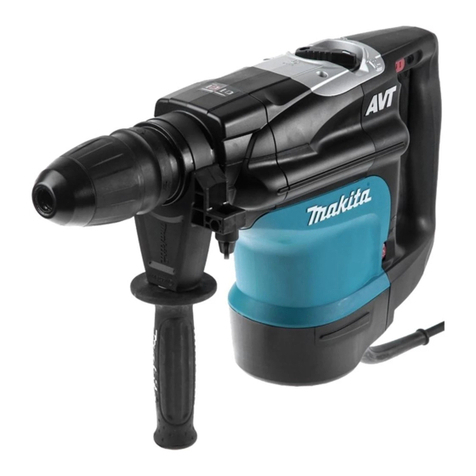
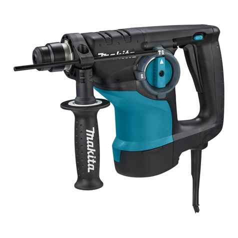
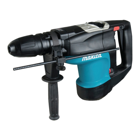
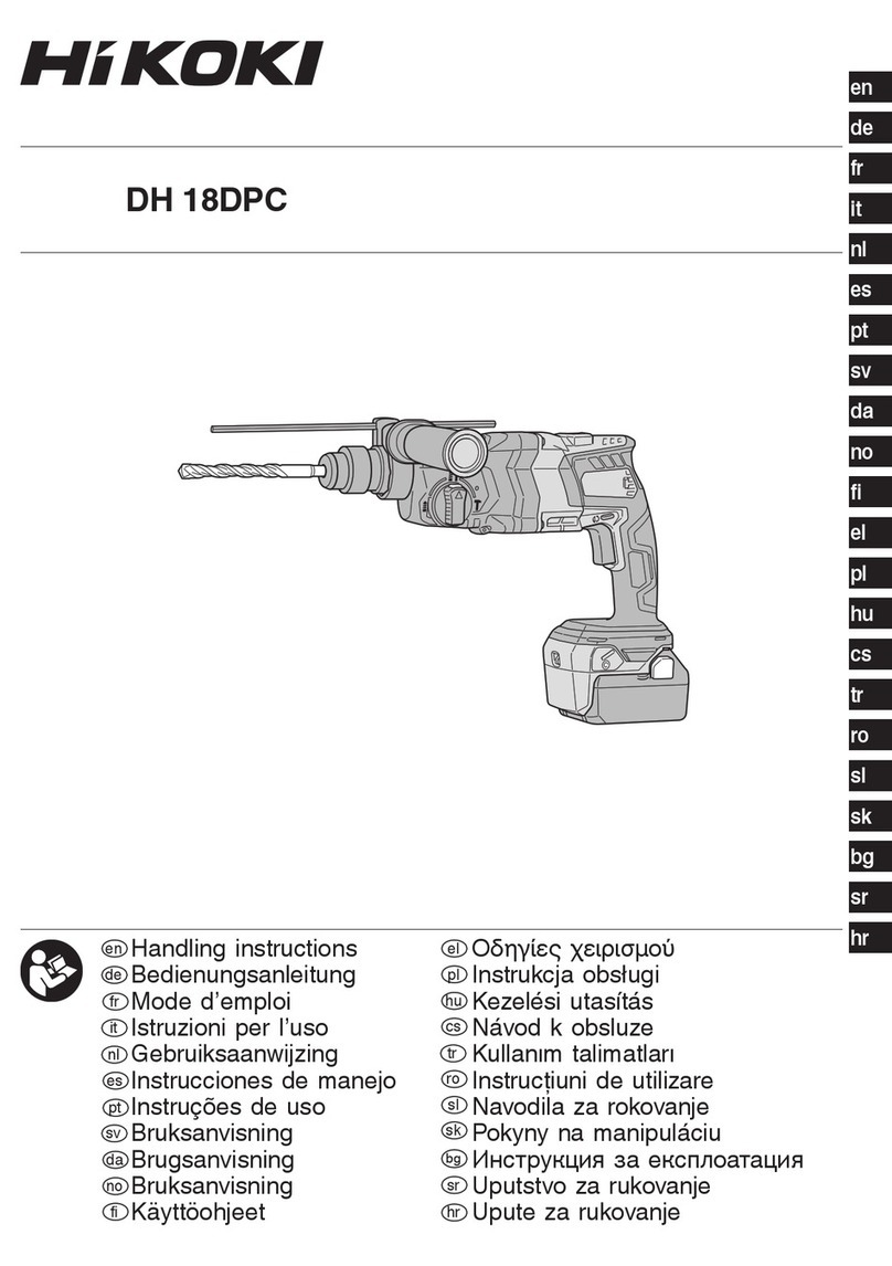
Makita HR3851 User manual

Rotarv
Hammer
Capacities
Tungsten-carbide bit Core bit
118
mm
(4-518”)
38
mm
(1-1/2”)
~
I
38
mm
(1-1/2”)
MODEL
HR3851
Overall Net weight
No
load speed Blows per
(RPMI
minute
445
mm
7.5
kg
2r900
(17-112”)
(16.5
Ibs)
240
INSTRUCTION MANUAL
*
Note: Specifications may differ from country
to
country.

IMPORTANT
SAFETY INSTRUCTIONS
(For
All
Tools)
WARNING:
WHEN USING ELECTRICTOOLS, BASICSAFETY
PRECAUTIONS SHOULDALWAYS BE FOLLOWEDTO REDUCE
THE RISK OF FIRE, ELECTRIC SHOCK, AND PERSONAL
INJURY, INCLUDING THE FOLLOWING:
READ ALL INSTRUCTIONS.
1.
2.
3.
4.
5.
6.
7.
8.
9.
10.
11.
12.
13.
2
KEEP WORK AREA CLEAN. Cluttered areas and benches invite injuries.
CONSIDER WORK AREA ENVIRONMENT. Don’t use power tools in damp
or wet locations. Keep work area well
lit.
Don‘t expose power tools torain.
Don’t use tool in presence of flammable liquids or gases.
KEEP CHILDREN AWAY.
All
visitors should be kept away from work area.
Don’t let visitors contact tool or extension cord.
STORE IDLETOOLS. When not
in
use, tools shouldbe stored
in
dry, and
high
or locked-up place
-
out of reach of children.
DON’T FORCE TOOL.
It
willdothejob better andsaferatthe ratefor which
it
was intended.
USE RIGHT TOOL. Don’t force small tool
or
attachment to do the job of a
heavy-duty tool. Don’t use tool for purpose not intended.
DRESS PROPERLY. Don’t wear loose clothing
or
jewelry. Theycanbecaught
in moving parts. Rubber gloves and non-skid footwear are recommended
when working outdoors. Wear protective hair coveringtocontain long hair.
USE SAFETY GLASSES.
Also
use face or dust mask if cutting operation is
dusty.
DON’T ABUSE CORD. Never carrytool by cord or yank
it
todisconnect from
receptacle. Keep cord from heat, oil, and sharp edges.
SECURE WORK. Use clamps or a vise to hold work. It’s safer than using
your hand and
it
frees both hands to operate tool.
DON’T OVERREACH. Keep proper footing and balance at all times.
MAINTAIN TOOLS WITH CARE. Keep tools sharp and clean for better and
safer performance. Follow instructions for lubricatingand changing acces-
sories. Inspecttoolcordsperiodically and
if
damaged, haverepairedby autho-
rized service facility. Inspect extension cords periodically and replace
if
damaged. Keep handles dry, clean, and free from oil and grease.
DISCONNECTTOOLS. When not inuse, before servicing, and when chang-
ing accessories, such as blades, bits, cutters.

14.
REMOVE
ADJUSTING
KEYS
AND
WRENCHES.
Form habit of checking to
see that keysand adjusting wrenches are removed fromtool before turning
it
on.
15.
AVOID UNINTENTIONALSTARTING. Don’t carry plugged-in tool withfinger
on switch. Be sure switch is
OFF
when plugging
in.
16.
OUTDOOR USE EXTENSIONCORDS. Whentool is usedoutdoors, use only
extension cords intended for use outdoors and
so
marked.
17.
STAY ALERT. Watch what you are doing, usecommonsense. Don’t operate
tool when you are tired.
18.
CHECK DAMAGED PARTS. Beforefurther use of
the
tool, a guard or other
part that
is
damaged should be carefully checked to determine that
it
will
operate properly and perform itsintended function. Check for alignment of
moving parts, binding of moving parts, breakage of parts, mounting, and
any other conditions that may affect its operation. A guard or other part
that is damaged should be properly repaired or replaced by an authorized
service center unless otherwise indicated elsewhere in this instruction
manual. Havedefective switches replacedbyauthorized servicecenter. Don’t
use tool if switch does not turn
it
on and off.
19.
GUARD AGAINST ELECTRIC SHOCK. Preventbody contact
with
grounded
surfaces. For example; pipes, radiators, ranges, refrigerator enclosures.
20.
PROPER GROUNDING.This tool should be grounded while inusetoprotect
the operator from electric shock.
21.
EXTENSIONCORDS: Use only three-wireextension cords which havethree-
prong grounding-type plugs and three-pole receptacles which accept the
tool’s plug. Replace or repair damaged or worn cord immediately.
VOLTAGE WARNING: Before connecting the tool to a power source (receptacle,
outlet, etc.) be sure the voltage supplied is the same as that specified on the
nameplate of the tool. A power source with voltage greater than that specified
for the tool can result in SERIOUS INJURYto the user
-
as well as damage to
the tool.
If
in doubt, DO NOT PLUG IN THE TOOL. Using a power source with
voltage less than the nameplate rating is harmful to the motor.
3

GROUNDING INSTRUCTIONS
ALL
GROUNDED, CORD-CONNECTEDTOOLS:
In
the event of a malfunction or
breakdown, grounding provides a pathof least resistance for electric current to
reducethe risk of electric shock. This toolisequippedwithan electric cordhaving
an equipment-grounding conductor and a grounding plug. The plug must be
pluggedinto a matching outlet that is properly installed and grounded
in
accor-
dance with all local codes and ordinances.
Do
not modify the plug provided-if
it
will
not fit the outlet, have the proper
outlet installed by a qualified electrician.
Improperconnection of the equipment-grounding conductor can result
in
a risk
of electric shock. The conductor with insulation having an outer surface that
is green
with
or without yellow stripes is the equipment-grounding conductor.
If
repair or replacement of the electric cord or plugis necessary, do notconnect
the equipment-grounding conductor to a live terminal.
Check with a qualified electrician or serviceman if the grounding instructions
are not completely understood, or if
in
doubt as to whether the tool is properly
grounded.
This tool is intended for use on a circuit that has an outlet that looks like the
one illustratedinFigure
A.
The toolhas a grounding plugthat looks like the plug
illustrated in Figure
A.
A
temporary adapter, which looks like the adapter illus-
tratedinFigure
B
and C, may beusedtoconnect this plugtoa 2-pole receptacle
as shown
in
Figure
B
if
a properly grounded outlet isnot available.The temporary
adapter should be used only
until
a properly grounded outlet can be installed
by a qualified electrician. The green-colored rigid ear, lug, etc. extending from
the adapter must be connected toa permanentgroundsuchas a properly ground-
ed outlet box.
FIG.
A
GROUNDING METHODS
FIG.
0
/
Outlet
BOX
-L
-
FIG.
C
Adapter
9
GroundingPin Grounding
Means
4

ADDITIONAL SAFETY RULES
1.
Wear a hard hat (safety helmet), safety glasses andlor face shield.
It
is also
highly recommended that
you
wear a dust mask,
ear
protectors
and
thickly
padded gloves.
2.
Be sure the bit is secured in place before operation.
3.
Under normaloperation, the
tool
isdesigned toproducevibration. The screws
can come loose easily, causing
a
breakdown or accident. Check tightness
of screws carefully before operation.
4.
Incold weather or when the tool has not been usedfor a long time, letthe
tool warm up for several minutes by operating
it
under no load.
This
will
loosen up the lubrication. Without proper warm-up, hammering operation
is difficult.
Be sure
no
one is below when using the tool
in
high locations.
5.
Always be sure you have a firm footing.
6.
Hold the tool firmly with both hands.
7.
Keep hands away from moving parts.
8.
Do
not leave the tool running. Operate the tool only when hand-held.
9.
Do
not point the tool at any one
in
the area when operating. The bit could
fly out and injure someone seriously.
IO.
When drilling or chippingintowalls, floors or wherever "live" electrical wires
may be encountered,
DO
NOT TOUCH ANY
METAL
PARTS
OF
THE TOOL!
Hold the tool by the insulated grasping surfaces to prevent electric shock
if you drill or chip into a "live" wire.
11.
Do
not touch the bit or parts close to the bit immediately after operation;
they may be extremely hot and could burn your skin.
SAVE THESE INSTRUCTIONS.
5

Side grip (auxiliaryhandle)
For maximum control and safer operation,
always use the side grip with this tool. The
side grip swings around to either side,
allowing easy handling of the tool in any
position. Loosen the side grip by turning
it
counterclockwise, swing
it
tothe desired
position and then tighten
it
by turning
clockwise.
The side grip can also be installed in the
position shown in the figure. Remove the
side grip from the grip base by turning the
side grip counterclockwise. Screw the side
grip on either side
of
the tool, whichever
is
convenient.
Installingor removing drill bit or other bits (bull point, etc)
CAUTION
:
Always be sure that the tool
is
switched off and unplugged before installing or removing
the bit.
Press in the tool retainer and turn
it
until
the red dots on the
tool
retainer and the
6

Insert the bit intothe tool holder
as
far
as
it
will go. Press in the tool retainer and
turn
it
a
full
180
degrees. Then release
it
to
secure the bit.
To
removethe bit, follow the installation procedures in reverse.
Adjusting depth of drilling
Loosen the wing bolt and adjust the depth
gauge to the desired depth. After adjusting,
tighten the wing bolt.
Selecting action mode
Rotationwithhammering
:
For drilling inconcrete,masonry
etc.,
rotate
the change lever tothe
?@
position.
Hammeringonly
:
For chipping, scaling or demolition opera-
tions, rotate the change lever tothe posi-
tion.
I1
!?
n
Chanqe lever
1
For
rotation
3
CAUTION
:
.Do
not rotate the change lever when the tool
is
running under load. The tool will be
damaged.
.To
avoid rapid wear on the mode change mechanism, be sure that the change lever
is
always positively located in one
of
the two action mode positions.

Switch action
To
start
the tool, simply pull the trigger
Release
the trigger tostop.
I
Triqqer
switch
I
CAUTION
:
0
Before plugging in the tool, always check to
see
that the trigger switch actuates properly
0
Do
nottape,
tie
or otherwisesecurethe trigger in the "ON" position.
and returns tothe
"OFF"
position when released.
Chipping. Scaling
-
Demolition
Hold the tool firmly with both hands. Turn
the tool on and apply slight pressure on
the tool
so
that the tool will not bounce
around, uncontrolled. Pressing very hard
onthe tool will not increasethe efficiency.
Hammer drilling operation
Position the bit
at
the location for the
hole, then pullthe trigger.
Do
not force the tool. Light pressuregives
best results. Keep the tool in position and
prevent
it
from slipping away from the
hole.
Do
not apply more pressure when the hole
becomes clogged with chips or particles.
Instead, run the tool
at
an idle, then re-
move from the hole. By repeating this
several times, the holewill be cleaned out.
CAUTION
:
When the bit begins to break through concrete or if the bit strikes reinforcing rods em-
bedded in concrete, the tool may react dangerously. Maintain good balanceand safe foot-
ingwhile holding the tool firmly with both handsto preventdangerous reaction.
8

BlOw-oUt
bulb
Use the blow-out bulb to clean out the
hole.
Core
bit
(optional
accessory)
[When usingthe center bit]
Screw the core bit on the adapter. Install
the adapter with the core bit inthe tool in
the same manner
as
a
drill bit.
Install the center bit.
Rest
the core bit
on
the concreteand turn
the tool on. Once the core bit has cut
a
shallow groove into the concrete, remove
the center bit. Then resumedrilling.
9

To removethe core bit, follow the procedures
(1
)
or
(2).
1)
Rotate the change lever to the posi-
tion. Then rest the core biton the con-
crete and turn the tool on. The core bit
will come loose from the hammering
action.
2)
Hold thi 7ter with the wrench, in-
sert the rod intothe hole inthe core bit
and tap with
a
hammer to unscrew.
[Whennot using the center bit]
Screw the core bit on the adapter. Install
the adapter with the core bit in the tool in
the same manner
as
a
drill bit.
Rotate the change lever to the position.
Rest
the core bit on the concreteand turn
the tool on. Once the core bit has cut
a
shallow groove into the concrete, rotate
the change lever to the
f(B
position and
resumedrilling.
NOTE
:
No problem
is
caused even if the core bitunscrewsslightly during brief use since the core
bitrotates inthe tightening direction.
To remove the core bit, follow the same removal procedures covered in [whenusingthe
center bit].
10

MAINTENANCE
CAUTION
:
Always be sure that the tool
is
switched off and unplugged before attempting to perform
inspection or maintenance.
Replacing carbon brushes
When the resin insulating tip inside the
carbon brush
is
exposed to contact the
commutator,
it
will automatically shut off
the motor.
When this occurs, both carbon brushes
should be replaced
at
the same time. Use
only identical carbon brushes.
,
Insulating
tip
>
Carbon brush
1'
Use
a
screwdriver to remove the brush
holder caps. Take out the worn carbon
brushes, insert the new ones and secure the
Screwdriver
11

Lubrication
Lubricatethe tool every time the carbon brushesare replaced.
Runthe tool for several minutes towarm
it
up, then rest the toolonthe table with the
bit end pointing upwards. This will allow
the old grease to collect inside the crank
housing. After five minutes, take off the
crank cap and remove the old grease. Wipe
out
all
grease inside and replace with
a
fresh supply
(30
g;
1
02).
CAUTION
:
0
Filling with more than the specified
amount
of
grease (approx.
30
g;
1
02.)
can
cause faulty hammering, action or tool
failure. Fill only with the specified
amount of grease.
The use of any other grease may harm the
tool.
0
Use only Makita genuinegrease.
Sharpening tungsten-carbidetip bit
When your bit becomes dull, use an ordinary bench grinder with
a
wheel made of silicon
carbidetoresharpen
it.
CAUTION
:
.Be sure to maintain the original angles
of
the tip. Especiallywithout
60'
chamfering,
0
Do
notquench the bit in water or
oil.
0
Do
not grind the sides Band C.
the tungsten-carbidetipmay be damaged.
130"
0.53r
A
-
A'
Cross
section
To maintain product SAFETY and RELIABILITY, repairs, any other maintenance or
adjustment should be performed by Makita Authorized or Factory Service Centers,
always using Makita replacement parts.
12

ACCESSOR
I
ES
CAUTION
:
These accessories or attachments are recommended for use with your Makita
tool
specified
in
this
manual. The use
of
any other accessories
or
attachmentsmight present a risk
of
injurytopersons. The
accessories orattachmentsshould be used only
in
the proper and intended manner.
*Spline shank carbide bit Bull point
300
mm
(11-7/8")
Part
No.
798146-1
450
mm
(17-3/4")
Part
No.
798147-9
*
P.
C.
0.
bit
(For termite treatment and deep
holes.)
Cold chisel
26
mm
(1")
x
300
mm
(1
1-7/8')
Part
No.
798139-8
26
mm
(I")
x
450
mm
(17-3/4")
Part
No.
798140-3
Scaling
chisel
50
mm
(2")
x
300
mm
(1
1-7/8")
Part
No.
798141-1
Groovingchisel
22
mm
(55/64")
x
300
mm
(1
1-7/8")
Part
No.
798142-9
26
mm
(1")
x
300
mm
(1
1-7/8')
Part
No.
798143-7
A-Taper adapter
Part
No.
798135-6
Groundrodadapter
20
mm
(3/4")
x
170
mm
(6-1
1
/16")
Part
No.
798132-2
13

0
Carbide tipped core bit
0
Core bit adapter set
Part
No.
798138-0
[includes
center
point
(Part
No.
752027-3)
&
rod
(Part
No.
256815-5)l
0
Drift pin
Part
No.
765010-1
1
0
Hammer grease
Part
No.
181490-7
Blow-Outbulb
Part
No.
765009-6
0
Hex wrench
5
Part
No.
783203-8
0
Depth gauge
Part
No.
321248-4
0
Hex
wrench
4
Part
No.
783202-0
0
Steel carrying case
Part
No.
181876-5
0
Lock nut wrench
35
Part
No.
782407-9
14

Drc
16-
91
US
38
mm
(1-1/2")
ROTARY
HAMMER
Model
HR3851
Note: The switch and other part configurations
may differ from country to country.
15

MAKVA
LIMITED
ONE
YEARWARRANTY
Warranty
Policy
Every Makita
tool
is thoroughly inspected and tested before leaving the factory. It
IS
warranted to
be
free
of
defects from workmanship and materials
for
the period
of
ONE YEAR from the date
of
original purchase. Should any trouble develop dunngthis
one-year
period, return the COMPLETE
tool, freight prepaid, to
one
of
Maklta's Factory
or
Authorized Service Centers.
If
inspeetion
shows
the trouble is caused by defective workmanship
01
material,
Maktta will repair
(or
at
our optlon,
replace) without charge.
This Warranty does not apply where:
repars
have
been made
or
attempted by others:
repairs
are
required because
of
normal
wear and tear
The tool has been
abused,
misused
or
improperly mamtamed
,
alterations have
been
made
to
the
tool.
IN NO EVt.NT SHALL MAKITA BE LIABLE
FOR
ANY INDIRECT, INCIDENTAL
OR
CON-
SEQUENTIAL DAMAGES FROM THE SALE
OR
USE
OF
THE PRODUCT. THIS DISCLAIMER
APPLIESBOTH DURING AND AFTER THE TERM OF THIS WARRANTY.
..~
~
i
MAKITA DISCLAIMS LIABILITY FOR ANY IMPLIED WARRANTILS, INCLUDING IMPLIED
WARRANTIES
OF
"MERCHANTABILITY" AND "FITNESS FOR A SPLClFlC PURFQSI-."
AFTER THE ONE-YEAR TERM
OF
THIS WARRANTY.
This Warranty
glves
you specific legal rights. and
you
may
also
have other rights which vary from
state
to
state. Some states do
not
allow
the
exclusion
or
limitation
of
Incidental
or
consequential
damages,
EO
the above limitation
or
exclusion may
not
apply to you. Some states do
not
allow
limitation
on
how long
an
implied warranty lasts.
so
the above hmltation may
not
apply
to
you.
Makita Corporation
3-11
-8,
Sumiyoshi-cho,
Anjo, Aichi
446
Japan
PRINTED IN JAPAN
1992
-
2
-
N
8834818063
Other manuals for HR3851
3
Table of contents
Other Makita Rotary Hammer manuals

Makita
Makita DHR171RAJ User manual

Makita
Makita HR3200C User manual

Makita
Makita HR1830 User manual

Makita
Makita HR2800 User manual

Makita
Makita CP100DSA User manual

Makita
Makita HR4000C Quick start guide

Makita
Makita HR4501C User manual

Makita
Makita HR5000 User manual

Makita
Makita HR5000 Quick start guide

Makita
Makita HR3540C User manual

Makita
Makita HR166DWMX1 User manual

Makita
Makita HR3200C User manual

Makita
Makita HR140D User manual

Makita
Makita HR2470 User manual
Makita
Makita HR3550C User manual

Makita
Makita HR2300 User manual

Makita
Makita HR2300 User manual

Makita
Makita HR3200C User manual

Makita
Makita HR1830F User manual

Makita
Makita M8700 User manual