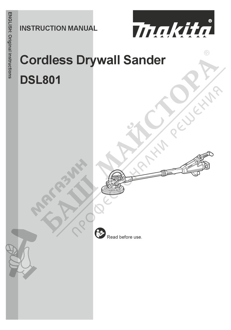
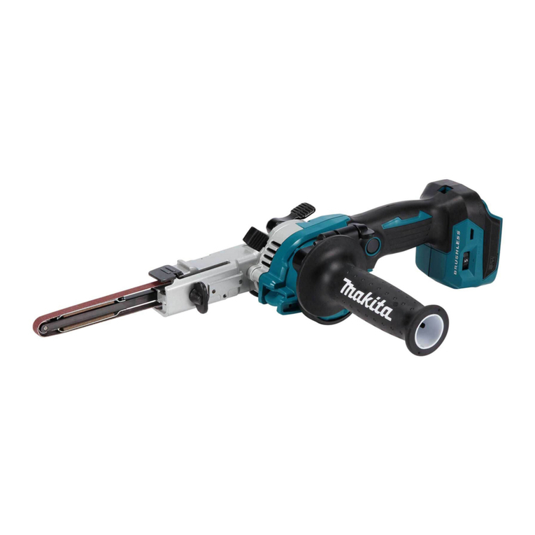
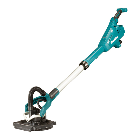
Makita DSL800 User manual

DSL800
EN Cordless Drywall Sander INSTRUCTION MANUAL 9
FR Ponceuse murale à batterie MANUEL D’INSTRUCTIONS 19
DE Akku-Langhalsschleifer BETRIEBSANLEITUNG 30
IT Levigatrice per cartongesso a
batteria ISTRUZIONI PER L’USO 42
NL Accugipsplaatschuurmachine GEBRUIKSAANWIJZING 54
ES Lijadora Inalámbrica para
Tablaroca
MANUAL DE
INSTRUCCIONES 66
PT Lixadeira de Parede a Bateria MANUAL DE INSTRUÇÕES 78
DA Akku sandslibemaskine til
gipsplader BRUGSANVISNING 89
EL
100
TR
KULLANMA KILAVUZU 112

12
3
Fig.1
1
2
Fig.2
1
AB
Fig.3
1
2
3
Fig.4
1
Fig.5
1
Fig.6
Fig.7
1
Fig.8
2

1
2
Fig.9
1
2
Fig.10
21
Fig.11
12
Fig.12
1
2
Fig.13
1
Fig.14
3

1
2
3
Fig.15
1 2
3
Fig.16
1
2
3
4
Fig.17
Fig.18
4

1
Fig.19
1
2
Fig.20
12
Fig.21
Fig.22
Fig.23
Fig.24
5

1
Fig.25
1
2
3
4
Fig.26
1
2
3
Fig.27
1
Fig.28
12
21
Fig.29
Fig.30
6

1
Fig.31
21
Fig.32
1
Fig.33
1
Fig.34
12
21
Fig.35
12
Fig.36
7

132
Fig.37
8

9 ENGLISH
ENGLISH (Original instructions)
SPECIFICATIONS
Model: DSL800
Paper size 225 mm
Pad diameter 210 mm
Rated speed (n) 1,000 - 1,800 min-1
Dimensions 1,100 mm - 1,520 mm x 259 mm x 273 mm
Rated voltage D.C. 18 V
Net weight 4.5 - 5.7 kg
without notice.
-
Applicable battery cartridge and charger
Charger
residence.
WARNING: Only use the battery cartridges and chargers listed above.
Intended use
Noise
-
Sound pressure level (L
NOTE:
measured in accordance with a standard test method
NOTE:
WARNING: Wear ear protection.
WARNING: The noise emission during actual
use of the power tool can differ from the declared
value(s) depending on the ways in which the
tool is used especially what kind of workpiece is
processed.
WARNING: Be sure to identify safety mea-
sures to protect the operator that are based on an
estimation of exposure in the actual conditions of
use (taking account of all parts of the operating
cycle such as the times when the tool is switched
off and when it is running idle in addition to the
trigger time).
Vibration
-
h, DS2or less
2
NOTE:
measured in accordance with a standard test method
NOTE:
WARNING:
The vibration emission during actual
use of the power tool can differ from the declared val-
ue(s) depending on the ways in which the tool is used
especially what kind of workpiece is processed.
WARNING: Be sure to identify safety mea-
sures to protect the operator that are based on an
estimation of exposure in the actual conditions of
use (taking account of all parts of the operating
cycle such as the times when the tool is switched
off and when it is running idle in addition to the
trigger time).
EC Declaration of Conformity
For European countries only
to this instruction manual.

10 ENGLISH
SAFETY WARNINGS
General power tool safety warnings
WARNING: Read all safety warnings, instruc-
with this power tool.
Save all warnings and instruc-
tions for future reference.
(cordless) power tool.
Cordless drywall sander safety warnings
Safety Warnings Common for Sanding Operations:
1.
This power tool is intended to function as a sander.
Read all safety warnings, instructions, illustrations
2.
Operations such as grinding, wire brushing,
polishing or cutting-off are not recommended
to be performed with this power tool. Operations
3.
designed and recommended by the tool manufac-
turer.
4. The rated speed of the accessory must be at
least equal to the maximum speed marked on
the power tool.
5. The outside diameter and the thickness of your
accessory must be within the capacity rating
of your power tool.
Do not use a damaged accessory. Before each
use inspect the accessory such as pad for cracks,
tear or excess wear. If power tool or accessory is
dropped, inspect for damage or install an undam-
aged accessory. After inspecting and installing
an accessory, position yourself and bystanders
away from the plane of the rotating accessory and
run the power tool at maximum no-load speed
for one minute.
7. Wear personal protective equipment.
Depending on application, use face shield,
safety goggles or safety glasses. As appro-
priate, wear dust mask, hearing protectors,
gloves and workshop apron capable of stop-
ping small abrasive or workpiece fragments.
cause hearing loss.
8.
Keep bystanders a safe distance away from work
area. Anyone entering the work area must wear
personal protective equipment.
9. Position the cord clear of the spinning acces-
sory.
10. Never lay the power tool down until the acces-
sory has come to a complete stop. The spinning
11. Do not run the power tool while carrying it at
your side.
12.
materials. Sparks could ignite these materials.
13. Do not use accessories that require liquid
coolants.
Kickback and Related Warnings
-
-
workpiece, the edge of the pad that is entering into the
pinch point can dig into the surface of the material caus-
1.
your body and arm to allow you to resist kickback
forces. Always use auxiliary handle, if provided, for
maximum control over kickback or torque reaction
during start-up.-
2. Never place your hand near the rotating acces-
sory.
3. Do not position your body in the area where
power tool will move if kickback occurs.
4. Use special care when working corners, sharp
edges etc. Avoid bouncing and snagging the
accessory.
5. Do not attach a saw chain woodcarving blade
or toothed saw blade.-
1. Do not use excessively oversized sanding
disc paper. Follow manufacturers recommen-
dations, when selecting sanding paper. Larger
11 ENGLISH
Additional Safety Warnings:
1. Do not leave the tool running. Operate the tool
only when hand-held.
2. Check that the workpiece is properly
supported.
3. Pay attention that the pad continues to rotate
after the tool is switched off.
4. If working place is extremely hot and humid,
or badly polluted by conductive dust, use a
short-circuit breaker (30 mA) to assure opera-
tor safety.
5. Do not use the tool on any materials contain-
ing asbestos.
Do not use cloth work gloves during operation.
7. Always work in well ventilated area.
8.
stable surface.
9. When operating the tool, connect the tool to a
vacuum cleaner as much as possible to keep
the working area clean and prevent the oper-
ator from inhaling particles generated by the
operation.
SAVE THESE INSTRUCTIONS.
WARNING: DO NOT let comfort or familiarity
with product (gained from repeated use) replace
strict adherence to safety rules for the subject
product. MISUSE or failure to follow the safety
rules stated in this instruction manual may cause
serious personal injury.
Important safety instructions for
battery cartridge
1. Before using battery cartridge, read all instruc-
tions and cautionary markings on (1) battery
charger, (2) battery, and (3) product using
battery.
2. Do not disassemble battery cartridge.
3. If operating time has become excessively
shorter, stop operating immediately. It may
result in a risk of overheating, possible burns
and even an explosion.
4. If electrolyte gets into your eyes, rinse them
out with clear water and seek medical atten-
tion right away. It may result in loss of your
eyesight.
5. Do not short the battery cartridge:
(1) Do not touch the terminals with any con-
ductive material.
(2) Avoid storing battery cartridge in a con-
tainer with other metal objects such as
nails, coins, etc.
(3) Do not expose battery cartridge to water
or rain.
A battery short can cause a large current
breakdown.
Do not store the tool and battery cartridge in
locations where the temperature may reach or
exceed 50 °C (122 °F).
7. Do not incinerate the battery cartridge even if
it is severely damaged or is completely worn
8. Be careful not to drop or strike battery.
9. Do not use a damaged battery.
10.
The contained lithium-ion batteries are subject to
the Dangerous Goods Legislation requirements.
-
-
national regulations.
Tape or mask off open contacts and pack up the
around in the packaging.
11. Follow your local regulations relating to dis-
posal of battery.
12. Use the batteries only with the products
-
SAVE THESE INSTRUCTIONS.
CAUTION: Only use genuine Makita batteries.
charger.
Tips for maintaining maximum
battery life
1. Charge the battery cartridge before completely
discharged. Always stop tool operation and
charge the battery cartridge when you notice
less tool power.
2.
Never recharge a fully charged battery cartridge.
Overcharging shortens the battery service life.
3. Charge the battery cartridge with room tem-
perature at 10 °C - 40 °C (50 °F - 104 °F). Let
a hot battery cartridge cool down before
charging it.
4. Charge the battery cartridge if you do not use
it for a long period (more than six months).
Important safety instructions for
wireless unit
1. Do not disassemble or tamper with the wire-
less unit.
2. Keep the wireless unit away from young chil-
dren. If accidentally swallowed, seek medical
attention immediately.
3. Use the wireless unit only with Makita tools.
4. Do not expose the wireless unit to rain or wet
conditions.
5. Do not use the wireless unit in places where
the temperature exceeds 50°C (122°F).
Do not operate the wireless unit in places
where medical instruments, such as heart
pace makers are nearby.

12 ENGLISH
7. Do not operate the wireless unit in places
where automated devices are nearby. If oper-
or error.
8. Do not operate the wireless unit in places
under high temperature or places where
static electricity or electrical noise could be
generated.
9. The wireless unit can produce electromagnetic
user.
10. The wireless unit is an accurate instrument. Be
careful not to drop or strike the wireless unit.
11. Avoid touching the terminal of the wireless
unit with bare hands or metallic materials.
12. Always remove the battery on the product
when installing the wireless unit into it.
13. When opening the lid of the slot, avoid the
place where dust and water may come into the
slot. Always keep the inlet of the slot clean.
14. Always insert the wireless unit in the correct
direction.
15. Do not press the wireless activation button
on the wireless unit too hard and/or press the
button with an object with a sharp edge.
Always close the lid of the slot when
operating.
17. Do not remove the wireless unit from the slot
while the power is being supplied to the tool.
unit.
18. Do not remove the sticker on the wireless unit.
19. Do not put any sticker on the wireless unit.
20. Do not leave the wireless unit in a place where
static electricity or electrical noise could be
generated.
21. Do not leave the wireless unit in a place sub-
ject to high heat, such as a car sitting in the
sun.
22. Do not leave the wireless unit in a dusty or
powdery place or in a place corrosive gas
could be generated.
23. Sudden change of the temperature may bedew
the wireless unit. Do not use the wireless unit
until the dew is completely dried.
24. When cleaning the wireless unit, gently wipe
with a dry soft cloth. Do not use benzine, thin-
ner, conductive grease or the like.
25. When storing the wireless unit, keep it in the
supplied case or a static-free container.
Do not insert any devices other than Makita
wireless unit into the slot on the tool.
27. Do not use the tool with the lid of the slot dam-
aged.
cause malfunction.
28. Do not pull and/or twist the lid of the slot more
than necessary. Restore the lid if it comes off
from the tool.
29. Replace the lid of the slot if it is lost or
damaged.
SAVE THESE INSTRUCTIONS.
FUNCTIONAL DESCRIPTION
CAUTION: Always be sure that the tool is
switched off and the battery cartridge is removed
before adjusting or checking function on the tool.
Installing or removing battery cartridge
CAUTION: Always switch off the tool before
installing or removing of the battery cartridge.
CAUTION: Hold the tool and the battery car-
cartridge.
Fig.1: 1. Red indicator 2. Button 3.
CAUTION: Always install the battery cartridge
fully until the red indicator cannot be seen. If not,
CAUTION: Do not install the battery cartridge
forcibly.
Indicating the remaining battery capacity
Only for battery cartridges with the indicator
Fig.2: 1. Indicator lamps 2.
-
light up for a few seconds.
Indicator lamps Remaining
capacity
Lighted Off Blinking
75% to 100%
50% to 75%
25% to 50%
0% to 25%
Charge the
malfunctioned.

13 ENGLISH
NOTE: Depending on the conditions of use and the
Tool / battery protection system
-
-
Overload protection
-
uation, turn the tool off and stop the application that
tool on to restart.
Overheat protection
Overdischarge protection
Switch action
CAUTION: Before installing the battery car-
tridge into the tool, always check to see that the
switch trigger actuates properly and returns to
the "OFF" position when released.
CAUTION: Switch can be locked in "ON" posi-
tion for ease of operator comfort during extended
use. Apply caution when locking tool in "ON"
CAUTION: Do not install the battery cartridge
with the lock button engaged.
CAUTION: When not operating the tool,
depress the trigger-lock button from side to
lock the switch trigger in the OFF position.
Fig.3: 1.
Fig.4: 1. Switch trigger 2.3. Trigger-
) side and pull
the switch trigger. Release the switch trigger to stop.
)
side.
pulling the switch trigger, and then release the switch
release it.
Speed adjusting dial
Fig.5: 1.
-
speed.
Number Speed
1 1,000 min-1
2 1,200 min-1
3 1,400 min-1
4 -1
5 1,800 min-1
NOTICE: When changing the speed dial from "5"
to "1", turn the dial counterclockwise. Do not turn
the dial clockwise forcibly.
Overload and overheat indicator
lamp
Fig.6: 1. Indicator lamp
If the tool is operated with excessive load, the tool stops
case, reduce the load on the tool.
and the indicator lamp lights up in red. In this case, let
Electronic function
Constant speed control
kept constant even under the loaded condition.
Soft start feature
ASSEMBLY
CAUTION: Always be sure that the tool is
switched off and the battery cartridge is removed
before carrying out any work on the tool.
Assembling the tool bag
1.
Fig.7
2.
Fig.8: 1.
3.
Fig.9: 1. Hook and loop fastener 2.

14 ENGLISH
Installing the abrasive disc
Fig.10: 1.2. Pad
Adjusting the pipe length
CAUTION: When adjusting the pipe length,
hold the tool horizontally. Otherwise, the pipe
NOTICE: Do not extend the pipe beyond the
limit.
the tool.
Fig.11: 1. Sleeve 2. Pipe
the length of the pipe, and then tighten the sleeve.
Installing or removing the dust
collection brush
Before sanding operation, install the dust collection
Fig.12: 1.2. Sanding head
Fig.13: 1.2. Sanding head
Hex wrench storage
Fig.14: 1. Hex wrench
When not in use, store the hex wrench as shown in the
Installing or removing the pad
Fig.15: 1. Hex wrench 2. Bolt 3. Pad
wrench. To install the pad, perform the removal proce-
dure in reverse.
CAUTION: Make sure that the pad is secured
properly.
loss of control.
Connecting a vacuum cleaner
Optional accessory
the vacuum cleaner to the dust nozzle using the front
cuff 24.
Fig.16: 1. Hose of the vacuum cleaner 2.
24 3. Dust nozzle
Installing or removing the extension handle
Optional accessory
To install the extension handle, attach the extension handle to the
of the tool into the holder of the extension handle. To remove the
extension handle, perform the installation procedure in reverse.
Fig.17:
1.2.3. Holder 4.
OPERATION
CAUTION: Only use Makita genuine pads for
sanding (optional accessories).
CAUTION:
Make sure the work material is secured
and stable. Falling object may cause personal injury.
CAUTION:
on the switch handle and the other hand on the
front grip when operating the tool.
CAUTION:
Do not run the tool at high load over
an extended time period.
CAUTION:
Be careful not to touch the rotating part.
NOTICE: Never force the tool.
pad, or shorten tool life.
NOTICE: Continuous operation at high speed
may damage work surface.
1.
with the work surface.
2.
work surface. Move the tool in an overlapping pattern in
Fig.18
Operating the tool with the extension handle
Optional accessory
CAUTION:
switch handle and the other hand on the extension handle
when operating the tool with the extension handle.
1.
Fig.19: 1. Belt
2.
Fig.20: 1. Holder 2. Belt
3. Put the end of the extension handle into the holder
to support the tool.
Fig.21: 1.2. Holder
extension handle.
Fig.22
Fig.23

15 ENGLISH
WIRELESS ACTIVATION
FUNCTION
Optional accessory
What you can do with the wireless
activation function
-
Fig.24
To use the wireless activation function, prepare follow-
activation function
The overview of the wireless activation function
setting is as follows. Refer to each section for detail
procedures.
1. Installing the wireless unit
2. Tool registration for the vacuum cleaner
3. Starting the wireless activation function
Installing the wireless unit
Optional accessory
CAUTION:
surface when installing the wireless unit.
NOTICE:
Clean the dust and dirt on the tool before
installing the wireless unit.
malfunction if it comes into the slot of the wireless unit.
NOTICE:
To prevent the malfunction caused by static,
touch a static discharging material, such as a metal part
of the tool, before picking up the wireless unit.
NOTICE:
When installing the wireless unit, always
be sure that the wireless unit is inserted in the cor-
rect direction and the lid is completely closed.
1.
Fig.25: 1. Lid
2.
Insert the wireless unit to the slot and then close the lid.
with the recessed portions on the slot.
Fig.26: 1. Wireless unit 2.3. Lid
4. Recessed portion
Fig.27: 1. Wireless unit 2. Hook 3. Lid
case or a static-free container.
NOTICE: Always use the hooks on the back of
the lid when removing the wireless unit. If the
hooks do not catch the wireless unit, close the lid
Tool registration for the vacuum
cleaner
NOTE:
registration.
NOTE:
NOTE: During the tool registration, do not pull the
switch trigger or turn on the power switch on the
vacuum cleaner.
NOTE: Refer to the instruction manual of the vacuum
cleaner, too.
-
1.
tool.
2.
Fig.28: 1.
3. -
uum cleaner for 3 seconds until the wireless activation
-
Fig.29: 1.2. Wireless
activation lamp
If the vacuum cleaner and the tool are linked success-
NOTE:
in green after 20 seconds elapsed. Press the wireless
-
-
NOTE: When performing two or more tool registra-
-
Starting the wireless activation
function
NOTE:
cleaner prior to the wireless activation.
NOTE: Refer to the instruction manual of the vacuum
cleaner, too.
switch operation of the tool.
1. Install the wireless unit to the tool.
2. Connect the hose of the vacuum cleaner with the
tool.
Fig.30
3.
Fig.31: 1.

16 ENGLISH
4.
Fig.32: 1.2. Wireless
activation lamp
5. Pull the switch trigger of the tool. Check if the
pulled.
To stop the wireless activation of the vacuum cleaner,
NOTE: The wireless activation lamp on the tool will
NOTE:
There is a time lag when the vacuum cleaner detects
a switch operation of the tool.
NOTE: The transmission distance of the wireless unit
circumstances.
NOTE: When two or more tools are registered to one
-
another user is using the wireless activation function.
Description of the wireless activation lamp status
Fig.33: 1. Wireless activation lamp
meaning of the lamp status.
Status Wireless activation lamp Description
Color
On
Blinking
Duration
Blue 2 hours
for 2 hours.
When
the tool is
running.
tool is running.
Tool
registration
Green 20 seconds
vacuum cleaner.
2 seconds
Cancelling
tool
registration
Red 20 seconds
2 seconds
Others Red 3 seconds The power is supplied to the wireless unit and the wireless activa-
tion function is starting up.
Off - - The wireless activation of the vacuum cleaner is stopped.
Cancelling tool registration for the
vacuum cleaner
Perform the following procedure when cancelling the
tool registration for the vacuum cleaner.
1.
tool.
2.
Fig.34: 1.
3. -
Fig.35: 1.2. Wireless
activation lamp
-
less activation lamps will light up in red for 2 seconds
NOTE:
red after 20 seconds elapsed. Press the wireless acti-
-

17 ENGLISH
Troubleshooting for wireless activation function
-
ment parts for repairs.
State of abnormality Probable cause (malfunction) Remedy
The wireless activation lamp does
The wireless unit is not installed into the tool.
into the tool.
wireless unit and clean the slot.
-
The wireless unit is not installed into the tool.
into the tool.
wireless unit and clean the slot.
Incorrect operation
from each other (out of the transmission
range).
Get the tool and vacuum cleaner closer to each
other. The maximum transmission distance is
to the circumstances.
cancellation;
- the switch trigger on the tool is pulled or;
cleaner is turned on.
again.
The tool registration procedures for the
tool and the vacuum cleaner at the same timing.
waves.
ovens.
The vacuum cleaner does not run
along with the switch operation of
the tool.
The wireless unit is not installed into the tool.
into the tool.
wireless unit and clean the slot.
More than 10 tools are registered to the
vacuum cleaner.
Perform the tool registration again.
If more than 10 tools are registered to the vacuum cleaner,
The vacuum cleaner erased all tool
registrations.
Perform the tool registration again.
from each other (out of the transmission
range).
Get the tool and vacuum cleaner closer each other. The
-
The vacuum cleaner runs while the
Other users are using the wireless
activation of the vacuum cleaner with
their tools.
tools or cancel the tool registration of the other
tools.

18 ENGLISH
MAINTENANCE
CAUTION: Always be sure that the tool is
switched off and the battery cartridge is removed
before attempting to perform inspection or
maintenance.
NOTICE: Never use gasoline, benzine, thinner,
alcohol or the like. Discoloration, deformation or
cracks may result.
Storing the tool in the tool bag
Fig.36: 1. Hook and loop fastener 2. Tool
When storing the tool and the extension handle in the
Fig.37: 1. Hook and loop fastener 2.
handle 3. Tool
OPTIONAL
ACCESSORIES
CAUTION: These accessories or attachments
are recommended for use with your Makita tool
accessories or attachments might present a risk of
for its stated purpose.
-
Center.
• Pad
• Wireless unit
NOTE:

19 FRANÇAIS
FRANÇAIS (Instructions originales)
SPÉCIFICATIONS
Modèle : DSL800
Dimensions du papier 225 mm
Diamètre du plateau 210 mm
Vitesse nominale (n) 1 000 à 1 800 min-1
Dimensions 1 100 mm - 1 520 mm x 259 mm x 273 mm
Tension nominale 18 VCC
Poids net 4,5 - 5,7 kg
Batterie et chargeur applicables
Batterie
Chargeur
•
AVERTISSEMENT : N’utilisez que les batteries et les chargeurs répertoriés ci-dessus.
Utilisations
Bruit
Niveau de pression sonore (L
NOTE :-
rées ont été mesurées conformément à la méthode
de test standard et peuvent être utilisées pour com-
parer les outils entre eux.
NOTE :-
AVERTISSEMENT :
Portez un serre-tête antibruit.
AVERTISSEMENT :
L’émission de bruit lors de
l’usage réel de l’outil électrique peut être différente de la
ou des valeurs déclarées, suivant la façon dont l’outil est
utilisé, particulièrement selon le type de pièce usinée.
AVERTISSEMENT :
Les mesures de sécurité à
prendre pour protéger l’utilisateur doivent être basées
sur une estimation de l’exposition dans des condi-
tions réelles d’utilisation (en tenant compte de toutes
les composantes du cycle d’utilisation, comme par
exemple le moment de sa mise hors tension, lorsqu’il
tourne à vide et le moment de son déclenchement).
Vibrations
h, DS2ou moins
2
NOTE :
été mesurées conformément à la méthode de test standard
et peuvent être utilisées pour comparer les outils entre eux.
NOTE :
AVERTISSEMENT :
L’émission de vibrations lors
de l’usage réel de l’outil électrique peut être différente de
la ou des valeurs déclarées, suivant la façon dont l’outil
est utilisé, particulièrement selon le type de pièce usinée.
AVERTISSEMENT :
Les mesures de sécurité à
prendre pour protéger l’utilisateur doivent être basées
sur une estimation de l’exposition dans des condi-
tions réelles d’utilisation (en tenant compte de toutes
les composantes du cycle d’utilisation, comme par
exemple le moment de sa mise hors tension, lorsqu’il
tourne à vide et le moment de son déclenchement).
Déclaration de conformité CE
Pour les pays européens uniquement

20 FRANÇAIS
CONSIGNES DE SÉCURITÉ
Consignes de sécurité générales
pour outils électriques
AVERTISSEMENT : Veuillez lire les
consignes de sécurité, instructions, illustrations
électrique. Le non-respect de toutes les instructions
-
Conservez toutes les mises en
garde et instructions pour réfé-
rence ultérieure.
-
Consignes de sécurité pour
ponceuse murale à batterie
Consignes de sécurité courantes pour les travaux
de ponçage :
1.
Cet outil électrique est conçu pour fonction-
ner comme ponceuse. Veuillez lire toutes les
consignes de sécurité, instructions, illustrations
électrique. Le non-respect de toutes les instruc-
-
2.
Il n’est pas recommandé de meuler, d’effectuer un
brossage métallique, de polir ou de tronçonner
avec cet outil électrique.
3. N’utilisez pas d’accessoires qui n’ont pas été
fabricant de l’outil. Même si un accessoire peut
4.
La vitesse nominale de l’accessoire doit être au
moins égale à la vitesse maximum inscrite sur l’outil
électrique.
vitesse nominale peuvent se casser et voler en éclats.
5.
Le diamètre extérieur et l’épaisseur de l’accessoire
ne doivent pas dépasser la capacité nominale de
l’outil électrique. Les accessoires de taille incorrecte
N’utilisez pas d’accessoire endommagé. Avant
chaque utilisation, inspectez les accessoires tels
déchirures ou d’une usure excessive. Si vous lâchez
pas endommagé ou posez un accessoire en bon
-
rez-vous que personne, y compris vous-même, ne se
trouve dans la trajectoire de l’accessoire en rotation,
et faites tourner l’outil électrique à vitesse maximale
sans charge pendant une minute.
endommagé, il devrait se rompre lors de ce test.
7. Portez un équipement de protection indivi-
duelle. Suivant le type de travail à effectuer,
utilisez un écran facial, des lunettes à coques
ou des lunettes de sécurité. Si nécessaire,
portez un masque anti-poussière, des pro-
tège-tympans, des gants et un tablier de travail
pouvant arrêter les particules abrasives ou les
fragments de pièce. La protection oculaire doit
-
cules générées lors des travaux. Une exposition
-
ner une perte auditive.
8. Assurez-vous que les passants demeurent à
une distance sûre de la zone de travail. Toute
personne pénétrant dans la zone de travail
doit porter un équipement de protection indivi-
duelle. Des fragments de pièce ou un accessoire
-
sonnes au-delà de la zone immédiate de travail.
9. Placez le cordon d’alimentation à l’écart de
l’accessoire en rotation.-
10. Ne déposez jamais l’outil électrique avant que
l’accessoire ne se soit parfaitement arrêté.
11. Ne transportez pas l’outil électrique tout en le
laissant tourner.
votre corps.
12. N’utilisez pas l’outil électrique près de maté-
13. N’utilisez pas d’accessoires nécessitant un
liquide de refroidissement.
Mises en garde concernant le choc en retour et
autres dangers
-
il se coince dans la pièce.
Par exemple, si un plateau accroche ou se coince dans
la pièce, son tranchant introduit au point de pincement
la sortie ou le déchaussement du plateau. Le plateau
dans le sens opposé, selon la direction du mouvement
du plateau au point de pincement. Dans de telles situa-
ci-dessous.
Other manuals for DSL800
6
Table of contents
Languages:
Other Makita Sander manuals

Makita
Makita GV7000C User manual

Makita
Makita 9921 User manual

Makita
Makita PV301D User manual

Makita
Makita 9032 User manual

Makita
Makita BO6040 User manual

Makita
Makita BO5030 User manual

Makita
Makita BO3710 User manual

Makita
Makita PO5000C User manual

Makita
Makita 9902 User manual

Makita
Makita 9218SB User manual

Makita
Makita SA7000 User manual

Makita
Makita DBO140 User manual

Makita
Makita 9237CB User manual

Makita
Makita BO5030 User manual

Makita
Makita PO5000C User manual

Makita
Makita BO4900V User manual

Makita
Makita GV5010 User manual

Makita
Makita BO4555 User manual

Makita
Makita 9403 User manual

Makita
Makita 9741 User manual