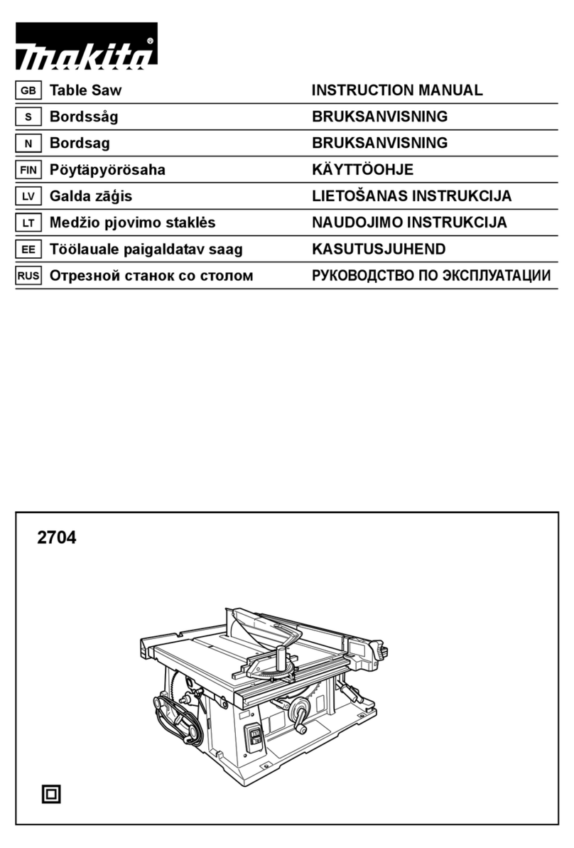
Makita 2704N User manual

2704N
EN Table Saw INSTRUCTION MANUAL 9
ZHCN 台锯 使用说明书 19
ID Mesin Gergaji Meja PETUNJUK PENGGUNAAN 30
MS Gergaji Meja MANUAL ARAHAN 42
VI Máy Cưa Bàn Hoạt Động
Bằng Động Cơ Điện TÀI LIỆU HƯỚNG DẪN 54
TH 65

620 mm
1
525 mm
Fig.1
1
25 mm
2
Fig.2
12
Fig.3
1
Fig.4
1
2
3
Fig.5
12
Fig.6
1
Fig.7
12
3
Fig.8
2

12
Fig.9
(A)
(B)
90
90 45
45
Fig.10
1
Fig.11
1
Fig.12
12
3
4
Fig.13
3
4
2
12
1
2
Fig.14
1
Fig.15
3

1
Fig.16
1
2
Fig.17
2
1
2
Fig.18
1
1
2
Fig.19
21
Fig.20
1
32
Fig.21
12
3
45
Fig.22
1
2
Fig.23
4

12
3
Fig.24
1
2
3
4
5
Fig.25
1
2
3
Fig.26
12
3
3
Fig.27
1
A
B
Fig.28
1
Fig.29
Fig.30
1
2
3
4
Fig.31
5

12
3
4
Fig.32
1
2
Fig.33
Fig.34
120mm
300mm
130mm
50mm
6mm
300mm
130mm
100mm
50mm
9.5mm
50mm
8mm
1
2
3
4
Fig.35
9.5mm
19mm 120mm
40mm
140mm
460mm
1
Fig.36
Fig.37
6

Fig.38
1
Fig.39
Fig.40
1
2
Fig.41
12
34
Fig.42
2
3
1
Fig.43
1
3
2
Fig.44
1
Fig.45
7

Fig.46
1
Fig.47
1
2
3
Fig.48
Fig.49
1
23
Fig.50
8

9ENGLISH
ENGLISH (Original instructions)
SPECIFICATIONS
Model: 2704N
Arbor hole
(Country specic)
30 mm / 25.4 mm
Blade diameter 260 mm
Max. cutting
capacities
bevel 0° 93 mm
bevel 45° 64 mm
No load speed 5,200 min-1
Table size (L x W) with sub tables (R) and
(back)
1,045 mm x 1,066 mm (tables extended)
665 mm x 753 mm (tables stored)
with sub table (R)
without sub table (back)
567 mm x 1,066 mm (table extended)
567 mm x 753 mm (table stored)
Dimensions (L x W x
H) with table(s) not
extended
with sub tables (R) and
(back)
715 mm x 753 mm x 483mm
with sub table (R)
without sub table (back)
665 mm x 753 mm x 483 mm
Net weight 35.2 kg - 37.0 kg
Safety class /II
• Due to our continuing program of research and development, the specications herein are subject to change
without notice.
• Specications may dier from country to country.
• The weight may dier depending on the attachment(s). The lightest and heaviest combination, according to
EPTA-Procedure 01/2014, are shown in the table.
Symbols
The followings show the symbols which may be used
for the equipment. Be sure that you understand their
meaning before use.
Read instruction manual.
DOUBLE INSULATION
Wear safety glasses.
Do not place hand or ngers close to the
blade.
Only for EU countries
Do not dispose of electric equipment
together with household waste material! In
observance of the European Directive, on
Waste Electric and Electronic Equipment
and its implementation in accordance with
national law, electric equipment that have
reached the end of their life must be col-
lected separately and returned to an envi-
ronmentally compatible recycling facility.
Intended use
The tool is intended for cutting in wood.
Straight cutting, bevel cutting, and miter cutting are
available with this tool. This tool is not designed for non-
through cutting.
Power supply
The tool should be connected only to a power supply of
the same voltage as indicated on the nameplate, and
can only be operated on single-phase AC supply. They
are double-insulated and can, therefore, also be used
from sockets without earth wire.
SAFETY WARNINGS
General power tool safety warnings
WARNING: Read all safety warnings, instruc-
tions, illustrations and specications provided
with this power tool. Failure to follow all instructions
listed below may result in electric shock, re and/or
serious injury.

10 ENGLISH
Save all warnings and instruc-
tions for future reference.
The term “power tool” in the warnings refers to your
mains-operated (corded) power tool or battery-operated
(cordless) power tool.
Work area safety
1. Keep work area clean and well lit. Cluttered or
dark areas invite accidents.
2. Do not operate power tools in explosive atmo-
spheres, such as in the presence of ammable
liquids, gases or dust. Power tools create sparks
which may ignite the dust or fumes.
3. Keep children and bystanders away while
operating a power tool. Distractions can cause
you to lose control.
Electrical safety
1. Power tool plugs must match the outlet. Never
modify the plug in any way. Do not use any
adapter plugs with earthed (grounded) power
tools. Unmodied plugs and matching outlets will
reduce risk of electric shock.
2. Avoid body contact with earthed or grounded
surfaces, such as pipes, radiators, ranges and
refrigerators. There is an increased risk of elec-
tric shock if your body is earthed or grounded.
3. Do not expose power tools to rain or wet con-
ditions. Water entering a power tool will increase
the risk of electric shock.
4. Do not abuse the cord. Never use the cord for
carrying, pulling or unplugging the power tool.
Keep cord away from heat, oil, sharp edges
or moving parts. Damaged or entangled cords
increase the risk of electric shock.
5. When operating a power tool outdoors, use an
extension cord suitable for outdoor use. Use of
a cord suitable for outdoor use reduces the risk of
electric shock.
6. If operating a power tool in a damp location
is unavoidable, use a residual current device
(RCD) protected supply. Use of an RCD reduces
the risk of electric shock.
7. Use of power supply via an RCD with a rated
residual current of 30 mA or less is always
recommended.
8. Power tools can produce electromagnetic
elds (EMF) that are not harmful to the user.
However, users of pacemakers and other similar
medical devices should contact the maker of their
device and/or doctor for advice before operating
this power tool.
9. Do not touch the power plug with wet hands.
10. If the cord is damaged, have it replaced by the
manufacturer or his agent in order to avoid a
safety hazard.
Personal safety
1. Stay alert, watch what you are doing and use
common sense when operating a power tool.
Do not use a power tool while you are tired or
under the inuence of drugs, alcohol or med-
ication. A moment of inattention while operating
power tools may result in serious personal injury.
2. Use personal protective equipment. Always
wear eye protection. Protective equipment such
as a dust mask, non-skid safety shoes, hard hat or
hearing protection used for appropriate conditions
will reduce personal injuries.
3. Prevent unintentional starting. Ensure the
switch is in the o-position before connecting
to power source and/or battery pack, picking
up or carrying the tool. Carrying power tools with
your nger on the switch or energising power tools
that have the switch on invites accidents.
4. Remove any adjusting key or wrench before
turning the power tool on. A wrench or a key left
attached to a rotating part of the power tool may
result in personal injury.
5. Do not overreach. Keep proper footing and
balance at all times. This enables better control
of the power tool in unexpected situations.
6. Dress properly. Do not wear loose clothing or
jewellery. Keep your hair and clothing away
from moving parts. Loose clothes, jewellery or
long hair can be caught in moving parts.
7. If devices are provided for the connection of
dust extraction and collection facilities, ensure
these are connected and properly used. Use of
dust collection can reduce dust-related hazards.
8. Do not let familiarity gained from frequent use
of tools allow you to become complacent and
ignore tool safety principles. A careless action
can cause severe injury within a fraction of a
second.
9. Always wear protective goggles to protect
your eyes from injury when using power tools.
The goggles must comply with ANSI Z87.1 in
the USA, EN 166 in Europe, or AS/NZS 1336
in Australia/New Zealand. In Australia/New
Zealand, it is legally required to wear a face
shield to protect your face, too.
It is an employer's responsibility to enforce
the use of appropriate safety protective equip-
ments by the tool operators and by other per-
sons in the immediate working area.
Power tool use and care
1. Do not force the power tool. Use the correct
power tool for your application. The correct
power tool will do the job better and safer at the
rate for which it was designed.
2. Do not use the power tool if the switch does
not turn it on and o. Any power tool that cannot
be controlled with the switch is dangerous and
must be repaired.
11 ENGLISH
3. Disconnect the plug from the power source
and/or remove the battery pack, if detachable,
from the power tool before making any adjust-
ments, changing accessories, or storing power
tools. Such preventive safety measures reduce
the risk of starting the power tool accidentally.
4. Store idle power tools out of the reach of chil-
dren and do not allow persons unfamiliar with
the power tool or these instructions to operate
the power tool. Power tools are dangerous in the
hands of untrained users.
5. Maintain power tools and accessories. Check
for misalignment or binding of moving parts,
breakage of parts and any other condition that
may aect the power tool’s operation. If dam-
aged, have the power tool repaired before use.
Many accidents are caused by poorly maintained
power tools.
6. Keep cutting tools sharp and clean. Properly
maintained cutting tools with sharp cutting edges
are less likely to bind and are easier to control.
7. Use the power tool, accessories and tool bits
etc. in accordance with these instructions, tak-
ing into account the working conditions and
the work to be performed. Use of the power tool
for operations dierent from those intended could
result in a hazardous situation.
8. Keep handles and grasping surfaces dry,
clean and free from oil and grease. Slippery
handles and grasping surfaces do not allow for
safe handling and control of the tool in unexpected
situations.
9. When using the tool, do not wear cloth work
gloves which may be entangled. The entangle-
ment of cloth work gloves in the moving parts may
result in personal injury.
Service
1. Have your power tool serviced by a qualied
repair person using only identical replacement
parts. This will ensure that the safety of the power
tool is maintained.
2. Follow instruction for lubricating and chang-
ing accessories.
Safety instructions for table saws
Guarding related warnings
1. Keep guards in place. Guards must be in work-
ing order and be properly mounted. A guard
that is loose, damaged, or is not functioning cor-
rectly must be repaired or replaced.
2. Make sure the saw blade is not contacting the
guard, riving knife or the workpiece before the
switch is turned on. Inadvertent contact of these
items with the saw blade could cause a hazardous
condition.
3. Adjust the riving knife as described in this
instruction manual. Incorrect spacing, position-
ing and alignment can make the riving knife inef-
fective in reducing the likelihood of kickback.
4. For the riving knife and anti-kickback pawls to
work, they must be engaged in the workpiece.
The riving knife and anti-kickback pawls are inef-
fective when cutting workpieces that are too short
to be engaged with the riving knife and anti-kick-
back pawls. Under these conditions a kickback
cannot be prevented by the riving knife and anti-
kickback pawls.
5. Use the appropriate saw blade for the riving
knife. For the riving knife to function properly, the
saw blade diameter must match the appropriate
riving knife and the body of the saw blade must be
thinner than the thickness of the riving knife and
the cutting width of the saw blade must be wider
than the thickness of the riving knife.
Cutting procedures warnings
1. DANGER: Never place your ngers or
hands in the vicinity or in line with the saw
blade. A moment of inattention or a slip could
direct your hand towards the saw blade and result
in serious personal injury.
2. Feed the workpiece into the saw blade only
against the direction of rotation. Feeding the
workpiece in the same direction that the saw blade
is rotating above the table may result in the work-
piece, and your hand, being pulled into the saw
blade.
3. Never use the mitre gauge to feed the work-
piece when ripping and do not use the rip
fence as a length stop when cross cutting with
the mitre gauge. Guiding the workpiece with the
rip fence and the mitre gauge at the same time
increases the likelihood of saw blade binding and
kickback.
4. When ripping, always apply the workpiece
feeding force between the fence and the saw
blade. Use a push stick when the distance
between the fence and the saw blade is less
than 150 mm, and use a push block when this
distance is less than 50 mm. “Work helping”
devices will keep your hand at a safe distance
from the saw blade.
5. Use only the push stick provided by the manu-
facturer or constructed in accordance with the
instructions. This push stick provides sucient
distance of the hand from the saw blade.
6. Never use a damaged or cut push stick. A
damaged push stick may break causing your hand
to slip into the saw blade.
7. Do not perform any operation “freehand”.
Always use either the rip fence or the mitre
gauge to position and guide the workpiece.
“Freehand” means using your hands to support or
guide the workpiece, in lieu of a rip fence or mitre
gauge. Freehand sawing leads to misalignment,
binding and kickback.
8. Never reach around or over a rotating saw
blade. Reaching for a workpiece may lead to
accidental contact with the moving saw blade.
9. Provide auxiliary workpiece support to the rear
and/or sides of the saw table for long and/or
wide workpieces to keep them level. A long and/
or wide workpiece has a tendency to pivot on the
table’s edge, causing loss of control, saw blade
binding and kickback.

12 ENGLISH
10. Feed workpiece at an even pace. Do not bend
or twist the workpiece. If jamming occurs, turn
the tool o immediately, unplug the tool then
clear the jam. Jamming the saw blade by the
workpiece can cause kickback or stall the motor.
11. Do not remove pieces of cut-o material while
the saw is running. The material may become
trapped between the fence or inside the saw blade
guard and the saw blade pulling your ngers into
the saw blade. Turn the saw o and wait until the
saw blade stops before removing material.
12. Use an auxiliary fence in contact with the table
top when ripping workpieces less than 2 mm
thick. A thin workpiece may wedge under the rip
fence and create a kickback.
Kickback causes and related warnings
Kickback is a sudden reaction of the workpiece due to a
pinched, jammed saw blade or misaligned line of cut in
the workpiece with respect to the saw blade or when a
part of the workpiece binds between the saw blade and
the rip fence or other xed object.
Most frequently during kickback, the workpiece is lifted
from the table by the rear portion of the saw blade and
is propelled towards the operator.
Kickback is the result of saw misuse and/or incorrect
operating procedures or conditions and can be avoided
by taking proper precautions as given below.
1. Never stand directly in line with the saw blade.
Always position your body on the same side of
the saw blade as the fence. Kickback may propel
the workpiece at high velocity towards anyone
standing in front and in line with the saw blade.
2. Never reach over or in back of the saw blade
to pull or to support the workpiece. Accidental
contact with the saw blade may occur or kickback
may drag your ngers into the saw blade.
3. Never hold and press the workpiece that is
being cut o against the rotating saw blade.
Pressing the workpiece being cut o against the
saw blade will create a binding condition and
kickback.
4. Align the fence to be parallel with the saw
blade. A misaligned fence will pinch the workpiece
against the saw blade and create kickback.
5. Use extra caution when making a cut into blind
areas of assembled workpieces. The protrud-
ing saw blade may cut objects that can cause
kickback.
6. Support large panels to minimise the risk of
saw blade pinching and kickback. Large panels
tend to sag under their own weight. Support(s)
must be placed under all portions of the panel
overhanging the table top.
7. Use extra caution when cutting a workpiece
that is twisted, knotted, warped or does not
have a straight edge to guide it with a mitre
gauge or along the fence. A warped, knotted,
or twisted workpiece is unstable and causes mis-
alignment of the kerf with the saw blade, binding
and kickback.
8. Never cut more than one workpiece, stacked
vertically or horizontally. The saw blade could
pick up one or more pieces and cause kickback.
9. When restarting the saw with the saw blade in
the workpiece, centre the saw blade in the kerf
so that the saw teeth are not engaged in the
material. If the saw blade binds, it may lift up the
workpiece and cause kickback when the saw is
restarted.
10. Keep saw blades clean, sharp, and with su-
cient set. Never use warped saw blades or saw
blades with cracked or broken teeth. Sharp and
properly set saw blades minimise binding, stalling
and kickback.
Table saw operating procedure warnings
1. Turn o the table saw and disconnect the
power cord when removing the table insert,
changing the saw blade or making adjust-
ments to the riving knife, anti-kickback pawls
or saw blade guard, and when the machine
is left unattended. Precautionary measures will
avoid accidents.
2. Never leave the table saw running unattended.
Turn it o and don’t leave the tool until it
comes to a complete stop. An unattended run-
ning saw is an uncontrolled hazard.
3. Locate the table saw in a well-lit and level area
where you can maintain good footing and
balance. It should be installed in an area that
provides enough room to easily handle the
size of your workpiece. Cramped, dark areas,
and uneven slippery oors invite accidents.
4. Frequently clean and remove sawdust from
under the saw table and/or the dust collection
device. Accumulated sawdust is combustible and
may self-ignite.
5. The table saw must be secured. A table saw that
is not properly secured may move or tip over.
6. Remove tools, wood scraps, etc. from the table
before the table saw is turned on. Distraction or
a potential jam can be dangerous.
7. Always use saw blades with correct size and
shape (diamond versus round) of arbour
holes. Saw blades that do not match the mounting
hardware of the saw will run o-centre, causing
loss of control.
8. Never use damaged or incorrect saw blade
mounting means such as anges, saw blade
washers, bolts or nuts. These mounting means
were specially designed for your saw, for safe
operation and optimum performance.
9. Never stand on the table saw, do not use it as
a stepping stool. Serious injury could occur if the
tool is tipped or if the cutting tool is accidentally
contacted.
10. Make sure that the saw blade is installed to
rotate in the proper direction. Do not use
grinding wheels, wire brushes, or abrasive
wheels on a table saw. Improper saw blade
installation or use of accessories not recom-
mended may cause serious injury.
Additional instructions
1. Only use the saw blades that are marked with
a speed equal or higher than the speed marked
on the tool.
2. Select the correct saw blade for the material to
be cut.

13 ENGLISH
3. Wear gloves when handling saw blades.
4. Clean the spindle, anges (especially the
installing surface) and hex nut before install-
ing the blade. Poor installation may cause vibra-
tion/wobbling or slippage of the blade.
5. Do not cut metal objects such as nails and
screws. Inspect for and remove all nails,
screws and other foreign material from the
workpiece before operation.
6. NEVER permit anyone else to stand in line with
the path of the saw blade.
7. Before using the tool on an actual workpiece,
let it run for a while. Watch for vibration or
wobbling that could indicate poor installation
or a poorly balanced blade.
8. The tool should not be used for slotting, rab-
betting or grooving.
9. Replace the table insert when worn.
10. Always store the push-stick when it is not in
use.
11. Knock out any loose knots from workpiece
BEFORE beginning to cut.
12. Some dust created from operation contains
chemicals known to cause cancer, birth
defects or other reproductive harm. Some
examples of these chemicals are:
— lead from lead-based-painted material
and,
— arsenic and chromium from chemical-
ly-treated lumber.
Your risk from these exposures varies,
depending on how often you do this type
of work. To reduce your exposure to these
chemicals: work in a well ventilated area and
work with approved safety equipment, such as
those dust masks that are specially designed
to lter out microscopic particles.
13. Always make sure that sub guard is down and
at against saw-table before plugging in the
tool.
14. Inspect extension cords periodically and
replace if damaged.
15. (For European countries only)
Use only saw blades recommended by the
manufacturer and which conform to EN847-1.
INSTALLATION
Positioning table saw
► Fig.1: 1. Hole diameter 8 mm
► Fig.2: 1. 6 mm Std. washer 2. No.10 wood screw
40 mm min. length
► Fig.3: 1. 6 mm Std. washer 2. 6 mm Mounting bolt
& Nut tighten securely
Locate the table saw in a well lit and level area where
you can maintain good footing and balance. It should
be installed in an area that leaves enough room to
easily handle the size of your workpieces. The table
saw should be secured with four screws or bolts to the
work bench or table saw stand using the holes provided
in the bottom of the table saw. When securing the table
saw on the work bench, make sure that there is an
opening in the top of the work bench the same size as
the opening in the bottom of the table saw so the saw-
dust can drop through.
If during operation there is any tendency for the table
saw to tip over, slide or move, the work bench or table
saw stand should be secured to the oor.
Storing accessories
► Fig.4: 1. Miter gauge
► Fig.5: 1. Rip fence 2. Push stick 3. Anti-kickback
pawls
The miter gauge, saw blade and wrenches can be
stored on the left side of the base. Also the rip fence,
push stick, and anti-kickback pawls can be stored at the
right side of the base.
FUNCTIONAL
DESCRIPTION
CAUTION: Always be sure that the tool is
switched o and unplugged before adjusting or
checking function on the tool.
Blade guard
WARNING: Never defeat or remove the blade
guard. An exposed blade as a result of defeated
guarding may result in serious personal injury during
operation.
WARNING: Never use the tool if the blade
guard is damaged, faulty or removed. Operation of
the tool with a damaged, faulty or removed guard may
result in serious personal injury.
► Fig.6: 1. Blade guard 2. Sub guard
When cutting, push the workpiece toward the blade
with the lower edge of the sub guard contacting with the
main table. As the workpiece is fed, the blade guard and
the sub guard goes over the edge of the workpiece.
In the interest of your personal safety, always maintain
the blade guard and sub guard in good condition. Any
irregular operation of the blade guard and sub guard
should be corrected immediately. Check to assure that
the blade guard and the sub guard are down and the
lower edge of the sub guard contacts with the main
table when the workpiece is not fed.

14 ENGLISH
If the see-through parts become dirty, or sawdust
adheres to them in such a way that the blade and/or
workpiece is no longer easily visible, unplug the tool
and clean the see-through parts carefully with a damp
cloth. Do not use solvents or any petroleum-based
cleaners because this may cause damage to the parts.
If see-through parts become discolored through age or
UV light exposure, contact a Makita service center for
a new parts. DO NOT DEFEAT OR REMOVE BLADE
GUARD AND SUB GUARD.
Adjusting the depth of cut
► Fig.7: 1. Handle
The depth of cut may be adjusted by turning the handle.
Turn the handle clockwise to raise the saw blade or
counterclockwise to lower it.
NOTE: Use a shallow depth setting when cutting thin
materials in order to obtain a cleaner cut.
Adjusting the bevel angle
► Fig.8: 1. Lock lever 2. Arrow pointer 3. Handwheel
Loosen the lock lever counterclockwise and turn the
handwheel until the desired angle (0° - 45°) is obtained.
The bevel angle is indicated by the arrow pointer.
After obtaining the desired angle, tighten the lock lever
clockwise to secure the adjustment.
CAUTION: After adjusting the bevel angle, be
sure to tighten the lock lever securely.
Adjusting positive stops
► Fig.9: 1. 90°Adjusting screw 2. 45°Adjusting screw
► Fig.10
The tool is equipped with positive stops at 90° and 45°
to the table surface. To check and adjust the positive
stops, proceed as follows:
Move the handwheel as far as possible by turning it.
Place a triangular rule on the table and check to see
if the saw blade is at 90° or 45° to the table surface. If
the saw blade is at an angle shown in Fig. A, turn the
adjusting screws clockwise; if it is at an angle shown in
Fig. B, turn the adjusting screws counterclockwise to
adjust the positive stops.
After adjusting the positive stops, set the saw blade at
90° to the table surface. Then adjust the arrow pointer
so that its right edge is aligned to the 0° graduation.
► Fig.11: 1. Arrow pointer
Switch action
► Fig.12: 1. Switch
CAUTION: Before operation, make sure that
the tool is turned on and o.
To start the tool, press the ON ( I ) button.
To stop it, press the OFF ( O ) button.
Sub fence (rip fence)
► Fig.13: 1. Clamping screw 2. Rip fence 3. Sub
fence 4. Rail
If the rip fence comes close to the saw blade, use the
sub fence to support the workpiece. Loosen the clamp-
ing screw and slide the sub fence out of the rail. Attach
the sub fence as illustrated and tighten the clamping
screws.
When the rip fence is attached to the left side of the
saw blade, switch the sub fence position. Remove the
clamping screws, sub fence, and rail from the rip fence.
Loosely attach the rail on the right side of the rip fence
using the removed clamping screws. After that, attach
the sub fence and tighten the clamping screws.
► Fig.14: 1. Rip fence 2. Sub fence 3. Clamping
screw 4. Rail
Sub table (R)
► Fig.15: 1. Lever
► Fig.16: 1. Sub table (R)
This tool is provided with the sub table (R) on the right
side of the main table. To use the sub table (R), raise
both levers on the front right side, pull out the table (R)
fully and then lower the levers to secure it.
When using the sub table (R ), locate the scale plate
on the sub table after loosening the screw on it with
a screwdriver so that it becomes successive with the
scale plate on the main table.
► Fig.17: 1. Scale plate 2. Screw
Sub table (back)
Optional accessory
► Fig.18: 1. Sub table (back) 2. Screw
To use the sub table (back), loosen the screws on the
left and right hand sides under the table and pull it out
backwards to the desired length. At the desired length,
tighten the screws securely.
NOTE: When using the sub table (back) during use of
the rip fence, pull out the sub table (back) more than
50 mm so that it does not hit against the top end of
the rip fence.
Sub table (L)
Optional accessory
► Fig.19: 1. Screw 2. Sub table (L)
Sub table (L) (optional accessory) can be installed on
the left side of the table to obtain wider space.
Anti-kickback pawls
WARNING: Use the Antikickback pawls when-
ever possible during the through cutting opera-
tions. This will help prevent the material from being
pushed forward into the operator during a kickback
situation which may result in serious personal injury.
► Fig.20: 1. Antikickback pawl 2. Clamp

15 ENGLISH
To remove the anti-kickback pawls from the tool, loosen
the clamp on the root of the antikickback pawls and
then pull them out. To install, perform the removal pro-
cedure in reverse.
ASSEMBLY
CAUTION: Always be sure that the tool is
switched o and unplugged before carrying out
any work on the tool.
Installing or removing saw blade
CAUTION: Always be sure that the tool is
switched o and unplugged before installing or
removing the saw blade.
CAUTION: Use only the Makita wrench pro-
vided to install or remove the saw blade. Failure
to do so may result in overtightening or insucient
tightening of the hex bolt. This could cause an injury.
CAUTION: Use the following saw blade. Do
not use saw blades which do not comply with the
characteristics specied in these instructions.
Diameter Blade thickness Kerf
260 mm Less than 1.9 mm More than 2.1 mm
1. Loosen the screw on the table insert and remove
it.
2. Hold the outer ange with the oset wrench and
loosen the hex nut counterclockwise with the wrench.
Then remove the outer ange.
► Fig.21: 1. Oset wrench 2. Hex nut 3. Wrench
3. Assemble the inner ange, ring, saw blade, outer
ange and hex nut onto the arbor, making sure that the
teeth of the blade are pointing down at the front of the
table. Always install the hex nut with its recessed side
facing the outer ange.
► Fig.22: 1. Inner ange 2. Ring 3. Saw blade
4. Outer ange 5. Hex nut
CAUTION: Be sure that the saw blade is
installed so that the teeth are aligned in the cut-
ting (turning) direction.
CAUTION: Check the arbor hole diameter of
the saw blade before installing the saw blade.
Always use the correct ring for the arbor hole of
the saw blade you intend to use. The size of the
supplied ring(s) varies depending on the country.
• For tool for a 30 mm hole-diameter saw blade,
the ring 30 mm in outer diameter is provided.
• For tool for a 25.4 mm and 25 mm hole-diameter
saw blade, the silver and black rings are pro-
vided. Use the silver ring for 25.4 mm hole-di-
ameter saw blade and the black ring for 25 mm
hole-diameter saw blade.
4. To secure the saw blade in place, hold the outer
ange with the oset wrench, then tighten the hex nut
clockwise with the wrench. BE SURE TO TIGHTEN
THE HEX NUT SECURELY.
► Fig.23: 1. Oset wrench 2. Wrench
CAUTION: Keep the ange surface clean of
dirt or other adhering matter; it could cause blade
slippage.
CAUTION: Be sure to hold the hex nut care-
fully with the wrench. If your grip should slip, the
wrench may come o the hex nut, and your hand
could strike the sharp blade edges.
5. Attach the table insert in place with the screw.
Adjusting the riving knife
CAUTION: If the saw blade and riving knife
are not aligned properly, a dangerous pinching
condition may result during operation. Make sure
they are properly aligned. You could suer serious
personal injury while using the tool without a properly
aligned riving knife.
CAUTION: NEVER make any adjustments
while tool is running. Disconnect the tool before
making any adjustments.
CAUTION: Don't remove the riving knife.
► Fig.24: 1. Blade guard 2. Riving knife 3. Screw
The riving knife position is factory-adjusted so that
the saw blade and riving knife will be in a straight line.
However, you need to adjust it if the saw blade and
riving knife are not in a straight line.
Loosen the screw on the table insert and remove it from
the main table. Loosen the hex bolts (B) and adjust the
blade guard mounting portion (stay) so that the riving
knife is aligned directly behind the saw blade. Then
tighten the hex bolts (B) to secure the stay and put the
table insert in place.
► Fig.25: 1. Blade 2. These two clearances should be
equal. 3. Riving knife 4. Hex bolts (B) 5. Hex
bolts (A)
There must be a clearance of about 4 - 5 mm between
the riving knife and the blade teeth. Loosen the hex
bolts (A), adjust the riving knife accordingly and tighten
the hex bolts (A) securely. Attach the table insert on the
table with the screw, then check to see that the blade
guard works smoothly before cutting.
► Fig.26: 1. Riving knife 2. Blade guard 3. 4 mm -
5mm clearance
Installing and adjusting rip fence
► Fig.27: 1. Hook 2. Knob 3. Guide rail
1. Fit the hook on the tip of the rip fence into the far
guide rail on the table or sub table (R) and install and
push the rip fence forward so that the fence holder
engages with the nearmost guide rail.

16 ENGLISH
2. To slide the rip fence on the guide rail sideways,
return the knob on the fence holder fully without pulling
the lever on the knob.
To secure the rip fence, pivot fully the knob on the fence
holder.
3. To remove the rip fence, pull the lever on the knob
and pivot the knob fully forward while pulling the lever.
To check if the rip fence is parallel with the saw blade,
secure the rip fence 2 - 3 mm from the saw blade. Raise
the blade up to maximum elevation. Mark one of the
blade teeth with a crayon. Measure the distance (A)
and (B) between the rip fence and saw blade. Take both
measurements using the tooth marked with the crayon.
These two measurements should be identical. If the
rip fence is not parallel with the saw blade, proceed as
follows:
► Fig.28: 1. Scale
1. Position the rip fence in the sliding position.
2. Loosen the two hex bolts on the rip fence with the
hex wrench provided.
► Fig.29: 1. Hex bolts
3. Adjust the rip fence until it becomes parallel with
the saw blade.
4. Pivot down the knob on the rip fence toward the
operator.
5. Tighten the two hex bolts on the rip fence.
► Fig.30
CAUTION: Be sure to adjust the rip fence so
that it is parallel with the saw blade, or a danger-
ous kickback condition may occur.
When the rip fence cannot be secured solidly, adjust it
according to the following procedure.
1. Set the rip fence on the table and then pivot the
knob on the half way of its travel (moving position).
Tighten the screw (A) until the rip fence is immobilized.
Then loosen a 1/4 to 1/2 turn.
► Fig.31: 1. Rip fence 2. Released position 3. Moving
position 4. Lock position
► Fig.32: 1. Rip fence 2. Moving position 3. Screw (B)
4. Screw (A)
2. Tighten the screw (B) fully and then loosen about
2 full revolutions.
3. Lock the rip fence by fully pivoting the knob on the
fence holder (lock position).
4. Make sure that the rip fence can be installed and
removed in the original position (released position).
5. Make sure that the rip fence can be slid smoothly
with no wobble when the knob is on half way of its
travel.
NOTICE: Be careful not to tighten screws with
more than tightening amount specied in the
above instructions. Failure to do so may damage
the fastened parts.
Bring the rip fence up ush against the side of the saw
blade. Make sure that the guideline on the fence holder
points to the 0 graduation. If the guideline does not
point to the 0 graduation, loosen the screw on the scale
plate and adjust the scale plate.
► Fig.33: 1. Guideline 2. Screws
Connecting to vacuum cleaner
Cleaner operations can be performed by connecting the
tool to Makita vacuum cleaner or dust collector.
► Fig.34
OPERATION
CAUTION: Always use “work helpers” such
as push sticks and push blocks when there is a
danger that your hands or ngers will come close
to the saw blade.
CAUTION: Always hold the workpiece rmly
with the table and the rip fence or miter gauge. Do
not bend or twist it while feeding. If the workpiece
is bent or twisted, dangerous kickbacks may occur.
CAUTION: NEVER withdraw the workpiece
while the saw blade is running. If you must with-
draw the workpiece before completing a cut, rst
switch the tool o while holding the workpiece
rmly. Wait until the saw blade has come to a
complete stop before withdrawing the workpiece.
Failure to do so may cause dangerous kickbacks.
CAUTION: NEVER remove cut-o material
while the saw blade is running.
CAUTION: NEVER place your hands or n-
gers in the path of the saw blade. Be especially
careful with bevel cuts.
CAUTION: Always secure the rip fence rmly,
or dangerous kickbacks may occur.
CAUTION: Always use “work helpers” such
as push sticks and push blocks when cutting
small or narrow workpieces.
Work helpers
Push sticks, push blocks or auxiliary fence are types of
“work helpers”. Use them to make safe, sure cuts with-
out the need for the operator to contact the saw blade
with any part of the body.
Push block
► Fig.35: 1. Face/edge parallel 2. Handle 3. Wood
screw 4. Glue together
Use a 19 mm piece of plywood.
Handle should be in center of plywood piece. Fasten
with glue and wood screws as shown. Small piece
9.5 mm x 8 mm x 50 mm of wood must always be glued
to plywood to keep the saw blade from dulling if the
operator cuts into push block by mistake. (Never use
nails in push block.)

17 ENGLISH
Auxiliary fence
► Fig.36: 1. Face/edge parallel
Make auxiliary fence from 9.5 mm and 19 mm plywood
pieces.
Ripping
CAUTION: When ripping, remove the miter
gauge from the table.
CAUTION: When cutting long or large work-
pieces, always provide adequate support behind
the table. DO NOT allow a long board to move
or shift on the table. This will cause the saw blade
to bind and increase the possibility of kickback and
personal injury. The support should be at the same
height as the table.
CAUTION: Do not perform bevel ripping on
the bevelling side of the saw blade.
1. Adjust the depth of cut a bit higher than the thick-
ness of the workpiece.
► Fig.37
2. Position the rip fence to the desired width of rip
and lock in place by pivoting the knob. Before ripping,
make sure the rear end of the rip fence is secured
rmly. If it is not secured enough, follow the procedures
in the section titled “Installing and adjusting rip fence”.
3. Turn the tool on and gently feed the workpiece into
the saw blade along with the rip fence.
When the width of rip is 150 mm and wider, carefully
use your right hand to feed the workpiece. Use your left
hand to hold the workpiece in position against the rip
fence.
► Fig.38
When the width of rip is 65 mm - 150 mm wide, use the
push stick to feed the workpiece.
► Fig.39: 1. Push stick
When the width of rip is narrower than 65 mm, the push
stick cannot be used because the push stick will strike
the blade guard. Use the auxiliary fence and push
block. Attach the auxiliary fence to the rip fence with two
“C” clamps.
Feed the workpiece by hand until the end is about
25 mm from the front edge of the table.
► Fig.40
Continue to feed using the push block on the top of the
auxiliary fence until the cut is complete.
► Fig.41: 1. Push block 2. Auxiliary fence
Cross cutting
CAUTION: When making a crosscut, remove
the rip fence from the table.
CAUTION: When cutting long or large work-
pieces, always provide adequate support to the
sides of the table. The support should be at the
same height as the table.
CAUTION: Always keep hands away from
path of blade.
Miter gauge
► Fig.42: 1. Cross cutting 2. Mitering 3. Bevel cutting
4. Compound mitering (angles)
Use the miter gauge for the 4 types of cutting shown in
the gure.
CAUTION: Secure the knob on the miter
gauge carefully.
CAUTION: Avoid creep of workpiece and
gauge by rm workholding arrangement, espe-
cially when cutting at an angle.
CAUTION: NEVER hold or grasp the intended
“cut-o” portion of the workpiece.
CAUTION: Always adjust the distance
between the end of the miter gauge and the saw
blade not to exceed 15 mm.
Miter gauge positive stop
► Fig.43: 1. Screw for positive stop 2. Small plate
3. Knob
Miter gauge is provided with positive stops at 90°,
45°right and left miter angles for quick setting of miter
angles.
To set the miter angle, loosen the knob on the miter
gauge.
Raise the small plate on the miter gauge for free setting.
Turn the miter gauge to the desired miter angle. Return
the small plate on the miter gauge to the original posi-
tion and tighten the knob clockwise securely.
Use of miter gauge
► Fig.44: 1. Groove 2. Miter gauge 3. Knob
Slide the miter gauge into the thick grooves in the table.
Loosen the knob on the gauge and align to desired
angle (0° to 60°). Bring stock ush up against fence and
feed gently forward into the saw blade.
Sub gauge (miter gauge)
► Fig.45: 1. Sub gauge
The sub gauge on the miter gauge prevents the work-
piece from wobbling. Loosen the screw on the miter
gauge and adjust the sub gauge position.
Carrying tool
► Fig.46
Make sure that the tool is unplugged.
Carry the tool by holding the tool part shown in the
gure.
CAUTION: Always secure all moving portions
before carrying the tool.
CAUTION: Before the carrying the tool, make
sure that the blade guard and the sub guard are
down and the lower edge of the sub guard con-
tacts with the main table.

18 ENGLISH
MAINTENANCE
CAUTION: Always be sure that the tool is
switched o and unplugged before attempting to
perform inspection or maintenance.
NOTICE: Never use gasoline, benzine, thinner,
alcohol or the like. Discoloration, deformation or
cracks may result.
Cleaning
Clean out sawdust and chips from time to time.
Carefully clean the blade guard and moving parts inside
the table saw.
When removing the sawdust accumulated under the
saw blade, remove the table insert and use an air
duster to blow out the sawdust from the connector for a
vacuum cleaner.
Lubrication
To keep the table saw in tip-top running condition, and
to assure maximum service life, oil or grease the mov-
ing parts and rotating parts from time to time.
Lubrication places:
• Threaded shaft to elevate the saw blade
• Hinge to rotate the frame
• Elevation guide shafts on motor
• Gear to elevate the saw blade
• Guide rails for the rip fence
• Shaft of the sub table (R) locking levers
• Sliding part of the sub table (R)
Replacing carbon brushes
Check the carbon brushes regularly.
Replace them when they wear down to the limit mark.
Keep the carbon brushes clean and free to slip in the
holders. Both carbon brushes should be replaced at the
same time. Use only identical carbon brushes.
► Fig.47: 1. Limit mark
1. Store the sub table (R). Remove the rip fence if it
is stored.
2. Loosen the lock lever and turn the handwheel
until the saw head is tilted to 45° bevel angle. After that,
tighten the lock lever.
► Fig.48: 1. Rip fence 2. Lock lever 3. Handwheel
3. Stand the tool on its right side.
► Fig.49
4. Loosen the screws on the bottom plate and
remove it.
5. Loosen the brush holder caps using a screwdriver
and remove the worn carbon brushes.
► Fig.50: 1. Bottom plate 2. Brush holder cap
3. Screwdriver
6. Insert the new carbon brushes and secure the
brush holder caps.
7. Attach the bottom plate with screws and carefully
lay the tool on its bottom. Store the rip fence if removed.
To maintain product SAFETY and RELIABILITY,
repairs, any other maintenance or adjustment should
be performed by Makita Authorized or Factory Service
Centers, always using Makita replacement parts.
OPTIONAL
ACCESSORIES
CAUTION: These accessories or attachments
are recommended for use with your Makita tool
specied in this manual. The use of any other
accessories or attachments might present a risk of
injury to persons. Only use accessory or attachment
for its stated purpose.
If you need any assistance for more details regard-
ing these accessories, ask your local Makita Service
Center.
• Steel & Carbide-tipped saw blades
• Sub table (L)
• Sub table (back)
• Rip fence
• Miter gauge
• Oset wrench 13-22
• Wrench 19
• Hex wrench 5
• Joint (for connecting to dust collector)
• Table stand set
Refer to the instruction manual for table saw stand
that is provided with the table saw stand as an optional
accessory.
NOTE: Some items in the list may be included in the
tool package as standard accessories. They may
dier from country to country.

19
中文简体
中文简体 (原本)
规格
型号: 2704N
轴孔
(规格因国家而异)
30 mm / 25.4 mm
锯片直径 260 mm
最大切割能力 0°斜切 93 mm
45°斜切 64 mm
空载速度 5,200/min
台面尺寸
(长×宽)
含 副 台 面( 右 侧 )和
(背面)
1,045 mm x 1,066 mm(台面展开)
665 mm x 753 mm(台面收起)
含 副 台 面( 右 侧 )
不 含 副 台 面( 背 面 )
567 mm x 1,066 mm(台面展开)
567 mm x 753 mm (台面收起)
尺寸(长x宽x
高)(台面未
展开)
含副台面(右侧)
和(背面)
715 mm x 753 mm x 483mm
含 副 台 面( 右 侧 )
不 含 副 台 面( 背 面 )
665 mm x 753 mm x 483 mm
净重 35.2 kg - 37.0 kg
安全等级 /II
• 生产者保留变更规格不另行通知之权利。
• 规格可能因销往国家之不同而异。
• 重量因附件而异。根据EPTA-Procedure 01/2014,最重与最轻的组合见表格。
符号
以下显示本设备可能会使用的符号。在使用
工具之前,请务必理解其含义。
阅读使用说明书。
II类工具
佩带安全眼镜。
请勿将手或手指靠近锯片。
仅限于欧盟国家
请勿将电气设备与家庭普通废
弃物一同丢弃!请务必遵守欧
洲关于废弃电子电气设备的指
令,根据各国法律法规执行。
达到使用寿命的电气设备必须
分类回收至符合环境保护规定
的再循环机构。
用途
本工具用于切割木材。
本工具可进行直线切割、斜切角切割和斜切。本
工具不用于非穿透切割。
电源
本工具只可连接电压与铭牌所示电压相同的
电源,且仅可使用单相交流电源。本工具双
重绝缘,因此也可用于不带接地线的插座。

20
中文简体
安全警告
电动工具通用安全警告
警告: 阅读随电动工具提供的所有安全
警告、说明、图示和规定。不遵照以下所列
说明会导致电击、着火和/或严重伤害。
保存所有警告和说明书以备
查阅。
警告中的术语“电动工具”是指市电驱动
(有线)电动工具或电池驱动(无线)电动
工具。
工作场地的安全
1. 保持工作场地清洁和明亮。杂乱和黑暗
的场地会引发事故。
2. 不要在易爆环境,如有易燃液体、气体
或粉尘的环境下操作电动工具。电动工
具产生的火花会点燃粉尘或气体。
3. 操作电动工具时,远离儿童和旁观者。注
意力不集中会使你失去对工具的控制。
电气安全
1. 电动工具插头必须与插座相配。绝不能
以任何方式改装插头。需接地的电动工
具不能使用任何转换插头。未经改装的
插头和相配的插座将降低电击风险。
2. 避免人体接触接地表面,如管道、散热
片和冰箱。如果你身体接触接地表面会
增加电击风险。
3. 不得将电动工具暴露在雨中或潮湿环境
中。水进入电动工具将增加电击风险。
4. 不得滥用软线。绝不能用软线搬运、拉
动电动工具或拔出其插头。使软线远离
热源、油、锐边或运动部件。受损或缠
绕的软线会增加电击风险。
5. 当在户外使用电动工具时,使用适合户
外使用的延长线。适合户外使用的电线
将降低电击风险。
6. 如果无法避免在潮湿环境中操作电动工
具,应使用带有剩余电流装置(RCD)
保护的电源。RCD的使用可降低电击
风险。
7. 始终建议通过额定剩余电流为30 mA或
以下的RCD来使用电源。
8. 电动工具会产生对用户无害的电磁场
(EMF)。但是,起搏器和其他类似医
疗设备的用户应在操作本电动工具前咨
询其设备的制造商和/或医生寻求建议。
9. 请勿用湿手触摸电源插头。
10. 如果导线破损,则由制造商或其代理商
更换以避免安全隐患。
人身安全
1. 保持警觉,当操作电动工具时关注所从
事的操作并保持清醒。当你感到疲倦,
或在有药物、酒精或治疗反应时,不要
操作电动工具。在操作电动工具时瞬间
的疏忽会导致严重人身伤害。
2. 使用个人防护装置。始终佩戴护目镜。
防护装置,诸如适当条件下使用防尘面
具、防滑安全鞋、安全帽、听力防护等
装置能减少人身伤害。
3. 防 止 意 外 起 动 。在 连 接 电 源 和 /或电池包、
拿起或搬运工具前确保开关处于关断位
置。手指放在开关上搬运工具或开关处于
接通时通电会导致危险。
4. 在电动工具接通之前,拿掉所有调节钥
匙或扳手。遗留在电动工具旋转零件上
的扳手或钥匙会导致人身伤害。
5. 手不要过分伸展。时刻注意立足点和身
体平衡。这样能在意外情况下能更好地
控制住电动工具。
6. 着装适当。不要穿宽松衣服或佩戴饰品。
让你的头发和衣服远离运动部件。宽松衣
服、佩饰或长发可能会卷入运动部件。
7. 如果提供了与排屑、集尘设备连接用的
装置,要确保其连接完好且使用得当。
使用集尘装置可降低尘屑引起的危险。
8. 不要因为频繁使用工具而产生的熟悉感而
掉以轻心,忽视工具的安全准则。某个粗
心的动作可能在瞬间导致严重的伤害。
9. 使用电动工具时请始终佩带护目镜以
免伤害眼睛。护目镜须符合美国ANSI
Z87.1、欧洲EN 166或者澳大利亚/新
西兰的AS/NZS 1336的规定。在澳大
利亚/新西兰,法律要求佩带面罩保护
脸部。
雇主有责任监督工具操作者和其他近工
作区域人员佩带合适的安全防护设备。
Other manuals for 2704N
6
Table of contents
Languages:
Other Makita Saw manuals

Makita
Makita 5703R User manual

Makita
Makita M4500 User manual

Makita
Makita LH1040F User manual

Makita
Makita DJR185 User manual

Makita
Makita 2106 User manual

Makita
Makita 2414NB User manual

Makita
Makita 5104 User manual

Makita
Makita RS001G User manual

Makita
Makita HS301D User manual

Makita
Makita EK7651H User guide

Makita
Makita LS004GM201 User manual

Makita
Makita UC3030A User manual

Makita
Makita ARBOR 2711 User manual

Makita
Makita LS0714 User manual

Makita
Makita 4200N User manual

Makita
Makita JR3060T User manual

Makita
Makita SP6000 User manual

Makita
Makita 5092D User manual

Makita
Makita LH1040 User manual

Makita
Makita DLS600 User manual