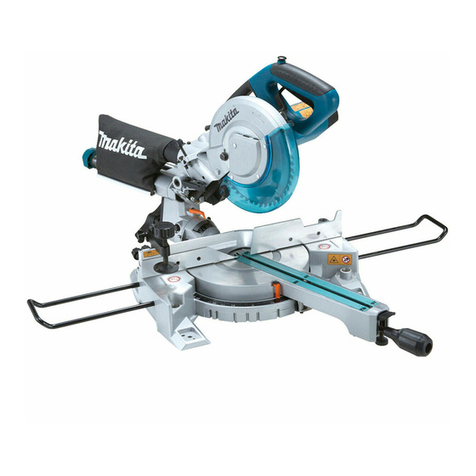
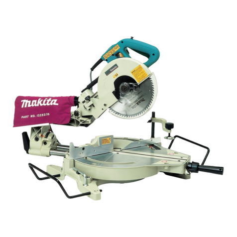
Makita MLS100 User manual

1
GB Compound Miter Saw INSTRUCTION MANUAL
UA Комбінована торцювальна пила ІНСТРУКЦІЯ ЗЕКСПЛУАТАЦІЇ
PL Złożona piła grzbietnica INSTRUKCJA OBSŁUGI
RO
Ferăstrău pentru tăieri oblice combinate
MANUAL DE INSTRUCŢIUNI
DE Kapp- und Gehrungssäge BEDIENUNGSANLEITUNG
HU Kombinált gérvágó HASZNÁLATI KÉZIKÖNYV
SK Zložená píla na zrezávanie NÁVOD NA OBSLUHU
CZ Pokosová pila NÁVOD K OBSLUZE
MLS100

2
1
1 007766
1
2 007772
1
2
3
3 007830
1
4 007754
1
5 007767
1
6 007755
1
7 001782
1
8 007777
1
9 007832
2
1
3
130mm
10 007831
1
2
11 007768
1
12 007763
1
13 007757
12
14 007900
1
15 007761

3
1
2
16 007771
1
17 007774
1
2
18 007770
12
3
4
19 007808
1
23
4
5
6
20 004852
1
21 015064
1
22 007775
1
23 007776
12
24 001549
1
2
4
3
25 015059
1
26 015060 27 015061
1
2
3
4
5
28 001844
1
2
3
29 007760
1
30 007754

4
31 007759
11
32 015062
1
33 015063
1
34 007752
1
2
3
35 010798
1
36 007757
1
2
37 007751 38 007834
1
2
39 007756

5
ENGLISH (Original instructions)
Explanation of general view
1-1. Wrench
2-1. Knob
3-1. Auxiliary plate
3-2. Screw
3-3. Base
4-1. Stopper pin
5-1. Bolt
6-1. Blade guard
7-1. Blade guard
8-1. Kerf board
9-1. Adjusting bolt
10-1. Top surface of turn base
10-2. Periphery of blade
10-3. Guide fence
11-1. Lock lever
11-2. Grip
12-1. Knob
13-1. Pointer
14-1. Lever
14-2. Switch trigger
15-1. Switch trigger
16-1. Wrench
16-2. Center cover
17-1. Hex bolt
18-1. Hex bolt
18-2. Wrench
19-1. Blade case
19-2. Arrow
19-3. Arrow
19-4. Saw blade
20-1. Spindle
20-2. Flange
20-3. Saw blade
20-4. Flange
20-5. Hex bolt
20-6. Ring
21-1. Sub-fence
22-1. Dust bag
23-1. Fastener
24-1. Support
24-2. Turn base
25-1. Vise knob
25-2. Screw
25-3. Vise arm
25-4. Vise rod
26-1. Vertical vise
28-1. Vise
28-2. Spacer block
28-3. Guide fence
28-4. Aluminum extrusion
28-5. Spacer block
29-1. Set plate
29-2. Screw
29-3. Holder
30-1. Stopper pin
32-1. Hex bolt
33-1. Triangular rule
34-1. 0 ゚adjusting bolt
35-1. Triangular rule
35-2. Saw blade
35-3. Top surface of turn base
36-1. Pointer
37-1. 45 ゚bevel angle adjusting bolt
37-2. Pointer
39-1. Brush holder cap
39-2. Screwdriver
SPECIFICATIONS
Model MLS100
Blade diameter 255 mm
Blade body thickness 1.6 mm - 2.4 mm
Hole diameter
For all countries other than European countries 25.4 mm
For European countries 30 mm
Max. Cutting capacities (H x W) with blade 255 mm in diameter
Miter angle
Bevel angle 0° 45° (left and right)
0° 75 mm x 130 mm 75 mm x 90 mm
45° (left) 48 mm x 120 mm 48 mm x 90 mm
No load speed (min-1) 4,200
Dimensions (L x W x H) 610 mm x 485 mm x 515 mm
Net weight 14.7 kg
Safety class /II
• Due to our continuing program of research and development, the specifications herein are subject to change without notice.
• Specifications may differ from country to country.
• Weight according to EPTA-Procedure 01/2003
END217-5
Symbols
The following show the symbols used for the equipment.
Be sure that you understand their meaning before use.
・Read instruction manual.
・DOUBLE INSULATION
・To avoid injury from flying debris, keep
holding the saw head down, after
making cuts, until the blade has come
to a complete stop.
・Do not place hand or fingers close to
the blade.

6
・For your safety, remove the chips,
small pieces, etc. from the table top
before operation.
・Always set SUB-FENCE to left position
when performing left bevel cuts. Failure
to do so may cause serious injury to
operator.
・To loosen the bolt, turn it clockwise.
・Only for EU countries
Do not dispose of electric equipment
together with household waste material!
In observance of the European Directive,
on Waste Electric and Electronic
Equipment and its implementation in
accordance with national law, electric
equipment that have reached the end of
their life must be collected separately
and returned to an environmentally
compatible recycling facility.
ENE004-1
Intended use
The tool is intended for accurate straight and miter
cutting in wood. With appropriate saw blades, aluminum
can also be sawed.
ENF002-2
Power supply
The tool should be connected only to a power supply of
the same voltage as indicated on the nameplate, and
can only be operated on single-phase AC supply. They
are double-insulated and can, therefore, also be used
from sockets without earth wire.
ENG905-1
Noise
The typical A-weighted noise level determined
according to EN61029:
Sound pressure level (LpA) : 92 dB (A)
Sound power level (LWA) : 105 dB (A)
Uncertainty (K) : 3 dB (A)
Wear ear protection
ENH003-15
For European countries only
EC Declaration of Conformity
Makita declares that the following Machine(s):
Designation of Machine:
Compound Miter Saw
Model No./ Type: MLS100
Conforms to the following European Directives:
2006/42/EC
They are manufactured in accordance with the following
standard or standardized documents:
EN61029
The technical file in accordance with 2006/42/EC is
available from:
Makita, Jan-Baptist Vinkstraat 2, 3070, Belgium
30.5.2014
000331
Yasushi Fukaya
Director
Makita, Jan-Baptist Vinkstraat 2, 3070, Belgium
GEA010-1
General Power Tool Safety Warnings
WARNING Read all safety warnings and all
instructions.
Failure to follow the warnings and instructions
may result in electric shock, fire and/or serious injury.
Save all warnings and instructions for
future reference.
ENB034-8
MITER SAW SAFETY WARNINGS
1. Keep hands out of path of saw blade. Avoid
contact with any coasting blade. It can still
cause severe injury.
2. Check the saw blade carefully for cracks or
deformation before operation.
Replace damaged blades immediately.
3. Replace the kerf board when worn.
4. Use only saw blades specified by the
manufacturer which conform to EN847-1.
5. Do not use saw blades manufactured from
high speed steel.
6. Wear eye protection.
7. Wear hearing protection to reduce the risk of
hearing loss.
8. Wear gloves for handling saw blade (saw
blades shall be carried in a holder wherever
practicable) and rough material.
9. Connect miter saws to a dust collecting
device when sawing.
10. Select saw blades in relation to the material to
be cut.
11. Do not use the saw to cut other than wood,
aluminum or similar materials.
12.
Always secure all moving portions before
carrying the tool. When lifting or carrying the
tool, do not use the guard as a carrying handle.
13.
Do not operate saw without guards in place. Check
blade guard for proper closing before each use. Do
not operate saw if blade guard does not move
freely and close instantly. Never clamp or tie the
blade guard into the open position.
14. Keep the floor area free of loose material e.g.
chips and cut-offs.
15. Use only saw blades that are marked with a
maximum speed equal to or higher than the
no load speed marked on the tool.

7
16. When the tool is fitted with a laser or LED, do
not replace the laser or LED with a different
type. Ask an authorized service center for repair.
17. Never remove any cut-offs or other parts of
the workpiece from the cutting area whilst the
tool is running with an unguarded saw blade.
18.
Do not perform any operation freehand.
The
workpiece must be secured firmly against the turn base
and guide fence with the vise during all operations.
Never use your hand to secure the workpiece.
19. Ensure that the tool is stable before each cut.
20. Fix the tool to a work bench, if needed.
21. Support long workpieces with appropriate
additional supports.
22.
Never cut so small workpiece which cannot be
securely held by the vise.
Improperly held workpiece
may cause kickback and serious personal injury.
23. Never reach around saw blade.
24.
Turn off tool and wait for saw blade to stop before
moving workpiece or changing settings.
25.
Unplug tool before changing blade or servicing.
26. Stopper pin which locks the cutter head down
is for carrying and storage purposes only and
not for any cutting operations.
27.
Do not use the tool in the presence of flammable
liquids or gases.
The electrical operation of the tool
could create an explosion and fire when exposed to
flammable liquids or gases.
28. Use only flanges specified for this tool.
29.
Be careful not to damage the arbor, flanges
(especially the installing surface) or bolt. Damage
to these parts could result in blade breakage.
30. Make sure that the turn base is properly
secured so it will not move during operation.
31.
For your safety, remove the chips, small pieces,
etc. from the table top before operation.
32. Avoid cutting nails. Inspect for and remove all
nails from the workpiece before operation.
33. Make sure the shaft lock is released before
the switch is turned on.
34. Be sure that the blade does not contact the
turn base in the lowest position.
35. Hold the handle firmly. Be aware that the saw
moves up or down slightly during start-up and
stopping.
36. Make sure the blade is not contacting the
workpiece before the switch is turned on.
37. Before using the tool on an actual workpiece,
let it run for a while. Watch for vibration or
wobbling that could indicate poor installation
or a poorly balanced blade.
38. Wait until the blade attains full speed before
cutting.
39. Stop operation immediately if you notice
anything abnormal.
40.
Do not attempt to lock the trigger in the on position.
41. Be alert at all times, especially during
repetitive, monotonous operations. Do not be
lulled into a false sense of security. Blades
are extremely unforgiving.
42. Always use accessories recommended in this
manual. Use of improper accessories such as
abrasive wheels may cause an injury.
43. Take care when slotting.
44. Some dust created from operation contains
chemicals known to cause cancer, birth
defects or other reproductive harm. Some
examples of these chemicals are:
• lead from lead-based-painted material and,
•
arsenic and chromium from chemically-
treated lumber.
Your risk from these exposures varies,
depending on how often you do this type of
work. To reduce your exposure to these
chemicals: work in a well ventilated area and
work with approved safety equipment, such
as those dust masks that are specially
designed to filter out microscopic particles.
45. To reduce the emitted noise, always be sure
that the blade is sharp and clean.
46. The operator is adequately trained in the use,
adjustment and operation of the machine.
SAVE THESE INSTRUCTIONS.
WARNING:
DO NOT let comfort or familiarity with product (gained
from repeated use) replace strict adherence to safety
rules for the subject product. MISUSE or failure to
follow the safety rules stated in this instruction manual
may cause serious personal injury.
INSTALLATION
Fig.1
Fig.2
When the tool is shipped, the handle is locked in the
lowered position by the stopper pin. Loosen the bolt with
a wrench provided with the tool and move the saw head
to the right angle. Remove the bolt and secure the saw
head with the knob.
Installing auxiliary plate
Fig.3
Installing the auxiliary plate using the hole in the tool's
base and secure it by tightening the screw.
Bench mounting
When the tool is shipped, the handle is locked in the
lowered position by the stopper pin. Release the stopper pin
by lowering the handle slightly and pulling the stopper pin.
Fig.4
This tool should be bolted with four bolts to a level and
stable surface using the bolt holes provided in the tool's
base. This will help prevent tipping and possible injury.
Fig.5

8
FUNCTIONAL DESCRIPTION
CAUTION:
• Always be sure that the tool is switched off and
unplugged before adjusting or checking function
on the tool.
Blade guard
Fig.6
When lowering the handle, the blade guard rises
automatically. The guard is spring loaded so it returns to
its original position when the cut is completed and the
handle is raised. NEVER DEFEAT OR REMOVE THE
BLADE GUARD OR THE SPRING WHICH ATTACHES
TO THE GUARD.
In the interest of your personal safety, always maintain
the blade guard in good condition. Any irregular
operation of the blade guard should be corrected
immediately. Check to assure spring loaded return
action of guard. NEVER USE THE TOOL IF THE
BLADE GUARD OR SPRING ARE DAMAGED,
FAULTY OR REMOVED. DOING SO IS HIGHLY
DANGEROUS AND CAN CAUSE SERIOUS
PERSONAL INJURY.
If the see-through blade guard becomes dirty, or
sawdust adheres to it in such a way that the blade is no
longer easily visible, unplug the saw and clean the
guard carefully with a damp cloth. Do not use solvents
or any petroleum-based cleaners on the plastic guard.
If the see-through blade guard becomes dirty, or
sawdust adheres to it in such a way that the blade
and/or workpiece is no longer easily visible, unplug the
saw and clean the guard carefully with a damp cloth. Do
not use solvents or any petroleum-based cleaners on
the plastic guard.
If the blade guard is especially dirty and vision through
the guard is impaired, use the supplied wrench to
loosen the hex bolt holding the center cover. Loosen the
hex bolt by turning it counterclockwise and raise the
blade guard and center cover. With the blade guard so
positioned, cleaning can be more completely and
efficiently accomplished. When cleaning is complete,
reverse procedure above and secure bolt. Do not
remove spring holding blade guard. If guard becomes
discolored through age or UV light exposure, contact a
Makita service center for a new guard. DO NOT
DEFEAT OR REMOVE GUARD.
Fig.7
Kerf board
Fig.8
This tool is provided with the kerf board in the turn base
to minimize tearing on the exit side of a cut. If the kerf
groove has not yet been cut in the kerf board by the
factory, you should cut the groove before actually using
the tool to cut a workpiece. Switch on the tool and lower
the blade gently to cut a groove in the kerf board.
Maintaining maximum cutting capacity
This tool is factory adjusted to provide the maximum
cutting capacity for a 255 mm saw blade.
When installing a new blade, always check the lower limit
position of the blade and if necessary, adjust it as follows:
First, unplug the tool. Lower the handle completely. Use
the wrench to turn the adjusting bolt until the periphery
of the blade extends slightly below the top surface of the
turn base at the point where the front face of the guide
fence meets the top surface of the turn base.
Fig.9
With the tool unplugged, rotate the blade by hand while
holding the handle all the way down to be sure that the
blade does not contact any part of the lower base. Re-
adjust slightly, if necessary.
Fig.10
CAUTION:
• After installing a new blade, always be sure that
the blade does not contact any part of the lower
base when the handle is lowered completely.
Always do this with the tool unplugged.
Adjusting the miter angle
Fig.11
Loosen the grip by turning counterclockwise. Turn the
turn base while pressing down the lock lever. When you
have moved the grip to the position where the pointer
points to the desired angle on the miter scale, securely
tighten the grip clockwise.
CAUTION:
• When turning the turn base, be sure to raise the
handle fully.
• After changing the miter angle, always secure the
turn base by tightening the grip firmly.
Adjusting the bevel angle
Fig.12
Fig.13
To adjust the bevel angle, loosen the knob at the rear of
the tool counterclockwise.
Push the handle to the left to tilt the saw blade until the
pointer points to the desired angle on the bevel scale.
Then tighten the knob clockwise firmly to secure the arm.
CAUTION:
• When tilting the saw blade, be sure to raise the
handle fully.
• After changing the bevel angle, always secure the
arm by tightening the knob clockwise.
Switch action
CAUTION:
• Before plugging in the tool, always check to see
that the switch trigger actuates properly and
returns to the "OFF" position when released.

9
For European countries
Fig.14
To start the tool, push the lever to the right and then pull
the switch trigger. Release the switch trigger to stop.
For all countries other than European countries
Fig.15
To start the tool, simply pull the switch trigger. Release
the switch trigger to stop.
WARNING:
• NEVER use tool without a fully operative switch
trigger. Any tool with an inoperative switch is
HIGHLY DANGEROUS and must be repaired
before further usage.
ASSEMBLY
CAUTION:
• Always be sure that the tool is switched off and
unplugged before carrying out any work on the
tool.
Installing or removing saw blade
CAUTION:
• Always be sure that the tool is switched off and
unplugged before installing or removing the blade.
• Use only the Makita wrench provided to install or
remove the blade. Failure to do so may result in
overtightening or insufficient tightening of the hex
bolt. This could cause an injury.
When removing or installing the blade, keep the handle
in the raised position.
Fig.16
To remove the blade, use the wrench to loosen the hex
bolt holding the center cover by turning it counterclockwise.
Raise the blade guard and center cover.
Fig.17
Press the shaft lock to lock the spindle and use the
wrench to loosen the hex bolt clockwise. Then remove
the hex bolt, outer flange and blade.
Fig.18
To install the blade, mount it carefully onto the spindle,
making sure that the direction of the arrow on the
surface of the blade matches the direction of the arrow
on the blade case. Install the outer flange and hex bolt,
and then use the wrench to tighten the hex bolt (left-
handed) securely counterclockwise while pressing the
shaft lock.
Fig.19
Fig.20
CAUTION:
• The ring 25.4 mm or 30 mm in outer diameter is
factory-installed onto the spindle. Before mounting
the blade onto the spindle, always be sure that the
correct ring for the arbor hole of the blade you
intend to use is installed onto the spindle.
Install the outer flange and hex bolt, and then use the
wrench to tighten the hex bolt (left-handed) securely
counterclockwise while pressing the shaft lock.
Return the blade guard and center cover to its original
position. Then tighten the hex bolt clockwise to secure
the center cover. Lower the handle to make sure that
the blade guard moves properly. Make sure shaft lock
has released spindle before making cut.
Sub-fence (for European countries only)
Fig.21
This tool is equipped with the sub-fence. Usually
position the sub-fence inside. However, when
performing left bevel cuts, flip it outward.
CAUTION:
• When performing left bevel cuts, flip the sub-fence
outward. Otherwise, it will contact the blade or a
part of the tool, causing possible serious injury to
the operator.
Dust bag
Fig.22
Fig.23
The use of the dust bag makes cutting operations clean
and dust collection easy. To attach the dust bag, fit it
onto the dust nozzle.
When the dust bag is about half full, remove the dust
bag from the tool and pull the fastener out. Empty the
dust bag of its contents, tapping it lightly so as to
remove particles adhering to the insides which might
hamper further collection.
NOTE:
If you connect a Makita vacuum cleaner to your saw,
more efficient and cleaner operations can be performed.
Securing workpiece
WARNING:
• It is extremely important to always secure the
workpiece properly and tightly with the vise.
Failure to do so can cause the tool to be damaged
and/or the workpiece to be destroyed. PERSONAL
INJURY MAY ALSO RESULT. Also, after a cutting
operation, DO NOT raise the blade until the blade
has come to a complete stop.
CAUTION:
• When cutting long workpieces, use supports that
are as high as the top surface level of the turn
base. Do not rely solely on the vertical vise and/or
horizontal vise to secure the workpiece.
Thin material tends to sag. Support workpiece
over its entire length to avoid blade pinch and
possible KICKBACK.
Fig.24

10
Vertical vise
Fig.25
The vertical vise can be installed in two positions on
either the left or right side of the guide fence. Insert the
vise rod into the hole in the guide fence and tighten the
screw to secure the vise rod.
Position the vise arm according to the thickness and
shape of the workpiece and secure the vise arm by
tightening the screw. Make sure that no part of the tool
contacts the vise when lowering the handle all the way.
If some part contacts the vise, re-position the vise.
Press the workpiece flat against the guide fence and the
turn base. Position the workpiece at the desired cutting
position and secure it firmly by tightening the vise knob.
CAUTION:
• The workpiece must be secured firmly against the
turn base and guide fence with the vise during all
operations.
OPERATION
010852
CAUTION:
• Before use, be sure to release the handle from the
lowered position by pulling the stopper pin.
• Make sure the blade is not contacting the
workpiece, etc. before the switch is turned on.
• Do not apply excessive pressure on the handle
when cutting. Too much force may result in
overload of the motor and/or decreased cutting
efficiency. Push down handle with only as much
force as is necessary for smooth cutting and
without significant decrease in blade speed.
• Gently press down the handle to perform the cut. If
the handle is pressed down with force or if lateral
force is applied, the blade will vibrate and leave a
mark (saw mark) in the workpiece and the
precision of the cut will be impaired.
1. Press cutting
Fig.26
Secure the workpiece with the vise. Switch on the tool
without the blade making any contact and wait until
the blade attains full speed before lowering. Then
gently lower the handle to the fully lowered position to
cut the workpiece. When the cut is completed, switch
off the tool and WAIT UNTIL THE BLADE HAS COME
TO A COMPLETE STOP before returning the blade to
its fully elevated position.
2. Miter cutting
Refer to the previously covered "Adjusting the
miter angle".
3. Bevel cut
Fig.27
Loosen the knob and tilt the saw blade to set the
bevel angle (Refer to the previously covered
"Adjusting the bevel angle"). Be sure to retighten
the knob firmly to secure the selected bevel angle
safely. Secure the workpiece with a vise. Switch
on the tool without the blade making any contact
and wait until the blade attains full speed. Then
gently lower the handle to the fully lowered
position while applying pressure in parallel with the
blade. When the cut is completed, switch off the
tool and WAIT UNTIL THE BLADE HAS COME TO
A COMPLETE STOP before returning the blade to
its fully elevated position.
CAUTION:
• Always be sure that the blade will move down to
bevel direction during a bevel cut. Keep hands out
of path of saw blade.
• During a bevel cut, it may create a condition
whereby the piece cut off will come to rest against
the side of the blade. If the blade is raised while
the blade is still rotating, this piece may be caught
by the blade, causing fragments to be scattered
which is dangerous. The blade should be raised
ONLY after the blade has come to a complete stop.
• When pressing the handle down, apply pressure
parallel to the blade. If the pressure is not parallel
to the blade during a cut, the angle of the blade
might be shifted and the precision of the cut will be
impaired.
• (Only for European countries) always set the sub-
fence outside when performing left bevel cuts.
4. Compound cutting
Compound cutting is the process in which a bevel
angle is made at the same time in which a miter
angle is being cut on a workpiece. Compound
cutting can be performed at angle shown in the
table.
Miter angle
Bevel angle
Left and Right 0 - 45
45
006366
When performing compound cutting, refer to
"Press cutting", "Miter cutting" and "Bevel cut"
explanations.

11
5. Cutting aluminum extrusion
Fig.28
When securing aluminum extrusions, use spacer
blocks or pieces of scrap as shown in the figure to
prevent deformation of the aluminum. Use a
cutting lubricant when cutting the aluminum
extrusion to prevent build-up of the aluminum
material on the blade.
CAUTION:
• Never attempt to cut thick or round aluminum
extrusions. Thick aluminum extrusions may come
loose during operation and round aluminum
extrusions cannot be secured firmly with this tool.
6. Wood facing
Use of wood facing helps to assure splinter-free
cuts in workpieces. Attach a wood facing to the
guide fence using the holes in the guide fence.
See the figure concerning the dimensions for a
suggested wood facing.
Over 10mm Over 460mm
11
25mm
100mm 115mm 100mm115mm
007833
CAUTION:
• Use straight wood of even thickness as the wood
facing.
•
Use screws to attach the wood facing to the guide
fence. The screws should be installed so that the
screw heads are below the surface of the wood facing.
• When the wood facing is attached, do not turn the
turn base with the handle lowered. The blade
and/or the wood facing will be damaged.
• The maximum cutting width will be smaller by the
width of wood facing.
7. Cutting repetitive lengths
Fig.29
When cutting several pieces of stock to the same
length, ranging from 240 mm to 380 mm, use of
the set plate (optional accessory) will facilitate
more efficient operation. Install the set plate on the
holder (optional accessory) as shown in the figure.
Align the cutting line on your workpiece with either
the left or right side of the groove in the kerf board,
and while holding the workpiece from moving,
move the set plate flush against the end of the
workpiece. Then secure the set plate with the
screw. When the set plate is not used, loosen the
screw and turn the set plate out of the way.
Carrying tool
Fig.30
Make sure that the tool is unplugged. Secure the blade
at 0° bevel angle and the turn base at left miter angle
fully. Lower the handle fully and lock it in the lowered
position by pushing in the stopper pin.
Carry the tool by carrying grip as shown in the figure. If
you remove the holders, dust bag, etc., you can carry
the tool more easily.
Fig.31
CAUTION:
• Always secure all moving portions before carrying
the tool.
• Stopper pin is for carrying and storage purposes
only and not for any cutting operations.
MAINTENANCE
CAUTION:
• Always be sure that the tool is switched off and
unplugged before attempting to perform inspection
or maintenance.
• Never use gasoline, benzine, thinner, alcohol or
the like. Discoloration, deformation or cracks may
result.
WARNING:
• Always be sure that the blade is sharp and clean
for the best and safest performance.
Adjusting the cutting angle
This tool is carefully adjusted and aligned at the factory,
but rough handling may have affected the alignment. If
your tool is not aligned properly, perform the following:
1. Miter angle
Fig.32
Loosen the grip which secures the turn base. Turn
the turn base so that the pointer points to 0° on the
miter scale. Tighten the grip and loosen the hex
bolts securing the guide fence using the wrench. If
the pointer does not point to 0° on the miter scale,
loosen the screw which secures the pointer and
move and secure the pointer plate so that the
pointer points to 0° on the miter scale.
Lower the handle fully and lock it in the lowered
position by pushing in the stopper pin. Square the
side of the blade with the face of the guide fence
using a triangular rule, try-square, etc. Then
securely tighten the hex bolts on the guide fence
in the order from the right side.
Fig.33
1. Hole

12
2. Bevel angle
(1) 0° bevel angle
Fig.34
Lower the handle fully and lock it in the
lowered position by pushing in the stopper
pin. Loosen the knob at the rear of the tool.
Loosen the hex nut and turn the 0° bevel
angle adjusting bolt on the right side of the
turn base two or three revolutions clockwise
to tilt the blade to the right.
Carefully square the side of the blade with
the top surface of the turn base using the
triangular rule, try-square, etc. by turning the
0° bevel angle adjusting bolt
counterclockwise. Then tighten the hex nut to
secure the 0° bevel angle adjusting bolt and
tighten the knob securely.
Make sure that the pointer on the arm points
to 0° on the bevel scale. If it does not point to
0° on the bevel scale, loosen the screw
which secures the pointer and move and
secure the pointer plate so that the pointer
points to 0° on the bevel scale.
Fig.35
Fig.36
(2) 45° bevel angle
Fig.37
Adjust the 45° bevel angle only after
performing 0° bevel angle adjustment. To
adjust left 45° bevel angle, loosen the knob
and tilt the blade to the left fully. Make sure
that the pointer on the arm points to 45° on
the bevel scale on the arm. If the pointer
does not point to 45°, turn the 45° bevel
angle adjusting bolt on the left side of the
arm until the pointer points to 45°.
Replacing carbon brushes
Fig.38
Remove and check the carbon brushes regularly.
Replace when they wear down to 3 mm in length. Keep
the carbon brushes clean and free to slip in the holders.
Both carbon brushes should be replaced at the same
time. Use only identical carbon brushes.
Use a screwdriver to remove the brush holder caps.
Take out the worn carbon brushes, insert the new ones
and secure the brush holder caps.
Fig.39
After use
• After use, wipe off chips and dust adhering to the
tool with a cloth or the like. Keep the blade guard
clean according to the directions in the previously
covered section titled "Blade guard". Lubricate the
sliding portions with machine oil to prevent rust.
To maintain product SAFETY and RELIABILITY, repairs,
any other maintenance or adjustment should be
performed by Makita Authorized Service Centers,
always using Makita replacement parts.

13
УКРАЇНСЬКА (Оригінальні інструкції)
Пояснення до загального виду
1-1. Ключ
2-1. Ручка
3-1. Допоміжна пластина
3-2. Гвинт
3-3. Станина
4-1. Стопорна шпилька
5-1. Болт
6-1. Кожух полотна
7-1. Кожух полотна
8-1. Щиток зпропилом
9-1. Болт регулювання
10-1. Верхня поверхня поворотної
основи
10-2. Контур диску
10-3. Напрямна планка
11-1. Стопорний важіль
11-2. Затиск
12-1. Ручка
13-1. Покажчик
14-1. Важіль
14-2. Кнопка вимикача
15-1. Кнопка вимикача
16-1. Ключ
16-2. Центральна кришка
17-1. Болт із шестигранною голівкою
18-1. Болт із шестигранною голівкою
18-2. Ключ
19-1. Корпус диску
19-2. Стрілка
19-3. Стрілка
19-4. Диск пили
20-1. Шпиндель
20-2. Фланець
20-3. Диск пили
20-4. Фланець
20-5. Болт із шестигранною голівкою
20-6. Кільце
21-1. Напрямна підпора
22-1. Мішок для пилу
23-1. Кріплення
24-1. Опора
24-2. Поворотна основа
25-1. Затискна ручка
25-2. Гвинт
25-3. Затискне плече
25-4. Затискний штифт
26-1. Вертикальний затиск
28-1. Лещата
28-2. Розділювальний блок
28-3. Напрямна планка
28-4. Алюмінієвий профіль
28-5. Розділювальний блок
29-1. Наборна пластина
29-2. Гвинт
29-3. Тримач
30-1. Стопорна шпилька
32-1. Болт із шестигранною голівкою
33-1. Трикутна лінійка
34-1. Болт регулювання 0 ゚
35-1. Трикутна лінійка
35-2. Диск пили
35-3. Верхня поверхня поворотної
основи
36-1. Покажчик
37-1. Болт регулювання кута нахилу
45 ゚
37-2. Покажчик
39-1. Ковпачок щіткотримача
39-2. Викрутка
ТЕХНІЧНІ ХАРАКТЕРИСТИКИ
Модель MLS100
Діаметр диску 255 мм
Товщина диска 1,6 мм - 2,4 мм
Діаметр отвору
Для всіх країн крім Європейських 25,4 мм
Для Європейських країн 30 мм
Макс. ріжуча спроможність (ВхШ) здіаметром диска 255 мм
Косий кут
Кут нахилу 0° 45° (лівий та правий)
0° 75 мм x 130 мм 75 мм x 90 мм
45° (лівий) 48 мм x 120 мм 48 мм x 90 мм
Швидкість без навантаження (хв-1) 4200
Розміри (ДхШхВ) 610 мм x 485 мм x 515 мм
Чиста вага 14,7 кг
Клас безпеки /II
• Через те, що ми не припиняємо програми досліджень ірозвитку, наведені тут технічні характеристики можуть бути змінені
без попередження.
• Урізних країнах технічні характеристики можуть бути різними.
• Вага відповідно до EPTA-Procedure 01/2003
END217-5
Символи
Далі наведені символи, які застосовуються для
позначення обладнання. Перед користуванням
переконайтеся, що Ви розумієте їхнє значення.
・Прочитайте дану інструкцію.
・ПОДВІЙНА ІЗОЛЯЦІЯ

14
・Для того, щоб запобігти поранення
унаслідок розлітання сміття, слід
притиснути голівку пили, після
різання, доки диск повністю не
зупиниться.
・Тримай руки або пальці на відстані
від диску.
・Перед початком роботи заберіть
тирсу, маленькі частки іт.д. зі столу
для вашої безпеки.
・Під час виконання прорізів злівим
нахилом, завжди слід встановлювати
НАПРЯМНУ ПІДПОРУ вліве
положення. Невиконання цієї умови
може призвести до серйозного
поранення оператора.
・Для того, щоб відпустити болт
поверніть його за годинниковою
стрілкою.
・Тільки для країн ЄС
Не викидайте електроприлади разом
із побутовим сміттям!
Згідно зЄвропейською директивою
про утилізацію електричного та
електронного обладнання ізїї
використанням із дотриманням
національних законів, електричне
обладнання, термін служби якого
закінчився, слід збирати вокремо
відведених місцях іповертати на
відповідні підприємства зйого
переробки.
ENE004-1
Призначення
Інструмент призначено для точного різання
деревини за прямою лінією та під кутом. Якщо
встановити відповідні пильні диски, можна також
різати алюміній.
ENF002-2
Джерело живлення
Інструмент можна підключати лише до джерела
живлення, що має напругу, зазначену втабличці із
заводськими характеристиками, івін може
працювати лише від однофазного джерела змінного
струму. Він має подвійну ізоляцію, аотже може також
підключатися до розеток без лінії заземлення.
ENG905-1
Шум
Рівень шуму за шкалою Аутиповому виконанні,
визначений відповідно до EN61029:
Рівень звукового тиску (LpA): 92 дБ (A)
Рівень звукової потужності (LWA): 105 дБ (A)
Похибка (K): 3 дБ (A)
Користуйтеся засобами захисту слуху
ENH003-15
Тільки для країн Європи
Декларація про відповідність стандартам
ЄС
Компанія Makita наголошує на тому, що
обладнання:
Позначення обладнання:
Комбінована торцювальна пила
№моделі / тип: MLS100
Відповідає таким Європейським Директивам:
2006/42/EC
Обладнання виготовлене відповідно до таких
стандартів або стандартизованих документів:
EN61029
Технічну інформацію відповідно до 2006/42/EC
можна отримати:
Makita, Jan-Baptist Vinkstraat 2, 3070, Бельгія
30.5.2014
000331
Ясуші Фукайя
Директор
Makita, Jan-Baptist Vinkstraat 2, 3070, Бельгія
GEA010-1
Застереження стосовно техніки
безпеки при роботі з
електроприладами
УВАГА! Прочитайте усі застереження
стосовно техніки безпеки та всі інструкції.
Недотримання даних застережень та інструкцій
може призвести до ураження струмом та виникнення
пожежі та/або серйозних травм.
Збережіть усі інструкції зтехніки
безпеки та експлуатації на майбутнє.
ENB034-8
ПОПЕРЕДЖЕННЯ ПРО
НЕОБХІДНУ ОБЕРЕЖНІСТЬ ПІД
ЧАС РОБОТИ З
ТОРЦЮВАЛЬНОЮ ПИЛОЮ
1. Не торкайтесь руками доріжки диска пилки.
Не слід торкатися диску що рухається за
інерцією. Він усе ще може завдати
серйозної травми.
2. Перед початком роботи ретельно
перевіряйте диск пилки на наявність
тріщин або деформацій.
Негайно замінюйте пошкоджені диски.

15
3. Слід замінити щиток із пропилом уразі
його спрацювання.
4. Використовуйте тільки рекомендовані
виробником диски пилки, які відповідають
стандарту EN847-1.
5. Не слід застосовувати диски пилки, що
виготовлені зшвидкорізальної сталі.
6. Одягайте захисні окуляри.
7. Надягайте засоби захисту органів слуху,
щоб знизити ризик втрати слуху.
8. Надягайте рукавиці під час роботи здиском
пилки (диски пилки по можливості слід
переносити утримачі) та грубими
матеріалами.
9. Під час різання слід приєднати пристрій
для збору пилу до пили.
10. Обирайте диски пили відповідно до
матеріалу, що буде різатися.
11. Пилу слід застосовувати тільки для різання
деревини, алюмінію або подібних
матеріалів.
12. Перед перенесенням інструмента завжди
закріплюйте всі рухомі деталі. При
підніманні або перенесенні інструмента не
використовуйте захисний кожух як
переносну ручку.
13. Не слід експлуатувати пилку, якщо
захисний кожух не встановлено вробочому
положенні. Щораз перед початком роботи
слід перевіряти належне закриття кожуху.
Не слід починати роботу, якщо захисний
кожух диску не рухається вільно та одразу
не закривається. Ніколи не слід
затискувати або блокувати захисний кожух
диску увідкритому положенні.
14. Слідкуйте за тим, щоб на підлозі не було
сипких матеріалів, наприклад тирси та
обрізків.
15. Використовуйте тільки такі диски пилки, на
яких вказана максимальна швидкість
дорівнює зазначеній на інструменті
швидкості холостого ходу або єбільшою за
неї.
16. Коли інструмент оснащений лазером або
світлодіодом, не замінюйте лазер або
світлодіод елементами іншого типу.
Звертайтеся до авторизованого сервісного
центру для проведення ремонту.
17. Ніколи не видаляйте обрізки або інші
частини оброблюваної деталі ззони
різання, коли інструмент працює без
захисного кожуха на диску пилки.
18. Не слід виконувати різання від руки.Під час
експлуатації деталь слід міцно кріпити до
поворотної основи та напрямної планки за
допомогою лещат. Ніколи не утримуй деталь
руками.
19. Перед кожним різанням перевіряйте, щоб
інструмент був стійким.
20. Якщо потрібно, прикріпіть інструмент до
верстака.
21. Підтримуйте довгі деталі відповідними
додатковими опорами.
22. Ніколи не пиляйте такі маленькі деталі, які
неможливо надійно закріпити лещатами.
Неналежним чином закріплена деталь може
спричинити віддачу, що призведе до
отримання серйозних травм.
23. Ніколи не обхоплюй диск пилки.
24. Для того, щоб пересунути деталь або
змінити настройки, вимкніть інструмент та
заждіть доки диск пилки не зупиниться.
25. Для зміни диску або здійснення технічного
обслуговування відключить інструмент від
мережі.
26. Стопорна шпилька, яка блокує ріжучу
голівку призначена тільки для
транспортування та зберігання, ане для
різання.
27. Не можна використовувати інструмент за
наявності поруч вогненебезпечної рідини
або газів.Контакт інструмента, який
знаходиться під напругою, звогненебезпечною
рідиною або газами може спричинити вибух
або пожежу.
28. Слід застосовувати тільки фланці зазначені
для цього інструменту.
29. Будьте обережними, щоб не пошкодити
провідний вал, фланці (особливо поверхню
встановлення) або болт. Пошкодження цих
частин може призвести до поломки диску.
30. Поворотна основа повинна бути надійно
закріплена, щоб не рухалась під час роботи.
31. Перед початком роботи заберіть стружку,
маленькі частини іт.д. зі столу для вашої
безпеки.
32. Слід уникати різання цвяхів. Перед
початком роботи огляньте та заберіть усі
цвяхи здеталі.
33. Перед увімкненням перевірте, щоб
фіксатор вала було відпущено.
34. Диск не повинен торкатись поворотної
основи внайнижчому положенні.
35. Слід міцно триматись за ручку. Пам'ятайте,
що пила мимовільно пересувається вгору
та вниз під час пуску та зупинки.
36. Перевірте, щоб полотно не торкалося
деталі до його увімкнення.
37. Перед використанням інструменту на
фактичній деталі, залиште його якийсь час
на холостому ході. Зверніть увагу на
вібрацію та колихання, що вказують на
погане встановлення або балансування
диску.

16
38. Заждіть, доки диск набере повну швидкість
до початку різання.
39. Негайно зупинить інструмент якщо вам
здалося щось ненормальне вроботі пили.
40. Не намагайтеся заблокувати курок в
положенні ВМК.
41. Будьте пильними увесь час, особливо під
час виконання повторюваних, монотонних
дії. Не заспокоюйтесь помилковим
почуттям безпеки. Диски нехлюйства не
вибачають.
42. Завжди використовуйте приналежності
рекомендовані вцій інструкції.
Використання неналежного приладдя,
наприклад шліфувальних кіл, може
спричинити травму.
43. Будьте уважними під час різання пазів.
44. Інколи пил, що утворюється під час різання,
містить хімічні речовини, які спричиняють
захворювання на рак, пороки розвитку або
інші репродуктивні шкоди. Нижче наведені
деякі зцих хімічних речовин:
• свинець, який утворюється під час
різання матеріалу збарвником на
свинцевій основі, атакож,
• миш'як та хром, які утворюються під час
різання хімічно обробленого
пиломатеріалу.
Ризик впливу таких речовин залежить
від частоти виконання вами такого виду
роботи. Для того, щоб зменшити вплив
таких хімічних речовин: слід працювати
вдобре провітрюваному приміщенні та
із затвердженими засобами
індивідуального захисту, такими як
пилозахисні маски, які спеціально
призначені для фільтрації
мікроскопічних часток.
45. Для того, щоб зменшити вироблений шум,
диск повинен бути завжди гострим та
чистим.
46. Оператор повинен мати належні знання
щодо користування, регулювання та
експлуатації машини.
ЗБЕРІГАЙТЕ ЦІ ВКАЗІВКИ.
УВАГА:
НІКОЛИ НЕ СЛІД втрачати пильності та
розслаблюватися під час користування виробом
(що трапляється при частому використанні); слід
завжди строго дотримуватися правил безпеки
під час використання цього пристрою.
НЕНАЛЕЖНЕ ВИКОРИСТАННЯ або недотримання
правил безпеки, викладених вцьому документі,
може призвести до серйозних травм.
ВСТАНОВЛЕННЯ
мал.1
мал.2
Під час транспортування інструменту ручку
заблоковано внижньому положенні стопорною
шпилькою. Відпустіть болт за допомогою ключа, який
постачається разом зінструментом, та перемістіть у
правий кут. Зніміть болт та закріпіть ріжучу голівку
пили за допомогою важеля.
Встановлення допоміжної пластини
мал.3
Встановіть допоміжну пластину за допомогою отвору
на основі інструмента та закріпіть її, затягнувши гвинт.
Встановлення на верстат
Під час транспортування інструменту, ручку
заблоковано внижньому положенні стопорною
шпилькою. Відпустіть стопорну шпильку, злегка
опустивши ручку та натиснувши на стопорну шпильку.
мал.4
Цей інструмент слід закріпити чотирма болтами до
рівної та стійкої поверхні через болтові отвори які єв
основі інструменту. Це допоможе уникнути
перекидання та можливого нещасного випадку.
мал.5
ІНСТРУКЦІЯ ЗВИКОРИСТАННЯ
ОБЕРЕЖНО:
• Перед регулюванням та перевіркою справності
інструменту, переконайтеся втому, що він
вимкнений та відключений від мережі.
Захисний кожух диску
мал.6
Коли ви опускаєте ручку, захисний кожух диска
автоматично підіймається. Кожух підпружинений, тому він
повертається упочаткове положення після завершення
різання та підйому ручки. ЗАБОРОНЯЄТЬСЯ
УШКОДЖУВАТИ АБО ЗНІМАТИ ЗАХИСНИЙ КОЖУХ
ДИСКУ АБО ПРУЖИНУ ПРИКРІПЛЕНУ ДО НЬОГО.
Вінтересах вашої безпеки завжди підтримуйте
захисний кожух диска удоброму стані. При
неправильному функціонуванні захисного кожуха диска,
слід негайно налагодити його. Перевіряйте зворотну
дію підпружиненого захисного кожуха.
ЗАБОРОНЯЄТЬСЯ КОРИСТОВАТИСЯ ІНТРУМЕНТОМ
ПРИ НАЯВНОСТІ ПОШКОДЖЕННЯ, НЕІСПРАВНОСТІ
ЗАХИСНОГО КОЖУХА АБО ПРУЖИНИ, АБО ЯКЩО
ВОНИ ЗНЯТІ. НЕВИКОНАННЯ ЦІЄЇ УМОВИ ЄДУЖЕ
НЕБЕЗПЕЧНИМ ТА МОЖЕ ПРИЗВЕСТИ ДО
НЕЩАСНОГО ВИПАДКУ.
Якщо прозорий захисний кожух диска забруднився або
весь покрився тирсою так, що диск погано видно, слід
виключити пилу із мережі та ретельно почистити кожух

17
мокрою ганчіркою. Забороняється застосовувати
розчинники або будь-які миючи засоби на нафтовій
основі для чистки пластмасового захисного кожуха.
Якщо прозорий захисний кожух диска забруднився
або весь покрився тирсою так, що диск та/або
деталь погано видно, слід виключити пилу із мережі
та ретельно почистити кожух мокрою ганчіркою.
Забороняється застосовувати розчинники або будь-
які миючи засоби на нафтовій основі для чистки
пластмасового захисного кожуха.
Якщо захисний кожух диска особливо забруднений та
погіршена видимість через кожух, за допомогою ключа
відпустіть болт із шестигранною голівкою, утримуючий
центральну кришку. Відпустіть болт із шестигранною
голівкою, повертаючи його проти годинникової стрілки
та підніміть захисний кожух диска та центральну
кришку. Уцьому положенні захисний кожух можна
почистити повністю та ретельніше. Після завершення
чистки виконайте вищезазначену процедуру у
зворотному порядку та закріпіть болт. Не знімайте
пружину, яка утримує захисний кожух диска. Уразі
знебарвлення захисного кожуха через тривалу
експлуатацію або внаслідок впливу ультрафіолетового
випромінювання зверніться до центру обслуговування
Makita за новим захисним кожухом.
ЗАБОРОНЯЄТЬСЯ ПОШКОДЖУВАТИ АБО ЗНІМАТИ
ЗАХИСНИЙ КОЖУХ.
мал.7
Щиток зпропилом
мал.8
Цей інструмент забезпечено щитком із пропилом на
поворотній основі для того, щоб мінімізувати розрив
краю пропилу деталі. Якщо паз не було прорізано на
щитку пропилу на заводі, слід прорізати паз перед
фактичним застосуванням інструменту за його
призначенням. Увімкніть інструмент та злегка
опустіть диск, щоб прорізати паз на щитку пропилу.
Утримання максимальної ріжучої
спроможності
Цей інструмент відрегульовано на заводі для
забезпечення максимальної ріжучої спроможності
для диска 255 мм.
Коли ви встановлюєте новий диск, завжди
перевіряйте нижнє граничне положення диску, та
якщо необхідно відрегулюйте його.
Спочатку відключіть інструмент від мережі. Повністю
опустіть ручку. Повертайте регулюючий болт за
допомогою ключа, доки зовнішній край диска не
опуститься трохи нижче верхньої поверхні
поворотної основи втому місці, де лицьова поверхня
напрямної планки зустрічається зверхньою
поверхнею поворотної основи.
мал.9
Коли інструмент вимкнено із мережі, обертайте диск
рукою, перевіряючи, чи не торкається він нижньої
основи, при цьому ручку слід постійно утримувати в
нижньому положенні. Якщо необхідно, повторіть
регулювання ще раз.
мал.10
ОБЕРЕЖНО:
• Після встановлення нового диску, обов'язково
перевірте диск на можливість його торкання
будь-якої частини нижньої основи, при цьому
ручка повинна бути всамому низькому
положенні. Перевірку слід здійснювати, коли
інструмент вимкнено із мережі.
Порядок регулювання косого кута
мал.11
Відпустіть затиск, повернувши його проти стрілки
годинника. Обертайте поворотну основу, натиснувши
на важіль блокування. Коли ви встановите
положення затиску, уякому покажчик співпаде з
бажаним кутом на кутовій шкалі, міцно затягніть
затиск за стрілкою годинника.
ОБЕРЕЖНО:
• Обов'язково підійміть ручку до упору при
обертанні поворотної основи.
• Після зміни косого куту, обов'язково закріпіть
поворотну основу, міцно затягнувши затиск.
Регулювання кута нахилу
мал.12
мал.13
Для того щоб відрегулювати кут нахилу, поверніть
важіль позаду інструмента проти годинникової
стрілки.
Натисніть ручку вліво для того, щоб нахилити диск
пилки, доки покажчик не співпаде збажаним кутом
на шкалі кута нахилу диска. Потім міцно затягніть
важіль за годинниковою стрілкою , щоб закріпити
плече.
ОБЕРЕЖНО:
• Перевірте, щоб ручка була піднята до упору при
нахиленні диска пилки.
• Після зміни кута нахилу обов’язково закріпіть
плече, затягнувши важіль за годинниковою
стрілкою.
Дія вимикача
ОБЕРЕЖНО:
• Перед вмиканням інструменту умережу
обов'язково перевірте, чи кнопка вимикача
нормально спрацьовує іпісля відпускання
повертається вположення "вимкнено".
Для Європейських країн
мал.14
Для того щоб запустити інструмент, пересуньте
важіль праворуч та натисніть на курковий вмикач.

18
Для зупинення роботи курковий вмикач слід
відпустити.
Для всіх країн крім Європейських
мал.15
Для того, щоб запустити інструмент, слід просто
натиснути на курок вмикача. Для зупинення роботи
курок слід відпустити.
УВАГА:
• ЗАБОРОНЯЄТЬСЯ користуватися інструментом,
якщо курок вмикача функціонує не повною
мірою. Будь-який прилад, який має несправний
вмикач, єдуже небезпечним та його слід здати
времонт перед подальшим використанням.
КОМПЛЕКТУВАННЯ
ОБЕРЕЖНО:
• Перед тим, як щось встановлювати на
інструмент, переконайтеся втому, що він
вимкнений та відключений від мережі.
Встановлення та зняття полотна пили
ОБЕРЕЖНО:
• Завжди перевіряйте, щоб верстат був
вимкнений та відключений від сіті перед
встановленням або зняттям полотна.
•
Для встановлення або зняття полотна слід
використовувати тільки ключ виробництва компанії
Makita, що додається. Якщо цю вимогу не виконати,
то болт із шестигранною голівкою може бути
затягнутий або занадто сильно, або недостатньо
сильно. Це може призвести до поранень.
Під час зняття або встановлення диска тримайте
ручку впіднятому положенні.
мал.16
Для того щоб зняти диск, відпустіть болт із
шестигранною голівкою, який утримує центральну
кришку, повертаючи його проти годинникової стрілки
за допомогою ключа. Підніміть захисний кожух диска
та центральну кришку.
мал.17
Натисніть на фіксатор валу для блокування
шпинделя та за допомогою ключа відпустіть болт із
шестигранною голівкою за годинниковою стрілкою.
Потім слід вийняти болт із шестигранною голівкою,
зовнішній фланець та диск.
мал.18
Для того щоб встановити диск, обережно вставте
його на шпиндель, перевіривши, чи співпадає
напрямок стрілки на поверхні диска знапрямком
стрілки на корпусі. Вставте зовнішній фланець та
болт із шестигранною голівкою, потім за допомогою
ключа надійно затягніть болт (лівий) проти
годинникової стрілки, натискаючи на фіксатор валу.
мал.19
мал.20
ОБЕРЕЖНО:
• Вставка із зовнішнім діаметром 25,4 мм або 30
мм встановлена на шпиндель на заводі. Перед
встановленням полотна на шпиндель слід
завжди перевіряти, щоб на шпиндель
встановлювалось кільце під отвір для
шпинделя на полотні відповідного розміру.
Вставте зовнішній фланець та болт із шестигранною
голівкою, потім за допомогою ключа надійно
затягніть болт (лівий) проти годинникової стрілки,
натискаючи на фіксатор валу.
Вставте знову захисний кожух Ата центральну
кришку впочаткове положення. Потім затягніть болт
із шестигранною голівкою, повертаючи за стрілкою
годинника, щоб закріпити центральну кришку.
Опустіть ручку для того, щоб перевірити, що нижні
захисні кожухи пересуваються належним чином.
Перевіряйте, щоб фіксатор валу відпустив шпиндель
перед початком різання.
Нижній щиток
(тільки для Європейських країн)
мал.21
Цей інструмент оснащений нижнім щитком. Звичайно
нижній щиток розташовується всередині. Однак під час
різання злівим кутом нахилу його слід відкинути назовні.
ОБЕРЕЖНО:
• Під час різання злівим кутом нахилу слід
відкинути нижній щиток назовні. Інакше він буде
торкатися диска або частини інструмента, що
може призвести до серйозних травм оператора.
Мішок для пилу
мал.22
мал.23
Якщо користуватись мішком для пилу, то операції з
різання стають чистими, азбирання пилу - легким.
Для того, щоб закріпити мішок для пилу, його слід
надіти на штуцер для пилу.
Коли мішок для пилу заповнюється приблизно на
половину, його слід зняти зінструмента та витягти
кріплення. Звільніть мішок для пилу від його вмісту, злегка
його постукуючи, щоб видалити частки, які пристали до
внутрішньої поверхні, іщо може перешкоджати збору пилу.
ПРИМІТКА:
Якщо ви підключите до своєї пилки пилосос Makita,
операції чистки стануть більш ефективними.
Кріплення деталі
УВАГА:
• Дуже важливо завжди кріпити деталь належним
чином та затягувати лещатами. Невиконання

19
цієї умови може призвести до пошкодження
інструменту та/або розриву деталі. ТАКОЖ ЦЕ
МОЖЕ ПРИЗВЕСТИ ДО НЕЩАСНОГО
ВИПАДКУ. Також, після різання НЕ СЛІД
підіймати диск, доки він повністю не зупиниться.
ОБЕРЕЖНО:
• Під час різання довгих деталей, користуйтесь
підставками, які співпадають за висотою з
рівнем верхньої поверхні поворотної основи.
При кріпленні деталі не слід розраховувати
виключно на вертикальні затискні пристрої
та/або горизонтальні.
Тонкий матеріал прогинається. Слід підпирати
деталь по всій довжині для того, щоб запобігти
защемлення диску та можливої віддачі.
мал.24
Вертикальний затиск
мал.25
Вертикальний затиск можна встановлювати вдвох
положеннях: ліворуч або праворуч напрямної планки.
Вставте затискний штифт вотвір на напрямній
планці та затягніть гвинт, щоб закріпити затискний
штифт.
Розмістить затискне плече відповідно до товщини та
форми деталі та закріпіть затискне плече,
затягнувши гвинт. Перевірте, чи не торкається яка-
небудь частина інструмента затиску при постійному
опусканні ручки. Якщо якась частина торкається
затиску, то повторіть його встановлення.
Притисніть деталь впритул до напрямної планки та
поворотної основи. Розмістить деталь вбажаному
положенні різання та міцно закріпіть її, затягнувши
затискну ручку.
ОБЕРЕЖНО:
• Під час експлуатації деталь слід міцно кріпити
до поворотної основи та напрямної планки за
допомогою затиску.
ЗАСТОСУВАННЯ
010852
ОБЕРЕЖНО:
• Перед застосуванням обов'язково відпустіть
ручку зопущеного положення, натиснувши на
стопорну шпильку.
• Перевірте, щоб диск не торкався деталі ит.д.
до його увімкнення.
• Не додавайте надлишкового тиску на ручку під
час різання. Занадто велике зусилля може
призвести до перенавантаження двигуна та/або
зменшеною продуктивності різання. Слід
тиснути на ручку тільки зтакою силою, яка
необхідна для плавного різання та без значного
зниження швидкості диска.
• Для різання слід спокійно тиснути на ручку вниз.
Якщо ручку натискати із зусиллям або при
наявності бокового зусилля, диск почне
вібрувати та залишить мітку (лінію різання) на
деталі внаслідок чого точність різання буде
погіршена.
1. Вирізки
мал.26
Закріпіть деталь за допомогою лещат. Увімкніть
інструмент та заждіть, доки полотно набере
повної швидкості, не торкаючись диском будь-
якого предмету. Потім плавно опустіть ручку в
найнижче положення для різання деталі. Після
завершення різання, вимкніть інструмент та
ЗАЖДІТЬ ДОКИ ДИСК ПОВНІСТЮ НЕ
ЗУПИНИТЬСЯ перед тим як підняти диск до
упору.
2. Різання під косим кутом
Дивись розділ вище "Регулювання косого кута".
3. Кут нахилу
мал.27
Відпустіть важіль та нахилить диск пилки, щоб
встановити кут нахилу (Див. розділ вище
"Регулювання кута нахилу"). Слід обов'язково
повторно міцно затягти важіль, щоб надійно
зафіксувати обраний кут нахилу. Закріпіть
деталь за допомогою лещат. Увімкніть
інструмент, переконавшись, що диск нічого не
торкається, ізаждіть, доки він набере
максимальну швидкість. Потім спокійно опустіть
ручку до упору вниз, додаючи тиск паралельно
здиском. Після завершення різання вимкніть
інструмент та ЗАЖДІТЬ, ДОКИ ДИСК
ПОВНІСТЮ НЕ ЗУПИНИТЬСЯ, перед тим як
підняти диск до упору.
ОБЕРЕЖНО:
• Завжди перевіряй, щоб під час різання під
кутом нахилу диск рухався вниз унапрямку
нахилу. Не торкайтесь руками доріжки диска
пилки.

20
• Під час різання зкутом нахилу, може трапитися
таке становище, коли відрізана частина
зупиниться збоку диску. Якщо одразу підняти
диск, коли він ще обертається, диск може
захопити із собою цю частку, що призведе до
розкидання шматочків тому єдуже
небезпечним. Диск слід підіймати ТІЛЬКИ після
повної зупинки диску.
• При натисканні ручки вниз, додавайте тиск
паралельно диску. Якщо тиск не єпаралельним
диску під час різання, кут диску може зсунутися
та точність різання буде погіршена.
• (Тільки для Європейських країн) завжди
встановлюйте нижній щиток назовні під час
різання злівим кутом нахилу.
4. Комбіноване різання
Комбіноване різання це процес, при якому
встановлено кут нахилу іодночасно косий кут
вирізається на деталі. Комбіноване різання
може відбуватися під кутом, вказаним утаблиці
нижче.
Косий кут
Кут нахилу
Лівий та правий 0° - 45°
45°
006366
При комбінованому різанні звертайтесь до
розділів "Різання невеликих деталей", Різання
під косим кутом та "Різання зкутом нахилу".
5. Різання алюмінієвого профілю
мал.28
Для кріплення алюмінієвого профілю,
користуйтесь брусками або обрізками, як
показано на малюнку, щоб запобігти
деформації алюмінію. Для того, щоб запобігти
налипання алюмінієвої стружки до диску,
використовуйте мастило під час різання
алюмінієвого профілю.
ОБЕРЕЖНО:
• Не слід спробувати різати товсті та круглі
алюмінієві профілі. Товсті алюмінієві профілі
можуть вискочити під час роботи, та круглі
алюмінієві профілі не можливо міцно закріпити
вінструменті.
6. Лицьова дошка
Застосування лицьової дошки допомагає
забезпечити краї пропила деталі без
"розкуйовдження" Лицьова дошка кріпиться до
напрямної планки за допомогою отворів в
напрямній планці.
Дивись малюнок стосовно розмірів
пропонованої лицьової дошки.
Понад 10 мм Понад 460 мм
11
25мм
100
мм
115
мм
100
мм
115
мм
007833
ОБЕРЕЖНО:
• Пряма дошка постійної товщини
застосовується для лицьової дошки.
• Гвинти використовуються для кріплення
лицьової дошки до напрямної планки. Ці гвинти
встановлюються таким чином, щоб голівки
гвинтів були під поверхнею лицьової дошки.
• Якщо прикріплена лицьова дошка, не слід
повертати поворотну основу зопущеною
ручкою. Диск та/або лицьова дошка будуть
пошкоджені.
• Максимальна ширина різання буде меншою за
ширину дерев'яної поверхні.
7. Багаторазове різання однакової довжини
мал.29
Якщо треба нарізати багато деталей однакової
довжини вмежах від 240 мм до 380 мм,
використання набірних пластин (додаткове
приладдя) значно полегшить роботу.
Встановіть набірну пластину на тримач
(додаткове приладдя), як показано на малюнку.
Слід вирівняти лінію різання на деталі злівим
або правим боком паза на щитку зпропилом,
та утримуючи деталь від зсунення, перемістить
наборну пластину урівень зкінцем деталі. Потім
зафіксуйте наборну пластину гвинтом. Коли
наборна пластина не використовується,
відпустіть гвинт та витягніть наборну пластину.
Перенесення верстата
мал.30
Перевірте чи вимкнено інструмент із мережі.
Закріпіть диск під кутом нахилу 0° та поворотну
основу під лівим косим кутом до упору. Опустіть
ручку до упору та заблокуйте вопущеному
положенні, натиснувши на стопорну шпильку.
Інструмент слід переносити захватом для
перенесення, як показано на малюнку. Якщо ви
знімете тримачі, мішок для пилу ит.п., інструмент
переноситься легше.
мал.31
ОБЕРЕЖНО:
• Перед перенесенням верстата слід завжди
закріпляти всі частини, що рухаються.
1. Отвір
Other manuals for MLS100
8
This manual suits for next models
1
Table of contents
Languages:
Other Makita Saw manuals

Makita
Makita JR3051T User manual

Makita
Makita 5603R User manual

Makita
Makita LS1040S User manual

Makita
Makita 5036DWB Quick start guide

Makita
Makita DPB181 User manual

Makita
Makita MLT100 User manual

Makita
Makita 5704R User manual

Makita
Makita LS1030N User manual

Makita
Makita 5008MG User manual

Makita
Makita 2704 User manual

Makita
Makita LS1019 User manual

Makita
Makita 2704 Manual

Makita
Makita LH1040 User manual

Makita
Makita 2414NB User manual

Makita
Makita XPS02 User manual

Makita
Makita 5057KB User manual

Makita
Makita GRJ01 User manual

Makita
Makita SP001G User manual

Makita
Makita LC1230 User manual

Makita
Makita LS1018 User manual