14.
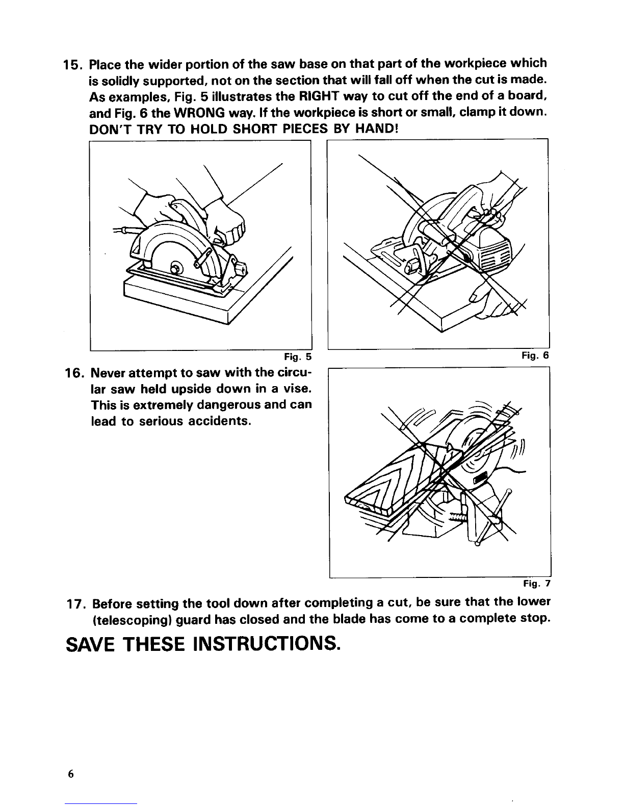
15.
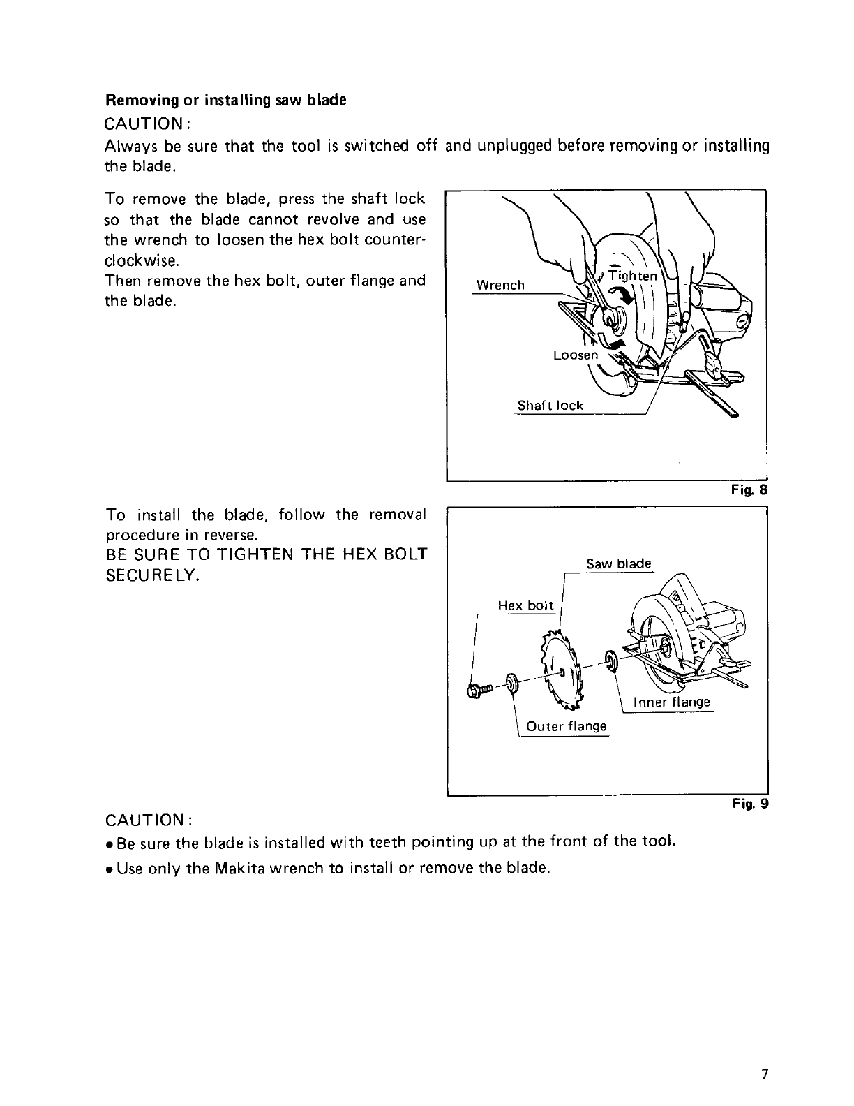
16.
17.
18.
19.
20.
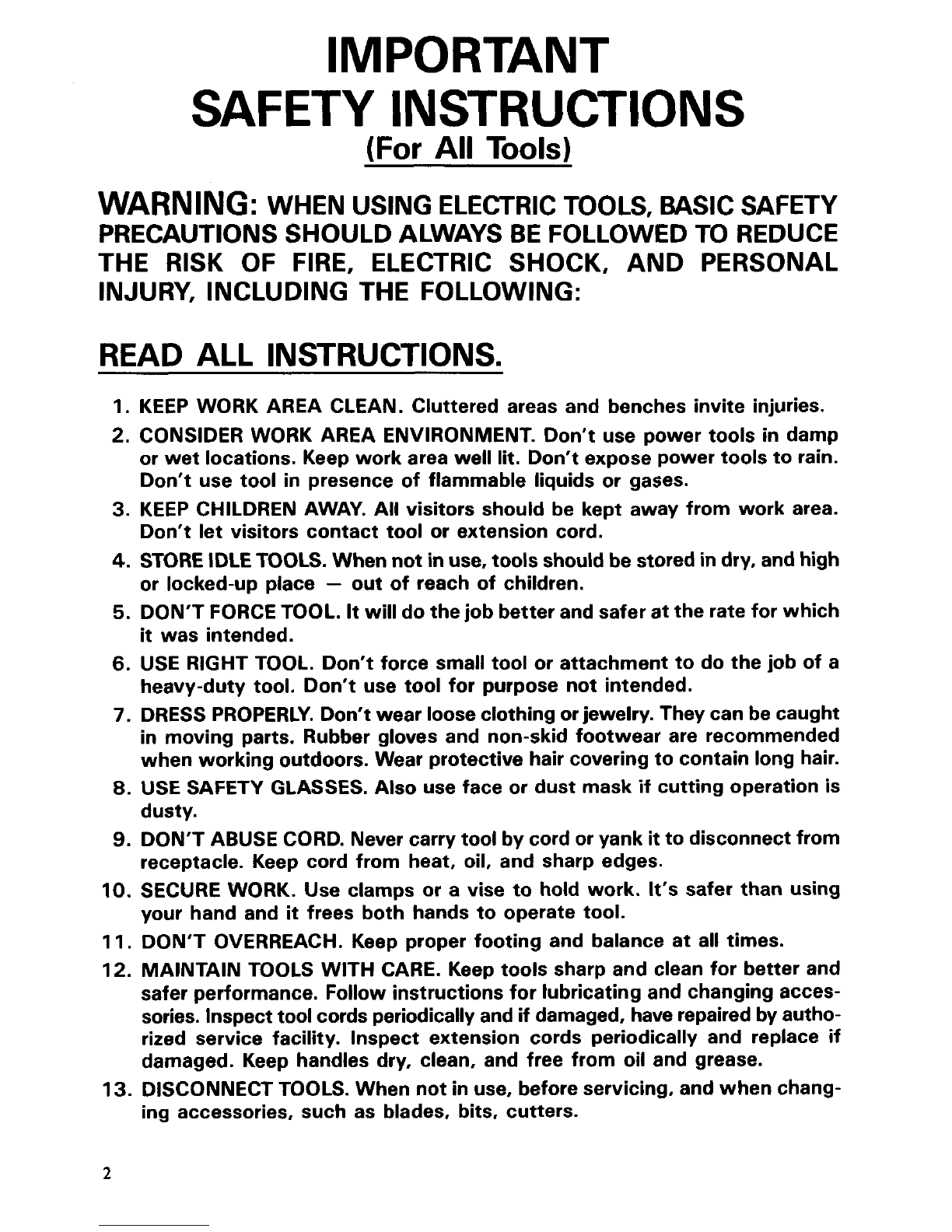
Ampere rating
(on nameplate)
Ext. Cable Length
25 Ft.
50 Ft.
75 Ft.
100Ft.
150Ft.
REMOVEADJUSTING KEYS AND WRENCHES. Form habit of checking to
seethat keysand adjusting wrenches are removed from tool beforeturning
it
on.
AVOID UNINTENTIONALSTARTING. Don’t carry plugged-in tool withfinger
on switch. Be sure switch is OFF when plugging in.
OUTDOOR USE EXTENSIONCORDS. Whentool is used outdoors, use only
extension cords intended for use outdoors and
so
marked.
STAY ALERT. Watch what youare doing, use commonsense. Don’t operate
tool when you are tired.
CHECK DAMAGED PARTS. Beforefurther use of the tool, a guard or other
part that is damaged should be carefully checked to determine that
it
will
operate properly and perform itsintended function. Check for alignment of
moving parts, binding of moving parts, breakage of parts, mounting, and
any other conditions that may affect its operation. A guard or other part
that is damaged should be properly repaired or replaced by an authorized
service center unless otherwise indicated elsewhere
in
this instruction
manual. Havedefective switchesreplacedbyauthorized service center. Don’t
use tool if switch does not turn
it
on and off.
GUARD AGAINST ELECTRIC SHOCK. Prevent body contact withgrounded
surfaces. For example; pipes, radiators, ranges, refrigerator enclosures.
REPLACEMENTPARTS. When servicing, useonly identicalreplacement parts.
0-
2.10
-
3.50
-
5.10
-
7.10
-
12.10
-
2.00 3.40 5.00
7.00
12.00 16.00
Wire
Size
(AmericanWire Gauge)
18 18 18 18 16 14
18 18 18 16 14 12
18 18 16 14 12 10
18 16 14 12 10
~
16 14 12 12
- -
VOLTAGE WARNING: Before connectingthe tooltoa power source (receptacle,
outlet, etc.) be sure the voltage supplied is the same as that specified on the
nameplateof the tool. A power source with voltage greater than that specified
for the tool can result
in
SERIOUS INJURY to the user
-
as well as damage to
the tool.
If
in doubt, DO NOT PLUG INTHE TOOL. Using a power source with
voltage less than the nameplate rating is harmful to the motor.
Use Of Extension Cord
If the extension cord isintended to be used outdoors, the cord shall be marked
withthe suffix W-A following the cord type designation, for example
-
SJTW-
A, to indicate
it
is acceptable for outdoor use. Use an extension cord heavy
enoughto carry the current the toolwill draw. Undersize cord will cause a drop
in
line voltage resulting
in
loss
of power and over-heating. Makesure the exten-
sion cord is in good condition before using. Use the table below to determine
the proper wire size required
in
the extension cord.