Makita 5477NB Manual

Continuous Rating (W)
Voltage (V) Cycle (Hz) Input Output Max. Output (W)
15120 50 - 60
4,500
185 (7-1/4)
15.88 (5/8)
60 (2-3/8)
44 (1-3/4)
40 (1-9/16)
Double insulation
6.3 (13.9)
3.0 (9.8)
1,000 2,300
Models No.
Description
PRODUCT
Current
T
ECHNICAL INFORMATION
CONCEPT AND MAIN APPLICATIONS
Specification
Standard equipment
Optional accessories
Note: The standard equipment for the tool shown above may differ by country.
P 1/ 8
5477NB
Hypoid Saw 185mm (7-1/4")
Model 5477NB has been developed as the cost-competitive successor
tool of the current 5277NB.
No load speed: rpm=min.-1
Saw blade: mm (")
Max. cutting
capacities: mm (")
Net weight: kg (lbs)
Cord length: m (ft)
Diameter
at 90 degrees
at 45 degrees
at 50 degrees
Protection from electric
Hole diameter
TCT saw blade .......................... 1
Hex wrench ................................ 1
Circular saw blades
Guide rule
Tool hook
Dimensions: mm (")
Width (W1)
Height (H1)
Length (L1) 442 (17-3/8)
183 (7-1/4)
254 (10)
Height (H2) 186 (7-3/8)
Base Size: mm (")
Width (W2)
Length (L2) 295 (11-5/8)
132 (5-3/16)
W1
H1
L1
H2
W2
L2

P 2/ 8
[2] LUBRICATION
[3] DISASSEMBLY/ ASSEMBLY OF BASE
When assembling Gear section;
1) Wash the inside of Gear housing complete clean with kerosene.
2) Put 30cc Lubricant oil VG220 (Makita part No. 041005-1A: 20 liters per tank) as illustrated in Fig. 1 to protect parts
and product from unusual abrasion.
Fig. 1
[1] NECESSARY REPAIRING TOOLS
CAUTION: Unplug the machine and remove the saw blade from the machine for safety before
repair/ maintenance !
Code No. Descriptions Use for
Gear housing complete
Repair
1R003
1R207
1R269
1R291
1R316
Retaining ring S pliers ST-2N
45 degrees set square
1R208 90 degrees set square
Bearing extractor
Retaining ring S and R pliers
Bearing retainer wrench
Removing Retaining ring S-42 to separate Safety cover from Gear housing complete
Adjusting Saw blade to be at right angle with Base
Removing Ball bearings
Disassembling / Assembling Retaining rings
Disassembling / Assembling Bearing retainers
Put Lubricant oil VG220 or the following API (American Petroleum Institute) GL-4
vehicle gear oil into Gear room from the Armature gear shaft installation side.
Twist the Bow stop ring E-12 using slotted screw-
driver to remove it from a groove of M8-13 Hex nut.
Remove Bow stop rings E-12 on Depth guide. (Fig. 2) Lever plate, M8-13 Hex nut, Flat washer 8 (small) and Flat washer 8
(large) can be removed as illustrated in Fig. 3.
Fig. 3Fig. 2
M8-13 Hex nut
M8-13 Hex nut
Flat washer 8 (small) Flat washer 8 (large)
Bow stop ring E-12
Bow stop ring E-12
Depth guide
Lever plate
Lever plate
Bow stop
ring E-12
Nippon Oil
Hypoid Gear
80, 90, 140
Idemitsu
Apollo Gear
HE-80W, 90
COSMO
Gear GL-4
80, 90, 140
Shell
Shell Spirax EP75W-
85, 80, 90, 140
Castrol
TAF-X 75W-90
MTF-S 75W-90
MTF 80W-90
BP
Gear Oil 80W-90
ELF TOTAL
Gearelf HTX 740
Retro G 80W
TOTAL EP
80W85, 80W90
TOTAL Transmission
X1 75W90, T1 75W80
DISASSEMBLING

P 3/ 8
2) Remove the other Bow stop ring E-12, Lever plate, M8-13 Hex nut, Flat washer 8 (small) and M8x24 Cap square neck
bolt on the angular guide of Base. (Fig. 4)
3) Remove M8 Flat head screw on the angular guide. (Fig. 5) Base can be removed.
Do the reverse of the disassembling steps.
Note: 1) Be sure to set Flat washer 8 (large) in place when assembling Depth guide and the relative parts.
2) Secure Lever plate with Bow stop ring E-12. Bow stop ring E-12 isn't reversible when assembled.
Be sure to face the curved shape toward outside. (Fig. 6)
Repair
Bow stop
ring E-12Lever plate
Flat washer 8 (small)
M8x28 Cap
square neck bolt
M8-13
Hex nut
Fig. 4
Fig. 6
Fig. 5
M8-13 Hex nut
Flat washer 8
Lever plate
Bow stop ring E-12
Wrong
(The curved shape
faces inside.)
Curved
Curved
Outside
Inside (to Motor section)
Correct
[3] DISASSEMBLY/ ASSEMBLY OF BASE (cont.)
DISASSEMBLING
ASSEMBLING
angular guide
of Base
M8 Flat head screw
Base
M8 Hex. nut
Stopper plateO ring 12Flat washer 8 (small)Spring washer 8
1) Remove Base from Motor section.
2) Safety cover and Spacer can be removed by extracting Retaining ring S-42 with 1R003. (Fig. 7) Spacer and Tension
spring 4 can also be removed. (Fig. 8)
3) Remove M5x18 Pan head screws (2pcs.) and M6x16 Pan head screw. (Fig. 8)
Grip, Hook assembly and Cover complete can be removed from Gear housing complete.
[4] DISASSEMBLY/ASSEMBLY OF GEAR SECTION
M6x16 Pan head screw
Grip
Hook assembly
(optional accessory)
M5x18 Pan head
screw
Cover complete
SpacerSafety cover
1R003
Safety cover
Retaining ring S-42
Retaining ring S-42
Tension spring 4
Fig. 7 Fig. 8
DISASSEMBLING

Lubricant oil
Gear part of
Armature
P 4/ 8
Repair
[4] DISASSEMBLY/ ASSEMBLY OF GEAR SECTION (Cont.)
M5x35 Pan head
screw M5x18 Pan
head screw Bearing box
(Ball bearing 6001ZZ comes with this bearing box.)
Hypoid gear 36
Hypoid gear 36
Spindle
Flat washer 12
Carbon brush
Brush holder cap
Spindle lock button
Fig. 9 Fig. 10
Fig. 11 Fig. 12
Fig. 13
M5x35 Pan head
screw
Gear housing complete
Armature
Fig. 14
4) Gear housing complete is secured with M5x35 Pan head screws (2pcs.) on Spindle lock button side and with the other
M5x35 Pan head screws (2pcs.) on Blade case side.
First, remove M5x35 Pan head screws (2pcs.) on Spindle lock button side. (Fig. 9)
5) Bearing box can be removed by removing M5x18 Pan head screws (3pcs.). (Fig. 10)
6) Put Gear housing complete onto the vessel for collecting lubricant oil with its Bearing assembly side down.
Hypoid gear 36, Flat washer 12 and Lubricant oil are fallen down from Gear housing complete. (Fig. 11)
Note: Pay attention not to lose Woodruff key in this step.
7) Remove Depth guide and remove Brush holder cap.
Carbon brush on Blade case side can be removed from Motor housing complete. (Fig. 12)
8) Remove M5x35 Pan head screws (2pcs.) on Blade case side. (Fig. 12)
9) Temporarily fix Gear housing complete to Motor housing complete with M5x35 Pan head screws (2pcs.) screwed
halfway in the screw holes as illustrated in Fig.13. Strike the screws head gently with plastic hammer.
Gear housing complete is removed from Motor housing complete as illustrated in Fig.14.
Vessel for collecting
Lubricant oil
Motor housing complete
Spindle
Woodruff key
DISASSEMBLING

P 5/ 8
Repair
[5] DISASSEMBLY/ASSEMBLY OF GEAR SECTION (cont.)
DISASSEMBLING
ASSEMBLING
1R316
Ball bearing
6003LLB
Bearing
retainer 23-36
Gear housing
complete
Gear housing
complete
Bearing retainer
M5x18 Pan head screw
Armature
Spindle
Fan 45
Fig. 15 Fig. 16 Fig. 17
10) Remove M5x18 Pan head screws (2pcs.).
Remove Armature with Bearing retainer not to cause damage to Fan 45 in Gear housing complete. (Fig. 15)
11) Disassemble Spindle with Fan 45 by striking the Spindle end from Blade installation-side with plastic hammer.
(Fig. 16)
12) Remove Bearing retainer 23-36 from Gear housing complete by turning it counterclockwise with 1R316. (Fig. 17)
1) Clean the Gear room thoroughly before assembling the Gear section.
2) Press-fit Ball bearing 6003LLB into Gear housing complete and tighten Bearing retainer 23-36 with 1R316 by turning
it clockwise.
3) Press-fit Spindle into Fan 45 from Shaft lock button side.
4) While holding Woodruff key in the groove of Spindle by hand, assemble Hypoid gear 36 and Flat washer 12 to Spindle
with Woodruff key. (Fig. 18)
5) Mount O ring 53 to Bearing box and then assemble Bearing box with Ball bearing 6001ZZ to Gear housing complete.
(Fig. 18)
6) Apply the Lubricant oil as illustrated in Fig. 19. (Refer to Fig. 1 for the details.)
7) Assemble Armature section to Gear housing complete.
Woodruff key
Hypoid gear 36
Bearing box
M5x18 Pan head screw
Fig. 18 Fig. 19
Flat washer 12
O ring 53
Ball bearing 6001LLB comes with
this Bearing box.
Lubricant
oil

P 6/ 8
[6] DISASSEMBLY/ ASSEMBLY OF ARMATURE SECTION
Repair
Fig. 21Fig. 20L Fig. 20R
Wrong
Correct
Fig. 22 Fig. 23
Ball bearing 6003LLB
O ring 16
Ring 17
Water pump pliers with which
the legs of 1R269 are clamped.
Note: O ring 16 has to be replaced with new one
whenever Ball bearing 6003LLB is removed.
Note: Be careful not to scratch
its surface where Oil seal 22
contacts.
Note: It is not necessary to remove Bearing box from Gear housing complete when replacing Armature.
1) Separate Base from Motor section. (Figs 2 to 5)
2) After Removing Depth guide from Motor housing complete, remove Carbon brush.
3) Separate Gear housing complete from Motor housing complete after removing M5x35 Pan head screws (4pcs.).
(Figs. 9, 12, 14 and 15)
4) Remove Armature section upward from Gear housing complete while holding Gear housing complete with Armature
section positioned in Fig. 20L.
Note: Do not remove Armature section downward and horizontally from Gear housing complete (Fig. 20R).
Because Gear oil remaining inside is drained out from Gear housing complete.
5) Remove Retaining ring S-17 using 1R291. (Fig. 21)
6) Remove Ball bearing 6003LLB, O ring 16 and Ring 17 using 1R269 and water pump pliers. (Fig. 22)
7) Bearing retainer can be removed from Armature. (Fig. 23)
Gear oil
M5x18 Pan head screw
Retaining ring S-17
1R291
1R269
Bearing retainer
DISASSEMBLING

P 7/ 8
[6] DISASSEMBLY/ASSEMBLY OF ARMATURE SECTION (Cont.)
Repair
ASSEMBLING
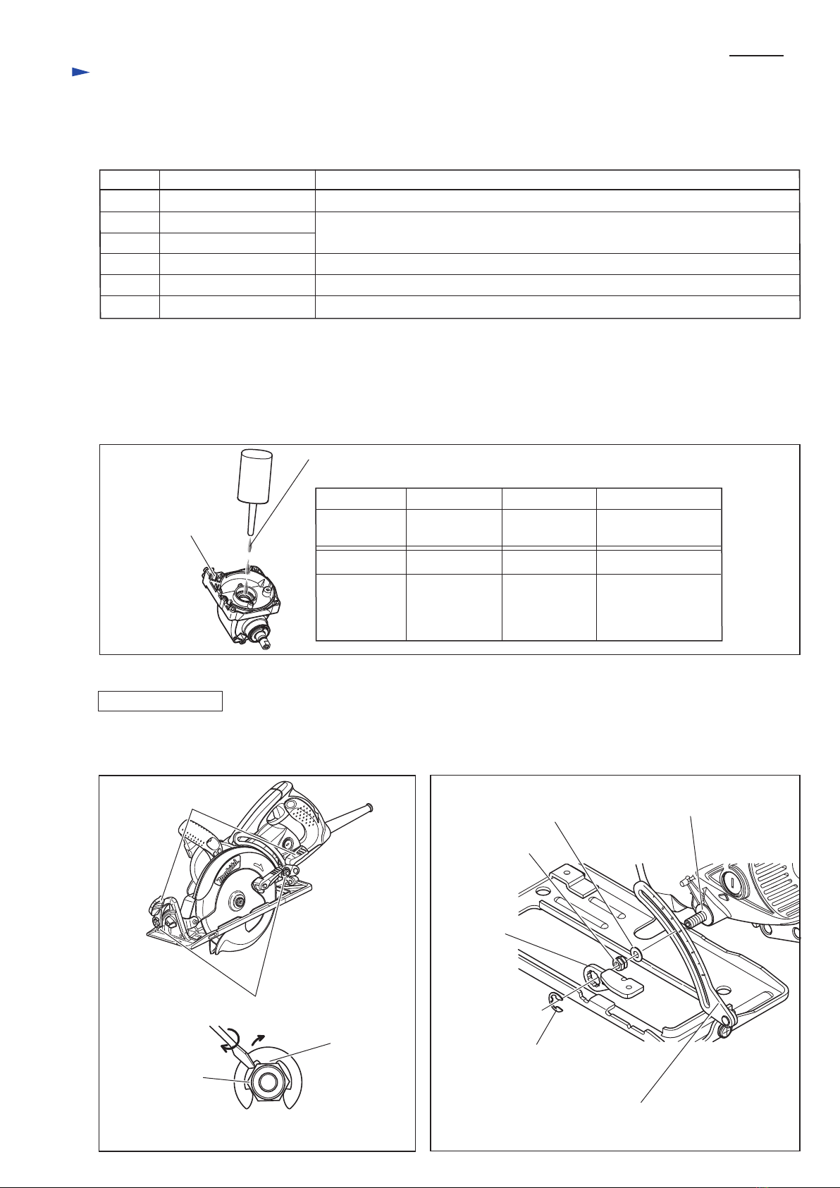
1) Mount Bearing retainer to Armature. Press-fit Ball bearing 6003LLB into Armature shaft.
2) Push new O ring 16 by hand until it contacts to the inner ring of Ball bearing 6003LLB as illustrated in Fig. 24.
3) Press-fit Ring 17 as illustrated in Fig.25. Pay attention to the direction of Ring 17.
4) Secure the their assembled parts by installing Retaining ring S-17 into the groove of Armature shaft.
5) Assemble the armature section while holding gear housing complete as illustrated in Fig. 20L.
Ball bearing 6003LLB
Bearing retainer
Inner ring of Ball bearing 6003LLB
O ring 16
Armature shaft Armature shaft
Ring 17
Groove for O ring 16
Groove for Retaining ring S-17
O ring 16
Fig. 24 Fig. 25
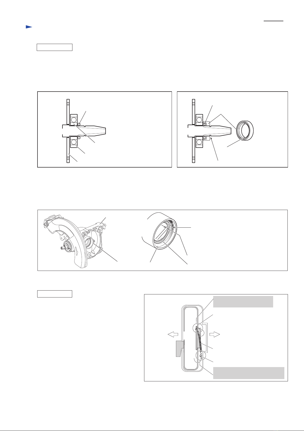
[7] ASSEMBLY OF OIL SEAL 22 IN GEAR HOUSING COMPLETE
0.5mm deeper than the rim
Rim
( Armature's Ball bearing 6003LLB
is accepted by this rim.)
Gear housing complete
When assembling Oil seal 22 to Gear housing complete, press-fit it for 0.5mm deeper than the rim for accepting Ball
bearing 6003LLB using 0.5mm thickness flat washer. Be sure to remove the 0.5mm thickness flat washer from Bearing
box after setting Oil seal 22 in place. (Fig. 26)
Oil seal 22
Bearing box part
Fig. 26
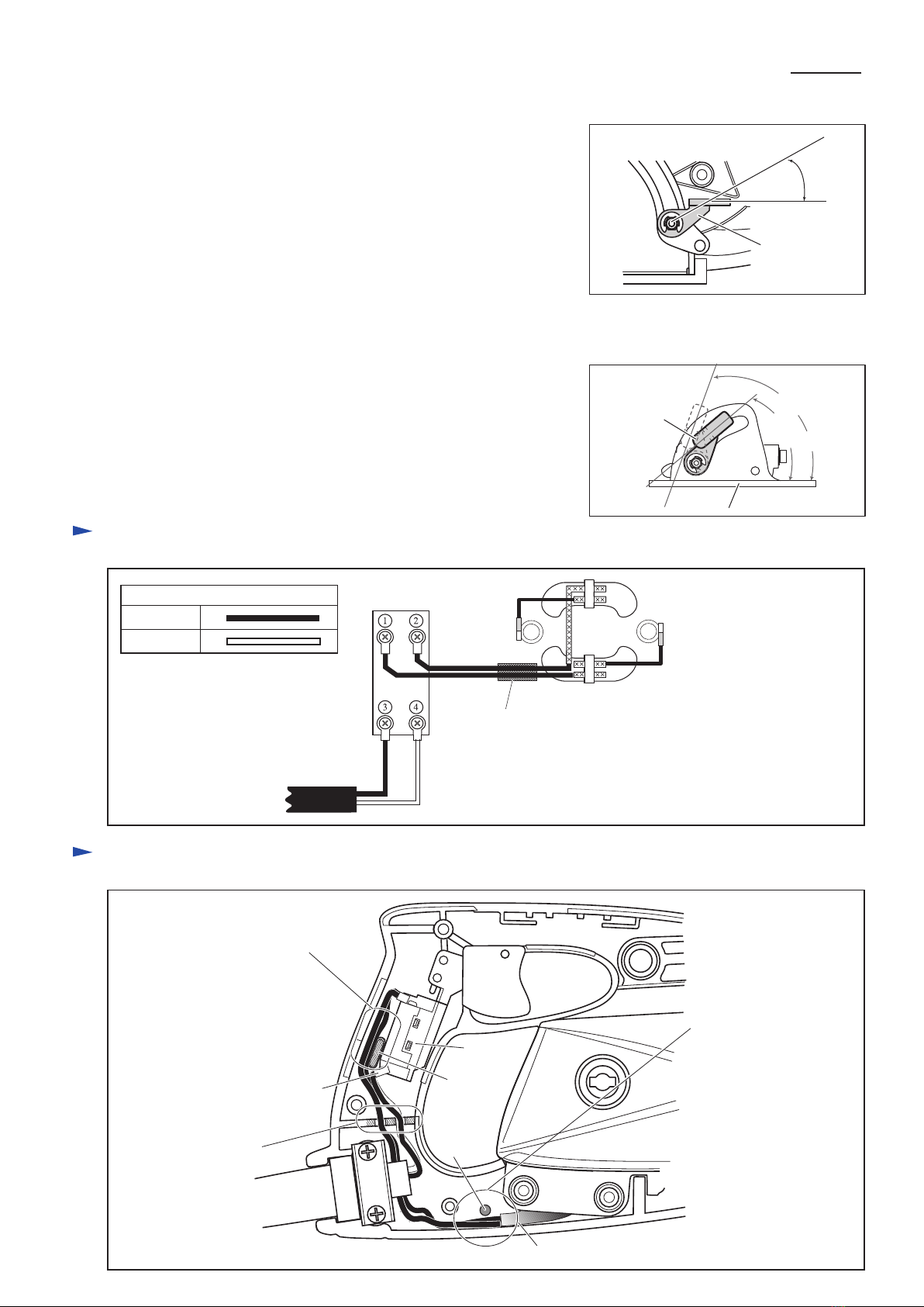
[8] ASSEMBLY OF TENSION SPRING 4 FOR SAFETY COVER
[9] FINE ADJUSTMENT OF BASE TO SAW BLADE AT 90 DEGREES
ASSEMBLING
When connecting Safety cover to Blade case with
Tension spring 4, hook the end of Tension spring 4
as illustrated in Fig. 27.
Adjust the angular deviation by loosening/tightening M5x8 Hex. socket set screw for adjusting bevel angle and by using
1R208. See the instruction manual for the details.
Blade side
Safety cover
Tension spring 4
Blade case
Gear housing Side
Pass the hook from Gear
housing side to Blade side.
Pass the hook from blade side to
Gear housing side.
Fig. 27

Circuit diagram
Wiring diagram
P 8/ 8
Switch
Polyethylene tube
Field
Fig. D-1
Fig. D-2
Fig. 29
Power supply cord
Color index of lead wires' sheath
Black
White
The assembled angle of Lever plate and Base has to be adjusted in the zone
from 40 degrees to 70 degrees as illustrated in Fig. 29 when blade angle to
Base is set at 90 degrees.
The assembled angle of Lever plate and Depth guide has to be adjusted in
the zone from 0 degree to 30 degrees as illustrated in Fig. 28.
Fig. 28
70 degrees
40
degrees
30
degrees
Lever plate
Base
Lever plate
[11] ADJUSTMENT IN POSITION OF LEVER PLATE FOR ANGULAR GUIDE
[10] ADJUSTMENT IN POSITION OF LEVER PLATE FOR DEPTH GUIDE
Rib
Pin
Polyethylene Tube for bundling field lead wires
Fix the lead wires into
the lead wire holders.
Inflect the connecting terminal
so that it does not interfere with
the wiring of lead wires.
Route the field lead wires between
rib and the wall of Handle set.
Route the field lead wires
between pin and the wall
of handle set to keep the
polyethylene tube in the
illustrated position.
Power Supply Cord
Switch
Other manuals for 5477NB
2
Table of contents
Other Makita Saw manuals

Makita
Makita HS6100 User manual

Makita
Makita 5703R User manual

Makita
Makita DLW140 User manual

Makita
Makita LS1030N User manual

Makita
Makita JR002G User manual

Makita
Makita JR100D User manual

Makita
Makita LS1013L Quick start guide

Makita
Makita DPB183 User manual

Makita
Makita LS1019 User manual

Makita
Makita JR3060T User manual

Makita
Makita HS6100 User manual

Makita
Makita GSL04 User manual

Makita
Makita BSS501 Quick start guide

Makita
Makita 5057KB User manual

Makita
Makita LS1221 User manual

Makita
Makita M2400 User manual

Makita
Makita LC1230 User manual

Makita
Makita EA3200S User manual

Makita
Makita 2704 User manual

Makita
Makita LS0815F User manual