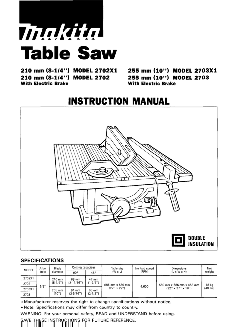
Makita 2704N User manual

2704N
EN Table Saw INSTRUCTION MANUAL 9
SV Bordssåg BRUKSANVISNING 18
NO Bordsag BRUKSANVISNING 27
FI Pöytäpyörösaha KÄYTTÖOHJE 36
LV Galda zāģis LIETOŠANAS INSTRUKCIJA 45
LT Medžio pjovimo staklės NAUDOJIMO INSTRUKCIJA 54
ET Töölauale paigaldatav saag KASUTUSJUHEND 63
RU Настольный
Распиловочный Станок
РУКОВОДСТВО ПО
ЭКСПЛУАТАЦИИ 72

620 mm
1
525 mm
Fig.1
1
25 mm
2
Fig.2
12
Fig.3
1
Fig.4
1
2
3
Fig.5
12
Fig.6
1
Fig.7
12
3
Fig.8
2

12
Fig.9
(A)
(B)
90
90 45
45
Fig.10
1
Fig.11
1
Fig.12
12
3
4
Fig.13
3
4
2
12
1
2
Fig.14
1
Fig.15
3

1
Fig.16
1
2
Fig.17
2
1
2
Fig.18
1
1
2
Fig.19
21
Fig.20
1
32
Fig.21
12
3
45
Fig.22
1
2
Fig.23
4

12
3
Fig.24
1
2
3
4
5
Fig.25
1
2
3
Fig.26
12
3
3
Fig.27
1
A
B
Fig.28
1
Fig.29
Fig.30
1
2
3
4
Fig.31
5

12
3
4
Fig.32
1
2
Fig.33
Fig.34
120mm
300mm
130mm
50mm
6mm
300mm
130mm
100mm
50mm
9.5mm
50mm
8mm
1
2
3
4
Fig.35
9.5mm
19mm 120mm
40mm
140mm
460mm
1
Fig.36
Fig.37
6

Fig.38
1
Fig.39
Fig.40
1
2
Fig.41
12
34
Fig.42
2
3
1
Fig.43
1
3
2
Fig.44
1
Fig.45
7

Fig.46
1
Fig.47
1
2
3
Fig.48
Fig.49
1
23
Fig.50
8

9ENGLISH
ENGLISH (Original instructions)
SPECIFICATIONS
Model: 2704N
Arbor hole
(Country specic)
30 mm / 25.4 mm
Blade diameter 260 mm
Max. cutting capacities bevel 0° 93 mm
bevel 45° 64 mm
No load speed 5,200 min-1
Table size (L x W) with sub tables (R) and (back) 1,045 mm x 1,066 mm (tables extended)
665 mm x 753 mm (tables stored)
with sub table (R)
without sub table (back)
567 mm x 1,066 mm (table extended)
567 mm x 753 mm (table stored)
Dimensions (L x W x H) with
table(s) not extended
with sub tables (R) and (back) 715 mm x 753 mm x 483mm
with sub table (R)
without sub table (back)
665 mm x 753 mm x 483 mm
Net weight 35.2 kg - 37.0 kg
Safety class /II
• Due to our continuing program of research and development, the specications herein are subject to change
without notice.
• Specications may differ from country to country.
• The weight may differ depending on the attachment(s). The lightest and heaviest combination, according to
EPTA-Procedure 01/2014, are shown in the table.
Symbols
The following show the symbols used for the equip-
ment. Be sure that you understand their meaning before
use.
Read instruction manual.
DOUBLE INSULATION
Wear safety glasses.
Do not place hand or ngers close to the
blade.
Only for EU countries
Do not dispose of electric equipment
together with household waste material! In
observance of the European Directive, on
Waste Electric and Electronic Equipment
and its implementation in accordance with
national law, electric equipment that have
reached the end of their life must be col-
lected separately and returned to an envi-
ronmentally compatible recycling facility.
Intended use
The tool is intended for cutting in wood.
Straight cutting, bevel cutting, and miter cutting are
available with this tool. This tool is not designed for non-
through cutting.
Power supply
The tool should be connected only to a power supply of
the same voltage as indicated on the nameplate, and
can only be operated on single-phase AC supply. They
are double-insulated and can, therefore, also be used
from sockets without earth wire.
Noise
The typical A-weighted noise level determined accord-
ing to EN62841:
Sound pressure level (LpA) : 94 dB(A)
Sound power level (LWA) : 107 dB (A)
Uncertainty (K) : 3 dB(A)
WARNING: Wear ear protection.
EC Declaration of Conformity
For European countries only
The EC declaration of conformity is included as Annex A
to this instruction manual.

10 ENGLISH
SAFETY WARNINGS
General power tool safety warnings
WARNING: Read all safety warnings, instruc-
tions, illustrations and specications provided
with this power tool. Failure to follow all instructions
listed below may result in electric shock, re and/or
serious injury.
Save all warnings and instruc-
tions for future reference.
The term "power tool" in the warnings refers to your
mains-operated (corded) power tool or battery-operated
(cordless) power tool.
Safety instructions for table saws
Guarding related warnings
1. Keep guards in place. Guards must be in work-
ing order and be properly mounted. A guard
that is loose, damaged, or is not functioning cor-
rectly must be repaired or replaced.
2.
Make sure the saw blade is not contacting the
guard, riving knife or the workpiece before the
switch is turned on. Inadvertent contact of these items
with the saw blade could cause a hazardous condition.
3. Adjust the riving knife as described in this
instruction manual. Incorrect spacing, position-
ing and alignment can make the riving knife inef-
fective in reducing the likelihood of kickback.
4.
For the riving knife and anti-kickback pawls to
work, they must be engaged in the workpiece.
The riving knife and anti-kickback pawls are ineffec-
tive when cutting workpieces that are too short to
be engaged with the riving knife and anti-kickback
pawls. Under these conditions a kickback cannot be
prevented by the riving knife and antikickback pawls.
5. Use the appropriate saw blade for the riving
knife. For the riving knife to function properly, the
saw blade diameter must match the appropriate
riving knife and the body of the saw blade must be
thinner than the thickness of the riving knife and
the cutting width of the saw blade must be wider
than the thickness of the riving knife.
Cutting procedures warnings
1. DANGER: Never place your ngers or
hands in the vicinity or in line with the saw
blade. A moment of inattention or a slip could
direct your hand towards the saw blade and result
in serious personal injury.
2.
Feed the workpiece into the saw blade only
against the direction of rotation. Feeding the
workpiece in the same direction that the saw blade is
rotating above the table may result in the workpiece,
and your hand, being pulled into the saw blade.
3.
Never use the mitre gauge to feed the workpiece
when ripping and do not use the rip fence as a
length stop when cross cutting with the mitre
gauge. Guiding the workpiece with the rip fence
and the mitre gauge at the same time increases the
likelihood of saw blade binding and kickback.
4.
When ripping, always apply the workpiece feed-
ing force between the fence and the saw blade.
Use a push stick when the distance between the
fence and the saw blade is less than 150 mm,
and use a push block when this distance is less
than 50 mm. “Work helping” devices will keep your
hand at a safe distance from the saw blade.
5. Use only the push stick provided by the manu-
facturer or constructed in accordance with the
instructions. This push stick provides sufcient
distance of the hand from the saw blade.
6. Never use a damaged or cut push stick. A
damaged push stick may break causing your hand
to slip into the saw blade.
7.
Do not perform any operation “freehand”. Always
use either the rip fence or the mitre gauge to posi-
tion and guide the workpiece. “Freehand” means
using your hands to support or guide the workpiece,
in lieu of a rip fence or mitre gauge. Freehand sawing
leads to misalignment, binding and kickback.
8. Never reach around or over a rotating saw
blade. Reaching for a workpiece may lead to
accidental contact with the moving saw blade.
9. Provide auxiliary workpiece support to the rear
and/or sides of the saw table for long and/or
wide workpieces to keep them level. A long and/
or wide workpiece has a tendency to pivot on the
table’s edge, causing loss of control, saw blade
binding and kickback.
10. Feed workpiece at an even pace. Do not bend
or twist the workpiece. If jamming occurs, turn
the tool off immediately, unplug the tool then
clear the jam. Jamming the saw blade by the
workpiece can cause kickback or stall the motor.
11. Do not remove pieces of cut-off material while
the saw is running. The material may become
trapped between the fence or inside the saw blade
guard and the saw blade pulling your ngers into
the saw blade. Turn the saw off and wait until the
saw blade stops before removing material.
12. Use an auxiliary fence in contact with the table
top when ripping workpieces less than 2 mm
thick. A thin workpiece may wedge under the rip
fence and create a kickback.
Kickback causes and related warnings
Kickback is a sudden reaction of the workpiece due to a
pinched, jammed saw blade or misaligned line of cut in
the workpiece with respect to the saw blade or when a
part of the workpiece binds between the saw blade and
the rip fence or other xed object.
Most frequently during kickback, the workpiece is lifted
from the table by the rear portion of the saw blade and
is propelled towards the operator.
Kickback is the result of saw misuse and/or incorrect
operating procedures or conditions and can be avoided
by taking proper precautions as given below.
1. Never stand directly in line with the saw blade.
Always position your body on the same side of
the saw blade as the fence. Kickback may propel
the workpiece at high velocity towards anyone
standing in front and in line with the saw blade.
2. Never reach over or in back of the saw blade
to pull or to support the workpiece. Accidental
contact with the saw blade may occur or kickback
may drag your ngers into the saw blade.
11 ENGLISH
3. Never hold and press the workpiece that is
being cut off against the rotating saw blade.
Pressing the workpiece being cut off against the
saw blade will create a binding condition and
kickback.
4. Align the fence to be parallel with the saw
blade. A misaligned fence will pinch the workpiece
against the saw blade and create kickback.
5. Use extra caution when making a cut into blind
areas of assembled workpieces. The protrud-
ing saw blade may cut objects that can cause
kickback.
6. Support large panels to minimise the risk of
saw blade pinching and kickback. Large panels
tend to sag under their own weight. Support(s)
must be placed under all portions of the panel
overhanging the table top.
7. Use extra caution when cutting a workpiece
that is twisted, knotted, warped or does not
have a straight edge to guide it with a mitre
gauge or along the fence. A warped, knotted,
or twisted workpiece is unstable and causes mis-
alignment of the kerf with the saw blade, binding
and kickback.
8. Never cut more than one workpiece, stacked
vertically or horizontally. The saw blade could
pick up one or more pieces and cause kickback.
9. When restarting the saw with the saw blade in
the workpiece, centre the saw blade in the kerf
so that the saw teeth are not engaged in the
material. If the saw blade binds, it may lift up the
workpiece and cause kickback when the saw is
restarted.
10. Keep saw blades clean, sharp, and with suf-
cient set. Never use warped saw blades or saw
blades with cracked or broken teeth. Sharp and
properly set saw blades minimise binding, stalling
and kickback.
Table saw operating procedure warnings
1. Turn off the table saw and disconnect the
power cord when removing the table insert,
changing the saw blade or making adjust-
ments to the riving knife, anti-kickback pawls
or saw blade guard, and when the machine
is left unattended. Precautionary measures will
avoid accidents.
2. Never leave the table saw running unattended.
Turn it off and don’t leave the tool until it
comes to a complete stop. An unattended run-
ning saw is an uncontrolled hazard.
3. Locate the table saw in a well-lit and level area
where you can maintain good footing and
balance. It should be installed in an area that
provides enough room to easily handle the
size of your workpiece. Cramped, dark areas,
and uneven slippery oors invite accidents.
4. Frequently clean and remove sawdust from
under the saw table and/or the dust collection
device. Accumulated sawdust is combustible and
may self-ignite.
5. The table saw must be secured. A table saw that
is not properly secured may move or tip over.
6. Remove tools, wood scraps, etc. from the table
before the table saw is turned on. Distraction or
a potential jam can be dangerous.
7. Always use saw blades with correct size and
shape (diamond versus round) of arbour
holes. Saw blades that do not match the mounting
hardware of the saw will run off-centre, causing
loss of control.
8. Never use damaged or incorrect saw blade
mounting means such as anges, saw blade
washers, bolts or nuts. These mounting means
were specially designed for your saw, for safe
operation and optimum performance.
9. Never stand on the table saw, do not use it as
a stepping stool. Serious injury could occur if the
tool is tipped or if the cutting tool is accidentally
contacted.
10. Make sure that the saw blade is installed to
rotate in the proper direction. Do not use
grinding wheels, wire brushes, or abrasive
wheels on a table saw. Improper saw blade
installation or use of accessories not recom-
mended may cause serious injury.
Additional instructions
1. Only use the saw blades that are marked with
a speed equal or higher than the speed marked
on the tool.
2. Select the correct saw blade for the material to
be cut.
3. Wear gloves when handling saw blades.
4. Clean the spindle, anges (especially the
installing surface) and hex nut before install-
ing the blade. Poor installation may cause vibra-
tion/wobbling or slippage of the blade.
5. Do not cut metal objects such as nails and
screws. Inspect for and remove all nails,
screws and other foreign material from the
workpiece before operation.
6. NEVER permit anyone else to stand in line with
the path of the saw blade.
7. Before using the tool on an actual workpiece,
let it run for a while. Watch for vibration or
wobbling that could indicate poor installation
or a poorly balanced blade.
8. The tool should not be used for slotting, rab-
betting or grooving.
9. Replace the table insert when worn.
10. Always store the push-stick when it is not in
use.
11. Knock out any loose knots from workpiece
BEFORE beginning to cut.
12. Some dust created from operation contains
chemicals known to cause cancer, birth
defects or other reproductive harm Some
examples of these chemicals are:
— lead from lead-based-painted material
and,
— arsenic and chromium from chemical-
ly-treated lumber.
Your risk from these exposures varies,
depending on how often you do this type
of work. To reduce your exposure to these
chemicals: work in a well ventilated area and
work with approved safety equipment, such as
those dust masks that are specially designed
to lter out microscopic particles.

12 ENGLISH
13. Always make sure that sub guard is down and
at against saw-table before plugging in the
tool.
14. Inspect extension cords periodically and
replace if damaged.
15. (For European countries only)
Use only saw blades recommended by the
manufacturer and which conform to EN847-1.
INSTALLATION
Positioning table saw
► Fig.1: 1. Hole diameter 8 mm
► Fig.2: 1. 6 mm Std. washer 2. No.10 wood screw 40
mm min. length
► Fig.3: 1. 6 mm Std. washer 2. 6 mm Mounting bolt
& Nut tighten securely
Locate the table saw in a well lit and level area where
you can maintain good footing and balance. It should
be installed in an area that leaves enough room to
easily handle the size of your workpieces. The table
saw should be secured with four screws or bolts to the
work bench or table saw stand using the holes provided
in the bottom of the table saw. When securing the table
saw on the work bench, make sure that there is an
opening in the top of the work bench the same size as
the opening in the bottom of the table saw so the saw-
dust can drop through.
If during operation there is any tendency for the table
saw to tip over, slide or move, the work bench or table
saw stand should be secured to the oor.
Storing accessories
► Fig.4: 1. Miter gauge
► Fig.5: 1. Rip fence 2. Push stick 3. Anti-kickback
pawls
The miter gauge, saw blade and wrenches can be
stored on the left side of the base. Also the rip fence,
push stick, and anti-kickback pawls can be stored at the
right side of the base.
FUNCTIONAL
DESCRIPTION
CAUTION: Always be sure that the tool is
switched off and unplugged before adjusting or
checking function on the tool.
Blade guard
WARNING: Never defeat or remove the blade
guard. An exposed blade as a result of defeated
guarding may result in serious personal injury during
operation.
WARNING: Never use the tool if the blade
guard is damaged, faulty or removed. Operation of
the tool with a damaged, faulty or removed guard may
result in serious personal injury.
► Fig.6: 1. Blade guard 2. Sub guard
When cutting, push the workpiece toward the blade
with the lower edge of the sub guard contacting with the
main table. As the workpiece is fed, the blade guard and
the sub guard goes over the edge of the workpiece.
In the interest of your personal safety, always maintain
the blade guard and sub guard in good condition. Any
irregular operation of the blade guard and sub guard
should be corrected immediately. Check to assure that
the blade guard and the sub guard are down and the
lower edge of the sub guard contacts with the main
table when the workpiece is not fed.
If the see-through parts become dirty, or sawdust
adheres to them in such a way that the blade and/or
workpiece is no longer easily visible, unplug the tool
and clean the see-through parts carefully with a damp
cloth. Do not use solvents or any petroleum-based
cleaners because this may cause damage to the parts.
If see-through parts become discolored through age or
UV light exposure, contact a Makita service center for
a new parts. DO NOT DEFEAT OR REMOVE BLADE
GUARD AND SUB GUARD.
Adjusting the depth of cut
► Fig.7: 1. Handle
The depth of cut may be adjusted by turning the handle.
Turn the handle clockwise to raise the saw blade or
counterclockwise to lower it.
NOTE: Use a shallow depth setting when cutting thin
materials in order to obtain a cleaner cut.
Adjusting the bevel angle
► Fig.8: 1. Lock lever 2. Arrow pointer 3. Handwheel
Loosen the lock lever counterclockwise and turn the
handwheel until the desired angle (0° - 45°) is obtained.
The bevel angle is indicated by the arrow pointer.
After obtaining the desired angle, tighten the lock lever
clockwise to secure the adjustment.
CAUTION: After adjusting the bevel angle, be
sure to tighten the lock lever securely.

13 ENGLISH
Adjusting positive stops
► Fig.9: 1. 90°Adjusting screw 2. 45°Adjusting screw
► Fig.10
The tool is equipped with positive stops at 90° and 45°
to the table surface. To check and adjust the positive
stops, proceed as follows:
Move the handwheel as far as possible by turning it.
Place a triangular rule on the table and check to see
if the saw blade is at 90° or 45° to the table surface. If
the saw blade is at an angle shown in Fig. A, turn the
adjusting screws clockwise; if it is at an angle shown in
Fig. B, turn the adjusting screws counterclockwise to
adjust the positive stops.
After adjusting the positive stops, set the saw blade at
90° to the table surface. Then adjust the arrow pointer
so that its right edge is aligned to the 0° graduation.
► Fig.11: 1. Arrow pointer
Switch action
► Fig.12: 1. Switch
CAUTION: Before operation, make sure that
the tool is turned on and off.
To start the tool, press the ON ( I ) button.
To stop it, press the OFF ( O ) button.
Sub fence (rip fence)
► Fig.13: 1. Clamping screw 2. Rip fence 3. Sub
fence 4. Rail
If the rip fence comes close to the saw blade, use the
sub fence to support the workpiece. Loosen the clamp-
ing screw and slide the sub fence out of the rail. Attach
the sub fence as illustrated and tighten the clamping
screws.
When the rip fence is attached to the left side of the
saw blade, switch the sub fence position. Remove the
clamping screws, sub fence, and rail from the rip fence.
Loosely attach the rail on the right side of the rip fence
using the removed clamping screws. After that, attach
the sub fence and tighten the clamping screws.
► Fig.14: 1. Rip fence 2. Sub fence 3. Clamping
screw 4. Rail
Sub table (R)
► Fig.15: 1. Lever
► Fig.16: 1. Sub table (R)
This tool is provided with the sub table (R) on the right
side of the main table. To use the sub table (R), raise
both levers on the front right side, pull out the table (R)
fully and then lower the levers to secure it.
When using the sub table (R ), locate the scale plate
on the sub table after loosening the screw on it with
a screwdriver so that it becomes successive with the
scale plate on the main table.
► Fig.17: 1. Scale plate 2. Screw
Sub table (back)
Optional accessory
► Fig.18: 1. Sub table (back) 2. Screw
To use the sub table (back), loosen the screws on the
left and right hand sides under the table and pull it out
backwards to the desired length. At the desired length,
tighten the screws securely.
NOTE:
When using the sub table (back) during use of the
rip fence, pull out the sub table (back) more than 50 mm
so that it does not hit against the top end of the rip fence.
Sub table (L)
Optional accessory
► Fig.19: 1. Screw 2. Sub table (L)
Sub table (L) (optional accessory) can be installed on
the left side of the table to obtain wider space.
Anti-kickback pawls
WARNING: Use the Antikickback pawls when-
ever possible during the through cutting opera-
tions. This will help prevent the material from being
pushed forward into the operator during a kickback
situation which may result in serious personal injury.
► Fig.20: 1. Antikickback pawl 2. Clamp
To remove the anti-kickback pawls from the tool, loosen the
clamp on the root of the antikickback pawls and then pull them
out. To install, perform the removal procedure in reverse.
ASSEMBLY
CAUTION: Always be sure that the tool is
switched off and unplugged before carrying out
any work on the tool.
Installing or removing saw blade
CAUTION: Always be sure that the tool is
switched off and unplugged before installing or
removing the saw blade.
CAUTION: Use only the Makita wrench pro-
vided to install or remove the saw blade. Failure
to do so may result in overtightening or insufcient
tightening of the hex bolt. This could cause an injury.
CAUTION: Use the following saw blade. Do
not use saw blades which do not comply with the
characteristics specied in these instructions.
Diameter Blade thickness Kerf
260 mm Less than 1.9 mm More than 2.1 mm
1.
Loosen the screw on the table insert and remove it.
2. Hold the outer ange with the offset wrench and
loosen the hex nut counterclockwise with the wrench.
Then remove the outer ange.
► Fig.21: 1. Offset wrench 2. Hex nut 3. Wrench

14 ENGLISH
3. Assemble the inner ange, ring, saw blade, outer
ange and hex nut onto the arbor, making sure that the
teeth of the blade are pointing down at the front of the
table. Always install the hex nut with its recessed side
facing the outer ange.
► Fig.22: 1. Inner ange 2. Ring 3. Saw blade
4. Outer ange 5. Hex nut
CAUTION: Be sure that the saw blade is
installed so that the teeth are aligned in the cut-
ting (turning) direction.
CAUTION: Check the arbor hole diameter of
the saw blade before installing the saw blade.
Always use the correct ring for the arbor hole of
the saw blade you intend to use. The size of the
supplied ring(s) varies depending on the country.
• For tool for a 30 mm hole-diameter saw blade,
the ring 30 mm in outer diameter is provided.
•
For tool for a 25.4 mm and 25 mm hole-diameter saw
blade, the silver and black rings are provided. Use the
silver ring for 25.4 mm hole-diameter saw blade and
the black ring for 25 mm hole-diameter saw blade.
4. To secure the saw blade in place, hold the outer
ange with the offset wrench, then tighten the hex nut
clockwise with the wrench. BE SURE TO TIGHTEN
THE HEX NUT SECURELY.
► Fig.23: 1. Offset wrench 2. Wrench
CAUTION:
Keep the ange surface clean of dirt or
other adhering matter; it could cause blade slippage.
CAUTION: Be sure to hold the hex nut care-
fully with the wrench. If your grip should slip, the
wrench may come off the hex nut, and your hand
could strike the sharp blade edges.
5. Attach the table insert in place with the screw.
Adjusting the riving knife
CAUTION:
If the saw blade and riving knife are
not aligned properly, a dangerous pinching condition
may result during operation. Make sure they are prop-
erly aligned. You could suffer serious personal injury
while using the tool without a properly aligned riving knife.
CAUTION: NEVER make any adjustments
while tool is running. Disconnect the tool before
making any adjustments.
CAUTION: Don't remove the riving knife.
► Fig.24: 1. Blade guard 2. Riving knife 3. Screw
The riving knife position is factory-adjusted so that
the saw blade and riving knife will be in a straight line.
However, you need to adjust it if the saw blade and
riving knife are not in a straight line.
Loosen the screw on the table insert and remove it from
the main table. Loosen the hex bolts (B) and adjust the
blade guard mounting portion (stay) so that the riving
knife is aligned directly behind the saw blade. Then
tighten the hex bolts (B) to secure the stay and put the
table insert in place.
► Fig.25: 1. Blade 2. These two clearances should be
equal. 3. Riving knife 4. Hex bolts (B) 5. Hex
bolts (A)
There must be a clearance of about 4 - 5 mm between
the riving knife and the blade teeth. Loosen the hex
bolts (A), adjust the riving knife accordingly and tighten
the hex bolts (A) securely. Attach the table insert on the
table with the screw, then check to see that the blade
guard works smoothly before cutting.
► Fig.26: 1. Riving knife 2. Blade guard 3. 4 mm -
5mm clearance
Installing and adjusting rip fence
► Fig.27: 1. Hook 2. Knob 3. Guide rail
1. Fit the hook on the tip of the rip fence into the far
guide rail on the table or sub table (R) and install and
push the rip fence forward so that the fence holder
engages with the nearmost guide rail.
2. To slide the rip fence on the guide rail sideways,
return the knob on the fence holder fully without pulling
the lever on the knob.
To secure the rip fence, pivot fully the knob on the fence
holder.
3. To remove the rip fence, pull the lever on the knob
and pivot the knob fully forward while pulling the lever.
To check if the rip fence is parallel with the saw blade,
secure the rip fence 2 - 3 mm from the saw blade. Raise
the blade up to maximum elevation. Mark one of the
blade teeth with a crayon. Measure the distance (A) and
(B) between the rip fence and saw blade. Take both mea-
surements using the tooth marked with the crayon. These
two measurements should be identical. If the rip fence is
not parallel with the saw blade, proceed as follows:
► Fig.28: 1. Scale
1. Position the rip fence in the sliding position.
2. Loosen the two hex bolts on the rip fence with the
hex wrench provided.
► Fig.29: 1. Hex bolts
3. Adjust the rip fence until it becomes parallel with
the saw blade.
4. Pivot down the knob on the rip fence toward the
operator.
5. Tighten the two hex bolts on the rip fence.
► Fig.30
CAUTION: Be sure to adjust the rip fence so
that it is parallel with the saw blade, or a danger-
ous kickback condition may occur.
When the rip fence cannot be secured solidly, adjust it
according to the following procedure.
1. Set the rip fence on the table and then pivot the
knob on the half way of its travel (moving position).
Tighten the screw (A) until the rip fence is immobilized.
Then loosen a 1/4 to 1/2 turn.
► Fig.31: 1. Rip fence 2. Released position 3. Moving
position 4. Lock position
► Fig.32: 1. Rip fence 2. Moving position 3. Screw (B)
4. Screw (A)
2. Tighten the screw (B) fully and then loosen about
2 full revolutions.
3. Lock the rip fence by fully pivoting the knob on the
fence holder (lock position).

15 ENGLISH
4. Make sure that the rip fence can be installed and
removed in the original position (released position).
5. Make sure that the rip fence can be slid smoothly
with no wobble when the knob is on half way of its
travel.
NOTICE: Be careful not to tighten screws with
more than tightening amount specied in the
above instructions. Failure to do so may damage
the fastened parts.
Bring the rip fence up ush against the side of the saw
blade. Make sure that the guideline on the fence holder
points to the 0 graduation. If the guideline does not
point to the 0 graduation, loosen the screw on the scale
plate and adjust the scale plate.
► Fig.33: 1. Guideline 2. Screws
Connecting to vacuum cleaner
Cleaner operations can be performed by connecting the
tool to Makita vacuum cleaner or dust collector.
► Fig.34
OPERATION
CAUTION: Always use "work helpers" such
as push sticks and push blocks when there is a
danger that your hands or ngers will come close
to the saw blade.
CAUTION: Always hold the workpiece rmly
with the table and the rip fence or miter gauge. Do
not bend or twist it while feeding. If the workpiece
is bent or twisted, dangerous kickbacks may occur.
CAUTION: NEVER withdraw the workpiece
while the saw blade is running. If you must with-
draw the workpiece before completing a cut, rst
switch the tool off while holding the workpiece
rmly. Wait until the saw blade has come to a
complete stop before withdrawing the workpiece.
Failure to do so may cause dangerous kickbacks.
CAUTION: NEVER remove cut-off material
while the saw blade is running.
CAUTION: NEVER place your hands or n-
gers in the path of the saw blade. Be especially
careful with bevel cuts.
CAUTION: Always secure the rip fence rmly,
or dangerous kickbacks may occur.
CAUTION: Always use "work helpers" such
as push sticks and push blocks when cutting
small or narrow workpieces.
Work helpers
Push sticks, push blocks or auxiliary fence are types of
"work helpers". Use them to make safe, sure cuts with-
out the need for the operator to contact the saw blade
with any part of the body.
Push block
► Fig.35: 1. Face/edge parallel 2. Handle 3. Wood
screw 4. Glue together
Use a 19 mm piece of plywood.
Handle should be in center of plywood piece. Fasten
with glue and wood screws as shown. Small piece 9.5
mm x 8 mm x 50 mm of wood must always be glued to
plywood to keep the saw blade from dulling if the oper-
ator cuts into push block by mistake. (Never use nails in
push block.)
Auxiliary fence
► Fig.36: 1. Face/edge parallel
Make auxiliary fence from 9.5 mm and 19 mm plywood
pieces.
Ripping
CAUTION: When ripping, remove the miter
gauge from the table.
CAUTION: When cutting long or large work-
pieces, always provide adequate support behind
the table. DO NOT allow a long board to move
or shift on the table. This will cause the saw blade
to bind and increase the possibility of kickback and
personal injury. The support should be at the same
height as the table.
CAUTION: Do not perform bevel ripping on
the bevelling side of the saw blade.
1. Adjust the depth of cut a bit higher than the thick-
ness of the workpiece.
► Fig.37
2. Position the rip fence to the desired width of rip
and lock in place by pivoting the knob. Before ripping,
make sure the rear end of the rip fence is secured
rmly. If it is not secured enough, follow the procedures
in the section titled "Installing and adjusting rip fence".
3. Turn the tool on and gently feed the workpiece into
the saw blade along with the rip fence.
When the width of rip is 150 mm and wider, carefully
use your right hand to feed the workpiece. Use your left
hand to hold the workpiece in position against the rip
fence.
► Fig.38
When the width of rip is 65 mm - 150 mm wide, use the
push stick to feed the workpiece.
► Fig.39: 1. Push stick
When the width of rip is narrower than 65 mm, the push
stick cannot be used because the push stick will strike
the blade guard. Use the auxiliary fence and push
block. Attach the auxiliary fence to the rip fence with two
"C" clamps.
Feed the workpiece by hand until the end is about 25
mm from the front edge of the table.
► Fig.40
Continue to feed using the push block on the top of the
auxiliary fence until the cut is complete.
► Fig.41: 1. Push block 2. Auxiliary fence

16 ENGLISH
Cross cutting
CAUTION: When making a crosscut, remove
the rip fence from the table.
CAUTION:
When cutting long or large workpieces,
always provide adequate support to the sides of the table.
The support should be at the same height as the table.
CAUTION: Always keep hands away from
path of blade.
Miter gauge
► Fig.42: 1. Cross cutting 2. Mitering 3. Bevel cutting
4. Compound mitering (angles)
Use the miter gauge for the 4 types of cutting shown in the gure.
CAUTION: Secure the knob on the miter
gauge carefully.
CAUTION: Avoid creep of workpiece and
gauge by rm workholding arrangement, espe-
cially when cutting at an angle.
CAUTION: NEVER hold or grasp the intended
"cut-off" portion of the workpiece.
CAUTION: Always adjust the distance
between the end of the miter gauge and the saw
blade not to exceed 15 mm.
Miter gauge positive stop
► Fig.43:
1. Screw for positive stop 2. Small plate 3. Knob
Miter gauge is provided with positive stops at 90°, 45°right
and left miter angles for quick setting of miter angles.
To set the miter angle, loosen the knob on the miter gauge.
Raise the small plate on the miter gauge for free setting.
Turn the miter gauge to the desired miter angle. Return
the small plate on the miter gauge to the original posi-
tion and tighten the knob clockwise securely.
Use of miter gauge
► Fig.44: 1. Groove 2. Miter gauge 3. Knob
Slide the miter gauge into the thick grooves in the table.
Loosen the knob on the gauge and align to desired
angle (0° to 60°). Bring stock ush up against fence and
feed gently forward into the saw blade.
Sub gauge (miter gauge)
► Fig.45: 1. Sub gauge
The sub gauge on the miter gauge prevents the work-
piece from wobbling. Loosen the screw on the miter
gauge and adjust the sub gauge position.
Carrying tool
► Fig.46
Make sure that the tool is unplugged.
Carry the tool by holding the tool part shown in the gure.
CAUTION: Always secure all moving portions
before carrying the tool.
CAUTION:
Before the carrying the tool, make sure
that the blade guard and the sub guard are down and the
lower edge of the sub guard contacts with the main table.
MAINTENANCE
CAUTION: Always be sure that the tool is
switched off and unplugged before attempting to
perform inspection or maintenance.
NOTICE: Never use gasoline, benzine, thinner,
alcohol or the like. Discoloration, deformation or
cracks may result.
Cleaning
Clean out sawdust and chips from time to time. Carefully
clean the blade guard and moving parts inside the table saw.
When removing the sawdust accumulated under the saw
blade, remove the table insert and use an air duster to blow
out the sawdust from the connector for a vacuum cleaner.
Lubrication
To keep the table saw in tip-top running condition, and
to assure maximum service life, oil or grease the mov-
ing parts and rotating parts from time to time.
Lubrication places:
• Threaded shaft to elevate the saw blade
• Hinge to rotate the frame
• Elevation guide shafts on motor
• Gear to elevate the saw blade
• Guide rails for the rip fence
• Shaft of the sub table (R) locking levers
• Sliding part of the sub table (R)
Replacing carbon brushes
Check the carbon brushes regularly.
Replace them when they wear down to the limit mark.
Keep the carbon brushes clean and free to slip in the
holders. Both carbon brushes should be replaced at the
same time. Use only identical carbon brushes.
► Fig.47: 1. Limit mark
1.
Store the sub table (R). Remove the rip fence if it is stored.
2. Loosen the lock lever and turn the handwheel
until the saw head is tilted to 45° bevel angle. After that,
tighten the lock lever.
► Fig.48: 1. Rip fence 2. Lock lever 3. Handwheel
3. Stand the tool on its right side.
► Fig.49
4.
Loosen the screws on the bottom plate and remove it.
5. Loosen the brush holder caps using a screwdriver
and remove the worn carbon brushes.
► Fig.50: 1. Bottom plate 2. Brush holder cap
3. Screwdriver
6. Insert the new carbon brushes and secure the
brush holder caps.
7. Attach the bottom plate with screws and carefully
lay the tool on its bottom. Store the rip fence if removed.
To maintain product SAFETY and RELIABILITY,
repairs, any other maintenance or adjustment should
be performed by Makita Authorized or Factory Service
Centers, always using Makita replacement parts.

17 ENGLISH
OPTIONAL
ACCESSORIES
CAUTION: These accessories or attachments
are recommended for use with your Makita tool
specied in this manual. The use of any other
accessories or attachments might present a risk of
injury to persons. Only use accessory or attachment
for its stated purpose.
If you need any assistance for more details regard-
ing these accessories, ask your local Makita Service
Center.
• Steel & Carbide-tipped saw blades
• Sub table (L)
• Sub table (back)
• Rip fence
• Miter gauge
• Offset wrench 13-22
• Wrench 19
• Hex wrench 5
• Joint (for connecting to dust collector)
• Table stand set
Refer to the instruction manual for table saw stand
that is provided with the table saw stand as an optional
accessory.
NOTE: Some items in the list may be included in the
tool package as standard accessories. They may
differ from country to country.

18 SVENSKA
SVENSKA (Originalinstruktioner)
SPECIFIKATIONER
Modell: 2704N
Centrumhål
(varierar beroende på land)
30 mm / 25,4 mm
Klingdiameter 260 mm
Max. kapningskapacitet Vinkel på 0° 93 mm
Vinkel på 45° 64 mm
Hastighet utan belastning 5 200 min-1
Bordets storlek (L x B) Med slagbord (H) och (bakåt) 1 045 mm x 1 066 mm (bord utdragna)
665 mm x 753 mm (bord inskjutna)
Med slagbord (H)
utan slagbord (bakåt)
567 mm x 1 066 mm (bord utdraget)
567 mm x 753 mm (bord inskjutet)
Mått (L x B x H) med bord (ett
eller era) inskjutna
Med slagbord (H) och (bakåt) 715 mm x 753 mm x 483 mm
Med slagbord (H)
utan slagbord (bakåt)
665 mm x 753 mm x 483 mm
Nettovikt 35,2 kg - 37,0 kg
Säkerhetsklass /II
• På grund av vårt pågående program för forskning och utveckling kan dessa specikationer ändras utan föregå-
ende meddelande.
• Specikationer kan variera mellan olika länder.
• Vikten kan variera beroende på tillbehören. Den lättaste och den tyngsta kombinationen enligt EPTA-procedur
01/2014 visas i tabellen.
Symboler
Följande visar symbolerna som används för utrust-
ningen. Se till att du förstår innebörden innan du använ-
der borrmaskinen.
Läs igenom bruksanvisningen.
DUBBEL ISOLERING
Använd skyddsglasögon.
Håll inte handen eller ngrarna i närheten
av sågklingan.
Endast för EU-länder
Elektrisk utrustning får inte kastas i hus-
hållsavfallet! Enligt EU-direktivet som avser
äldre elektrisk och elektronisk utrustning
och dess tillämpning enligt nationell lag-
stiftning ska uttjänt elektrisk utrustning
sorteras separat och lämnas till miljövänlig
återvinning.
Avsedd användning
Verktyget är avsett för sågning i trä.
Med detta verktyg kan du utföra rak sågning, avfasning
och geringssågning. Detta verktyg är inte avsett för att
sågningsarbeten som inte skär igenom hela stycket.
Strömförsörjning
Maskinen får endast anslutas till elnät med samma
spänning som anges på typplåten och med enfasig
växelström. De är dubbelisolerade och får därför också
anslutas i ojordade vägguttag.
Buller
Den normala bullernivån för A-belastning är bestämd
enligt EN62841:
Ljudtrycksnivå (LpA) : 94 dB (A)
Ljudeffektnivå (LWA) : 107 dB (A)
Mättolerans (K): 3 dB (A)
VARNING: Använd hörselskydd.
EG-försäkran om överensstämmelse
Gäller endast inom EU
EG-försäkran om överensstämmelse inkluderas som
bilaga A till denna bruksanvisning.

19 SVENSKA
SÄKERHETSVARNINGAR
Allmänna säkerhetsvarningar för
maskiner
VARNING: Läs alla säkerhetsvarningar, anvis-
ningar, illustrationer och specikationer som
medföljer det här maskinen. Underlåtenhet att följa
instruktionerna kan leda till elstötar, brand och/eller
allvarliga personskador.
Spara alla varningar och instruk-
tioner för framtida referens.
Termen ”maskin” som anges i varningarna hänvisar till
din eldrivna maskin (sladdansluten) eller batteridrivna
maskin (sladdlös).
Säkerhetsinstruktioner för
bordssågar
Varningar gällande skydd
1. Se till att skydden sitter på plats. Skydden
måste vara i fungerande skick och monterade
på rätt sätt. Skydd som sitter löst, är skadade
eller inte fungerar på rätt sätt måste repareras
eller bytas ut.
2. Se till att sågklingan inte kommer i kontakt
med skyddet, spaltkniven eller arbetsstycket
innan strömbrytaren har slagits på. Oavsiktlig
kontakt med dessa delar med sågklingan kan
skapa farliga situationer.
3. Justera spaltkniven enligt beskrivningen i
bruksanvisningen. Felaktigt avstånd, placering
eller ensning kan göra spaltkniven mindre effektiv
för skydd mot bakåtkast.
4. För att spaltkniven och kastskyddshakarna
skall fungera måste de gripa fast i arbetss-
tycket. Spaltkniven och kastskyddshakarna fung-
erar inte och ger inget skydd om arbetsstyckena
som ska sågas är för korta för att spaltkniven och
kastskyddshakarna ska kunna gripa tag i dem.
Under dessa förhållanden kan spaltkniven och
kastskyddshakarna inte skydda mot bakåtkast.
5. Använd lämplig sågklinga för spaltkniven. För
att spaltkniven ska fungera måste sågklingans
diameter stämma överens med den spaltkniv som
används och sågklingans kropp måste vara tun-
nare än spaltkniven och klingans sågbredd måste
vara bredare än spaltknivens tjocklek.
Varningar gällande sågningsarbeten
1. FARA: Placera aldrig händer eller ngrar
i närheten av sågklingan eller i dess rörelse-
riktning. Ett enda ögonblicks ouppmärksamhet
eller ett misstag kan få handen att hamna mot
sågklingan och detta kan leda till allvarliga
personskador.
2. Mata endast in arbetsstycket mot sågklingan
i rotationsriktningen. Om du matar in arbetss-
tycket i samma riktning som sågklingan snurrar
ovanför arbetsbordet, kan det leda till att arbetss-
tycket, och handen, dras in mot sågklingan.
3. Använd aldrig geringsanslaget för att mata in
arbetsstycket när du klyvsågar och använd
inte parallellanslaget som längdstopp när du
tvärsågar med geringsanslaget. Om du matar
på eller styr arbetsstycket med parallellanslaget
och geringsanslaget samtidigt så ökar risken för
att sågklingan ska nypa fast och orsaka bakåtkast.
4.
När du klyvsågar ska du alltid anbringa matnings-
trycket mellan anslaget och sågklingan. Använd
en matarpinne när avståndet mellan anslaget
och sågklinga är mindre än 150 mm. Använd en
matarkloss när avståndet är mindre än 50 mm.
Anordningar för ”arbetshjälp” gör att du kan hålla
händerna på behörigt avstånd från sågklingan.
5. Använd endast den matarpinne som tillhan-
dahålls av leverantören eller tillverka en själv
enligt anvisningarna. Denna matarpinne skapar
ett tillräckligt avstånd för att skydda handen från
sågklingan.
6.
Använd aldrig en skadad matarpinne eller en
pinne med jack i. En skadad matarpinne kan gå
sönder och göra att handen hamnar mot sågklingan.
7.
Utför aldrig sågning på ”frihand”. Använd
antingen parallellanslaget eller geringsanslaget
för att rikta in och styra arbetsstycket. Med ”fri-
hand” avses användning av händerna för att stödja
eller leda arbetsstycket istället för att ta stöd mot ett
parallellanslag eller geringsanslag. Frihandssågning
leder till sneda snitt, nypning och bakåtkast.
8. Sträck dig aldrig runt eller över en roterande
sågklinga. Om du sträcker dig över den för att
nå ett arbetsstycket kan du oavsiktligen komma i
kontakt med den roterande sågklingan.
9. Se till att det nns extra stöd för arbetsstycken
på den bakre delen och/eller på sidorna av
arbetsbordet för långa och/eller breda arbetss-
tycken för att de ska hållas raka och i jämnvikt.
Ett långt och/eller brett arbetsstycke har en ten-
dens att svänga eller vrida sig vid arbetsbordets
kant vilket kan leda till förlorad kontroll, att såg-
klingan nyper fast eller orsakar bakåtkast.
10. Mata in arbetsstycket med jämn hastighet. Böj
eller vrid inte arbetsstycket. Om arbetsstycket
fastnar ska du omedelbart slå av verktyget, dra
ur strömmen till det och sedan försöka få loss
arbetsstycket. Om arbetsstycket fastnar i såg-
klingan kan det orsaka bakåtkast eller motorstopp.
11. Avlägsna aldrig avsågade materialbitar medan
sågen är igång. Materialet kan fastna mellan
anslaget och klingan eller inne i klingskyddet och
sågklingan kan sedan dra in ngrarna mot klingan.
Slå av sågen och vänta tills sågklingan har stan-
nat innan du börjar ta bort material.
12. Använd ett extra anslag som ligger an mot
arbetsbordets övre del när klyvsågar arbetss-
tycken som är tunnare än 2 mm. Ett tunt arbets-
stycke kan kila fast under parallellanslaget och
orsaka bakåtkast.
Orsaker till bakåtkast och relaterade varningar
Bakåtkast är en plötslig reaktion hos ett arbetsstycke på
grund av att det nyper fast eller fastnar i sågklingan eller
missriktad sågning i ett arbetsstycke i förhållande till
sågklingan. Det kan också uppstå när en del av arbets-
stycket nyper fast mellan sågklingan och parallellansla-
get eller något annat fast föremål.

20 SVENSKA
Det som händer oftast under bakåtkast är att arbetss-
tycket lyfts upp från arbetsbordet av den bakre delen av
sågklingan och sedan slungas det mot användaren.
Bakåtkast beror på ovarsamhet och/eller felaktiga
arbetsrutiner och kan undvikas genom att vidta nedan-
stående förebyggande åtgärder.
1.
Stå aldrig rakt framför eller rakt bakom såg-
klingan. Placera alltid kroppen på den sida av såg-
klingan där anslaget sitter. Bakåtkast kan slunga
iväg arbetsstycket med hög fart mot en person som
benner sig i linje med sågklingan, bakåt eller framåt.
2. Sträck dig aldrig över eller bakom sågklingan
för att dra i eller stödja arbetsstycket. Du kan
råka komma åt sågklingan av misstag eller så kan
bakåtkast få ngrarna att dras in i sågklingan.
3.
Håll eller pressa aldrig det arbetsstycke som håller
på att sågas av mot den roterande sågklingan. Om
du pressar det arbetsstycke som ska sågas av mot
sågklingan, kan det nypa fast och orsaka bakåtkast.
4. Rikta in anslaget så att det benner sig
parallellt med sågklingan. Ett felinriktat anslag
kommer att få arbetsstycket att nypa fast mot
sågklingan och orsaka bakåtkast.
5. Var extra försiktig när du sågar i dolda delar av
hopmonterade arbetsstycken. Den utskjutande
sågklingan kan såga av föremål som i sin tur kan
orsaka bakåtkast.
6. Stötta långa arbetsstycken för att minimera
risken för att sågklingan nyper fast och ger
bakåtkast. Långa och breda arbetsstycken (som
skivor) tenderar att bågna på grund av sin egen
vikt. Ett eller era stöd måste placeras under alla
delar av arbetsstycket som sticker ut från bordet.
7.
Var särskilt försiktig när du sågar i ett arbetss-
tycke som är snedvridet, fullt av kvistar eller skevt
eller som inte har en rak kant som du kan lägga an
mot geringsanslaget eller anslaget. Ett snedvridet,
kvistfyllt eller skevt arbetsstycke är instabilt och gör att
sågspåret blir felinriktat jämfört med sågklingan vilket i
sin tur leder till nypningar och bakåtkast.
8. Såga aldrig mer än ett arbetsstycke åt gången.
Du får inte såga era på samma gång, varken
lodrätt eller vågrätt. Sågklingan kan fastna i en
eller era av styckena och orsaka bakåtkast.
9. När sågen startas igen med sågklingan i
arbetsstycket ska du centrera sågklingan i
sågspåret och kontrollera att ingen av sågtän-
derna sitter fast i materialet. Om sågklingan har
nypt fast i materialet kan arbetsstycket lyftas upp
och orsaka bakåtkast när sågen startas på nytt.
10. Håll sågklingorna rena, slipade och med kor-
rekt justering. Använd aldrig skeva sågklingor
eller klingor med spruckna eller trasiga tänder.
Slipade och korrekt justerade sågklingor minime-
rar risken för nypning, motorstopp och bakåtkast.
Varningar för arbetsrutiner med bordssågen
1.
Slå av bordssågen och dra ur strömsladden när du
ska ta bort bordsinlägget, byta sågklinga eller jus-
tera spaltkniven, kastskyddshakarna eller klings-
kyddet samt även när maskinen lämnas obevakad.
Försiktighetsåtgärder gör att olyckor kan undvikas.
2.
Lämna aldrig bordssågen obevakad när den är
igång. Slå av den och stanna kvar vid verktyget
tills det har stannat helt. En såg som är igång
och lämnas obevakad är en okontrollerad risk.
3. Placera bordssågen på en väl upplyst plats
där du har tillräckligt benutrymme och kan
bibehålla god balans. Den ska installeras i ett
område där det nns tillräckligt med utrymme
för att lätt hantera storleken på dina arbetss-
tycken. Trånga, mörka utrymmen med ojämna
och hala golvytor inbjuder till olyckor.
4. Rengör och sopa bort sågspån från bordsså-
gens undre del och/eller från dammuppsamla-
ren. Ansamlat sågspån är lättantändligt och kan
självantända.
5. Bordssågen måste sättas fast. En bordssåg
som inte har satts fast på rätt sätt kan komma i
rörelse eller tippa.
6. Plocka bort verktyg, träbitar och dylikt från
arbetsbordet innan bordssågen slås på.
Bristande uppmärksamhet eller arbetsstycken
som fastnar utgör en säkerhetsrisk.
7. Använd alltid en sågklinga med rätt storlek
och rätt form på centrumhålet (diamant res-
pektive rund). Sågklingor som inte passar på
sågens monteringsfäste roterar obalanserat vilket
ger en okontrollerbar sågning.
8.
Använd aldrig skadade eller felaktiga monte-
ringsanordningar till sågklingorna, som änsar,
klingbrickor, bultar eller muttrar. Denna monte-
ringsanordningar är speciellt utformade för just din
såg, för en säker användning och optimal prestanda.
9. Stå aldrig på bordssågen och använd den inte
som stege eller pall. Allvarlig skada kan uppstå
om verktyget välter eller om du oavsiktligt kommer
i kontakt med skärverktyget.
10. Se till att sågklingan är installerat på rätt sätt
för att det ska rotera i rätt riktning. Använd inte
slipskivor, stålborstar eller abrasiva klingor på
bordssågen. En felaktig installation av sågklingan
eller användning av ej rekommenderade tillbehör
kan orsaka allvarliga personskador.
Ytterligare instruktioner
1. Använd endast sågblad som är märkta med ett
maximalt varvtal som är lika med eller högre
än varvtalet som är märkt på maskinen.
2. Välj en sågklinga som passar det material som
skall sågas.
3. Bär handskar när du hanterar sågklingorna.
4. Rengör spindeln, änsarna (speciellt monte-
ringsytan) och sexkantsmuttern innan klingan
monteras. En dålig montering kan orsaka vibra-
tioner/skakningar eller att klingan slirar.
5. Såga inte i metallföremål som till exempel
spikar och skruvar. Sök igenom arbetsstycket
efter spikar, skruvar eller främmande material
och avlägsna dessa innan du börjar såga.
6. Låt ALDRIG någon annan stå rakt framför eller
rakt bakom sågklingan.
7.
Låt verktyget vara igång en stund innan det
används på arbetsstycket. Kontrollera att klingan
inte vibrerar eller skakar vilket kan innebära att
den är felaktigt monterad eller dåligt balanserad.
8. Verktyget skall inte användas för spår- eller
falssågning.
9. Byt ut bordsinsatsen när den blir sliten.
10. Lägg alltid undan matarpinnen på en säker
plats när den inte används.
Other manuals for 2704N
6
Table of contents
Languages:
Other Makita Saw manuals

Makita
Makita LF1000 User manual

Makita
Makita 4200H User manual

Makita
Makita JR3060T User manual

Makita
Makita SP6000 User manual

Makita
Makita LS0815F User manual

Makita
Makita DUC252 User manual

Makita
Makita 5007N User manual

Makita
Makita JR001G User manual

Makita
Makita LS1221 User manual

Makita
Makita JR3060T User manual

Makita
Makita 5402NA Quick start guide

Makita
Makita 5008 Configuration guide

Makita
Makita 5007NB User manual

Makita
Makita DRS780 User manual

Makita
Makita LS0714 User manual

Makita
Makita DLS600 User manual

Makita
Makita DJR186 User manual

Makita
Makita 5037NBA User manual

Makita
Makita MAKSTAR BJR240SH User manual

Makita
Makita 5740NB User manual