GENERAL SAFETY RULES
......................
.2
SPECIAL SAFETY RULES FOR SCROLL SAW
......
.3
MOTOR SPECIFICATIONS AND
ELECTRICALREQUIREMENTS
.................
.4
UNPACKINGAND CHECKING CONTENTS..
.......
.5
GETTING
TO
KNOW YOUR SCROLL SAW
.........
.6
GLOSSARY
OF
TERMS
.........................
.7
ASSEMBLY
&
ADJUSTING
......................
.8
Mounting Scroll Saw
to
Workbench
................
.8
Settingthe Table for Horizontal or BevelCutting
......
8
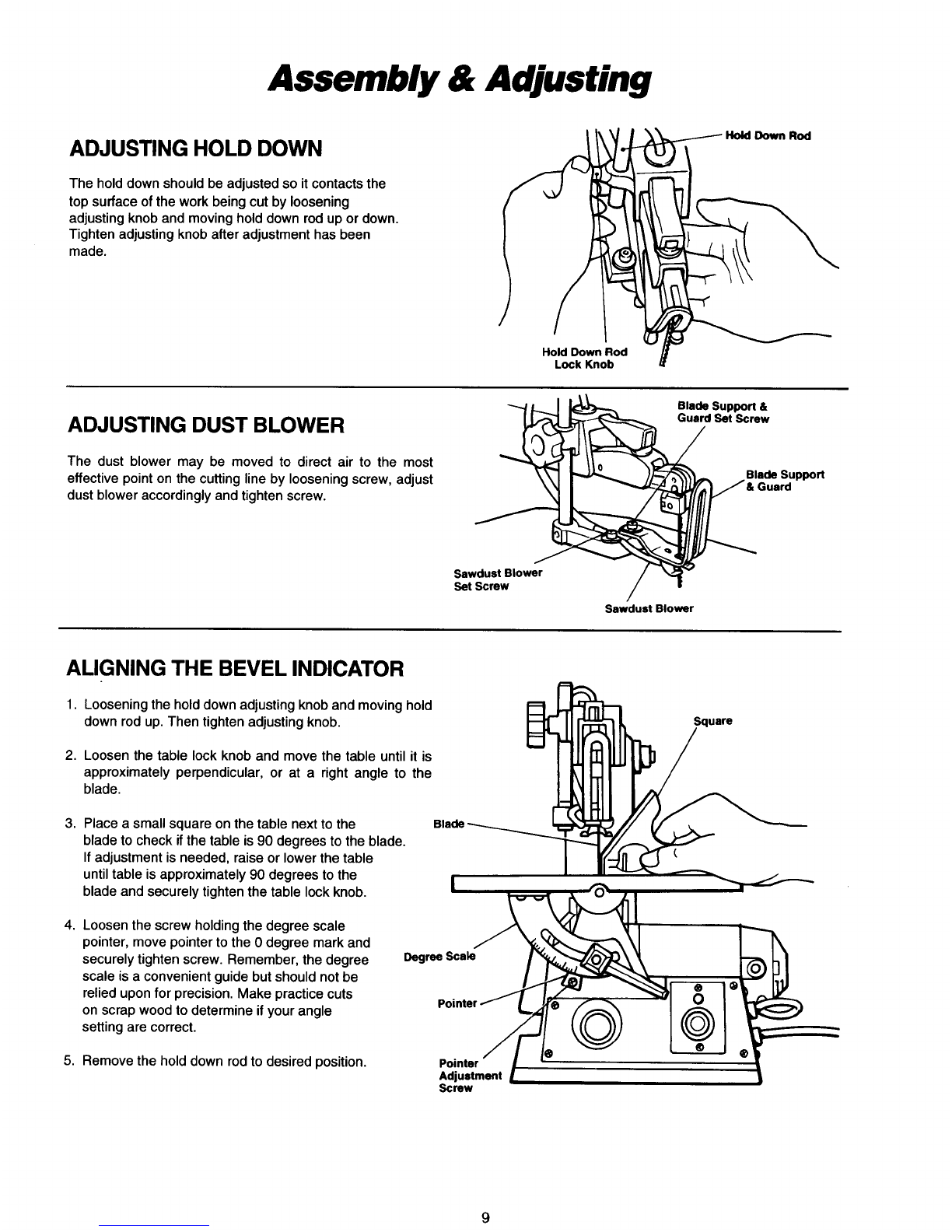
Adjusting Holddown
...........................
.9
Adjusting Dust Blower
..........................
.9
Aligning the Bevel Indicator
.......................
9
InstallingPin End Blade
.........................
10
Removing PlainEnd Blade
......................
11
On-Off Knob
.................................
12
BASIC SCROLL SAW OPERATION
..............
.13
Making InteriorScroll Cuts
......................
14
Before Each Use
..............................
14
Choice of Blade and Speed
......................
14
MAINTAININGYOUR SCROLL SAW..
............
.15
CONTENT PARTS
............................
.16
TROUBLE SHOOTING
.........................
.19
InstallingPlainEnd Blade
.......................
11
GeneralSafetyRules
1. Know Your PowerTool
Read and understand the owner's manual and labels
affixed
to
the
tool.
Learnitsapplication and limitations as
well as the specific potentialhazardspeculiar
to
this
tool.
This tool is equippedwith an approved 3-conductor cord
and a 3-prong grounding type plug
to
fit the proper
grounding type receptacle. The green conductor in the
cord isthe grounding wire. Neverconnectthegreenwire
to a liveterminal.
Cluttered areas and benches invite accidents. Floor
must not beslippery due
to
wax or sawdust.
Don't use power
tools
in damp or wet locations or ex-
pose them
to
rain. Keep work area well lighted. Provide
adequate surrounding work space.
Inworking order, and inadjustment and alignment.
Form a habit of checking
to
see that keys and adjusting
wrenches are removedfrom tool before turningit on.
All visitors should be kept a safe distance from work
area.
With padlocks, master switches, or by removing starter
keys.
9. Don't ForceTool
It
will
do the job betterand safer at the rate for which it
was designed.
Serious injury could occur
if
the tool is tipped or
if
the
cutting
tool
isaccidentally contacted.
Do not store materials above or nearthe tool such that it
is necessaryto standon thetool
to
reachthem.
11. Use Right Tool
Don't force tools or attachment
to
do a job it was not
designed for.
Do not wear loose clothing, gloves, neckties
or
jewelry
(ringswristwatches)
to
get caught inmovingparts. NON-
SLIP footwear is recommended.
Wear protectivehair covering
to
contain long hair,
Roll
longsleeves above the elbow.
2. Ground allTools
3. Keep Work Area Clean
4.
Avoid Dangerous Environment
5.
Keep Guards in Place
6. Remove Adjusting keysand Wrenches
7.
Keep Children Away
8.
MakeWorkshop Child Proof
10.
Never Stand on Tool
12. Wear Proper Apparel
2
13. Secure Work
Use clamps or a vise
to
hold work when practical.
It's
safer than using your hands and frees both hands
to
operate
tool.
Wear safety goggles (must comply with ANSIZ87.1) at
all times. Everyday eyeglasses only have impact
resistant lenses,they are NOT safety glasses. Also, use
face or dust mask
if
cutting operation is dusty, and ear
protectors (plugs or muffs) during extended periods or
operation.
Keep proper footingandbalanceat alltimes.
Beforefurther use of the
tool,
aguardor other partthat is
damaged should be carefully checked
to
ensure that it
will operate properly and perform its intendedfunction.
Check for alignment of movingparts, bindingof moving
parts, breakage of parts, mounting, and any other
conditions that may affect its operation.
A
guard or any
part that is damaged should be properly repaired or
replaced.
Consult the owner's manual for recommended acces-
sories. Follow the instructionsthat accompany the ac-
cessories. The use of improper accessories may cause
hazards.
Before servicing; when changing accessories such as
blades, bits, cutter, etc.
Feedwork into a blade or cutter against the directionof
rotation of the blade or cutter only.
Keep tools sharp and clean for best and safest
performance. Follow instructions for lubricating and
changingblades, bits, cutters, etc.
Makessure switchisin"OFF" positionbeforepluggingin
power cord.
Turn power
off.
Don't leave tool until it comes
to
a
complete stop.
14. Use Safety Goggles
15. Don'tOverreach
16. Check Damaged Parts
17. Use RecommendedAccessories
18. Disconnect Tools
19. Directionof Feed
20. MaintainTools with Care
21. Avoid Accidental Starting
22.
Never LeaveTool RunningUnattended