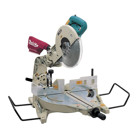
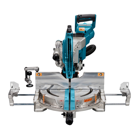
Makita LS1040 User manual

LS1040
LS1040S
LS1040F
LS1040FS
EN Compound Miter Saw INSTRUCTION MANUAL 8
UK Комбінована торцювальна
пила ІНСТРУКЦІЯ З
ЕКСПЛУАТАЦІЇ 17
PL Ukośnica INSTRUKCJA OBSŁUGI 27
RO Ferăstrău pentru tăieri oblice
combinate MANUAL DE INSTRUCŢIUNI 38
DE Kapp-und Gehrungssäge BEDIENUNGSANLEITUNG 48
HU Kombinált gérvágó HASZNÁLATI KÉZIKÖNYV 59
SK Zložená píla na zrezávanie NÁVOD NA OBSLUHU 69
CS Pokosová pila NÁVOD K OBSLUZE 79

1
2
3
12
34
1
ɸ9x 2
185 mm 219 mm
11
1
1
12
Fig.1
Fig.2
Fig.3
Fig.4
Fig.5
Fig.6
Fig.7
Fig.8
2

1
2
2
1
3
1
2
3
4
1
1
23
231
1
1
2
Fig.9
Fig.10
Fig.11
Fig.12
Fig.13
Fig.14
Fig.15
Fig.16
3

1
3
4
2
1
2
21 43
1
23
4
5
6
Fig.21
1
2
3
12
1
Fig.17
Fig.18
Fig.19
Fig.20
Fig.22
Fig.23
Fig.24
4

1
1
2
3
6
4
57
12
3
4
12
2
1
1
2
3
4
5
Fig.25
Fig.26
Fig.27
Fig.28
Fig.29
Fig.30
Fig.31
Fig.32
5

1
2
3
1
1
3
1
2
2
3
1
1
2
3
12
3
4
Fig.33
Fig.34
Fig.35
Fig.36
Fig.37
Fig.38
Fig.39
Fig.40
6

1
23
4
1
2
34
1
5
1
12
Fig.41
Fig.42
Fig.43
Fig.44
7

8ENGLISH
ENGLISH (Original instructions)
SPECIFICATIONS
Model LS1040 / LS1040S LS1040F / LS1040FS
Blade diameter 255 mm - 260 mm
Hole diameter For all countries other than
European countries
25.4 mm, 25 mm or 30 mm (Country specic)
For European countries 30 mm
Max. kerf thickness of the saw blade 3.2 mm
Max. Miter angle Left 45°, Right 52°
Max. Bevel angle Left 45°
No load speed 5,100 min-1
Dimensions (L x W x H) 530 mm x 476 mm x 532 mm
Net weight 11.8 kg 12.0 kg
Safety class /II
• Due to our continuing program of research and development, the specications herein are subject to change
without notice.
• Specications may differ from country to country.
• Weight according to EPTA-Procedure 01/2014
Max. Cutting capacities (H x W) with blade 260 mm in diameter
Bevel angle Miter angle
0° 45° (left and right)
0° 93 mm x 95 mm 93 mm x 67 mm
69 mm x 135 mm 69 mm x 95 mm
45° (left) 53 mm x 95 mm 49 mm x 67 mm
35 mm x 135 mm 35 mm x 94 mm
Symbols
The following show the symbols used for the equip-
ment. Be sure that you understand their meaning before
use.
Read instruction manual.
DOUBLE INSULATION
To avoid injury from ying debris, keep
holding the saw head down, after making
cuts, until the blade has come to a com-
plete stop.
Do not place hand or ngers close to the
blade.
For your safety, remove the chips, small
pieces, etc. from the table top before
operation.
Always set SUB-FENCE to left position
when performing left bevel cuts. Failure to
do so may cause serious injury to operator.
To loosen the bolt, turn it clockwise.
Only for EU countries
Do not dispose of electric equipment
together with household waste material!
In observance of the European Directive,
on Waste Electric and Electronic
Equipment and its implementation in
accordance with national law, electric
equipment that have reached the end of
their life must be collected separately and
returned to an environmentally compatible
recycling facility.
Intended use
The tool is intended for accurate straight and miter
cutting in wood. With appropriate saw blades, aluminum
can also be sawed.
Power supply
The tool should be connected only to a power supply of
the same voltage as indicated on the nameplate, and
can only be operated on single-phase AC supply. They
are double-insulated and can, therefore, also be used
from sockets without earth wire.

9ENGLISH
For public low-voltage distribution
systems of between 220 V and 250 V
For Model LS1040
Switching operations of electric apparatus cause voltage
uctuations. The operation of this device under unfavor-
able mains conditions can have adverse effects to the
operation of other equipment. With a mains impedance
equal or less than 0.29 Ohms it can be presumed that
there will be no negative effects. The mains socket used
for this device must be protected with a fuse or protective
circuit breaker having slow tripping characteristics.
For Model LS1040F
Switching operations of electric apparatus cause voltage
uctuations. The operation of this device under unfavor-
able mains conditions can have adverse effects to the
operation of other equipment. With a mains impedance
equal or less than 0.34 Ohms it can be presumed that
there will be no negative effects. The mains socket used
for this device must be protected with a fuse or protec-
tive circuit breaker having slow tripping characteristics.
Noise
The typical A-weighted noise level determined accord-
ing to EN62841-3-9:
Sound pressure level (LpA) : 91 dB(A)
Sound power level (LWA) : 101 dB (A)
Uncertainty (K) : 3 dB(A)
NOTE:
The declared noise emission value(s) has been
measured in accordance with a standard test method
and may be used for comparing one tool with another.
NOTE:
The declared noise emission value(s) may
also be used in a preliminary assessment of exposure.
WARNING: Wear ear protection.
WARNING: The noise emission during actual
use of the power tool can differ from the declared
value(s) depending on the ways in which the
tool is used especially what kind of workpiece is
processed.
WARNING: Be sure to identify safety mea-
sures to protect the operator that are based on an
estimation of exposure in the actual conditions of
use (taking account of all parts of the operating
cycle such as the times when the tool is switched
off and when it is running idle in addition to the
trigger time).
Vibration
The vibration total value (tri-axial vector sum) deter-
mined according to EN62841-3-9:
Vibration emission (ah) : 2.5 m/s2or less
Uncertainty (K) : 1.5 m/s2
NOTE: The declared vibration total value(s) has been
measured in accordance with a standard test method
and may be used for comparing one tool with another.
NOTE: The declared vibration total value(s) may also
be used in a preliminary assessment of exposure.
WARNING: The vibration emission during
actual use of the power tool can differ from the
declared value(s) depending on the ways in which
the tool is used especially what kind of workpiece
is processed.
WARNING: Be sure to identify safety mea-
sures to protect the operator that are based on an
estimation of exposure in the actual conditions of
use (taking account of all parts of the operating
cycle such as the times when the tool is switched
off and when it is running idle in addition to the
trigger time).
EC Declaration of Conformity
For European countries only
The EC declaration of conformity is included as Annex A
to this instruction manual.
General power tool safety warnings
WARNING: Read all safety warnings, instruc-
tions, illustrations and specications provided
with this power tool. Failure to follow all instructions
listed below may result in electric shock, re and/or
serious injury.
Save all warnings and instruc-
tions for future reference.
The term "power tool" in the warnings refers to your
mains-operated (corded) power tool or battery-operated
(cordless) power tool.
Safety instructions for mitre saws
1. Mitre saws are intended to cut wood or wood-
like products, they cannot be used with abra-
sive cut-off wheels for cutting ferrous material
such as bars, rods, studs, etc. Abrasive dust
causes moving parts such as the lower guard to
jam. Sparks from abrasive cutting will burn the
lower guard, the kerf insert and other plastic parts.
2. Use clamps to support the workpiece when-
ever possible. If supporting the workpiece
by hand, you must always keep your hand at
least 100 mm from either side of the saw blade.
Do not use this saw to cut pieces that are too
small to be securely clamped or held by hand.
If your hand is placed too close to the saw blade,
there is an increased risk of injury from blade
contact.
3. The workpiece must be stationary and
clamped or held against both the fence and the
table. Do not feed the workpiece into the blade
or cut "freehand" in any way. Unrestrained
or moving workpieces could be thrown at high
speeds, causing injury.
4. Never cross your hand over the intended line
of cutting either in front or behind the saw
blade. Supporting the workpiece "cross handed"
i.e. holding the workpiece to the right of the saw
blade with your left hand or vice versa is very
dangerous.

10 ENGLISH
► Fig.1
5. Do not reach behind the fence with either hand
closer than 100 mm from either side of the saw
blade, to remove wood scraps, or for any other
reason while the blade is spinning. The proxim-
ity of the spinning saw blade to your hand may not
be obvious and you may be seriously injured.
6. Inspect your workpiece before cutting. If the
workpiece is bowed or warped, clamp it with
the outside bowed face toward the fence.
Always make certain that there is no gap
between the workpiece, fence and table along
the line of the cut. Bent or warped workpieces
can twist or shift and may cause binding on the
spinning saw blade while cutting. There should be
no nails or foreign objects in the workpiece.
7.
Do not use the saw until the table is clear of all tools,
wood scraps, etc., except for the workpiece. Small
debris or loose pieces of wood or other objects that con-
tact the revolving blade can be thrown with high speed.
8.
Cut only one workpiece at a time. Stacked multiple
workpieces cannot be adequately clamped or braced
and may bind on the blade or shift during cutting.
9.
Ensure the mitre saw is mounted or placed on a level,
rm work surface before use. A level and rm work sur-
face reduces the risk of the mitre saw becoming unstable.
10.
Plan your work. Every time you change the bevel
or mitre angle setting, make sure the adjustable
fence is set correctly to support the workpiece
and will not interfere with the blade or the guard-
ing system. Without turning the tool "ON" and with
no workpiece on the table, move the saw blade
through a complete simulated cut to assure there will
be no interference or danger of cutting the fence.
11. Provide adequate support such as table exten-
sions, saw horses, etc. for a workpiece that is
wider or longer than the table top. Workpieces
longer or wider than the mitre saw table can tip
if not securely supported. If the cut-off piece or
workpiece tips, it can lift the lower guard or be
thrown by the spinning blade.
12.
Do not use another person as a substitute for a
table extension or as additional support. Unstable
support for the workpiece can cause the blade to bind
or the workpiece to shift during the cutting operation
pulling you and the helper into the spinning blade.
13.
The cut-off piece must not be jammed or pressed
by any means against the spinning saw blade. If
conned, i.e. using length stops, the cut-off piece could
get wedged against the blade and thrown violently.
14. Always use a clamp or a xture designed to
properly support round material such as rods
or tubing. Rods have a tendency to roll while
being cut, causing the blade to "bite" and pull the
work with your hand into the blade.
15. Let the blade reach full speed before contact-
ing the workpiece. This will reduce the risk of the
workpiece being thrown.
16. If the workpiece or blade becomes jammed,
turn the mitre saw off. Wait for all moving
parts to stop and disconnect the plug from
the power source and/or remove the battery
pack. Then work to free the jammed material.
Continued sawing with a jammed workpiece could
cause loss of control or damage to the mitre saw.
17. After nishing the cut, release the switch,
hold the saw head down and wait for the blade
to stop before removing the cut-off piece.
Reaching with your hand near the coasting blade
is dangerous.
18. Hold the handle rmly when making an incom-
plete cut or when releasing the switch before
the saw head is completely in the down posi-
tion. The braking action of the saw may cause
the saw head to be suddenly pulled downward,
causing a risk of injury.
19. Only use the saw blade with the diameter that
is marked on the tool or specied in the man-
ual. Use of an incorrectly sized blade may affect
the proper guarding of the blade or guard opera-
tion which could result in serious personal injury.
20. Only use the saw blades that are marked with
a speed equal or higher than the speed marked
on the tool.
21. Do not use the saw to cut other than wood,
aluminum or similar materials.
22. (For European countries only)
Always use the blade which conforms to
EN847-1.
Additional instructions
1. Make workshop kid proof with padlocks.
2. Never stand on the tool. Serious injury could
occur if the tool is tipped or if the cutting tool is
unintentionally contacted.
3. Never leave the tool running unattended. Turn
the power off. Do not leave tool until it comes
to a complete stop.
4. Do not operate saw without guards in place.
Check blade guard for proper closing before
each use. Do not operate saw if blade guard
does not move freely and close instantly.
Never clamp or tie the blade guard into the
open position.
5. Keep hands out of path of saw blade. Avoid
contact with any coasting blade. It can still
cause severe injury.
6. Always secure all moving portions before
carrying the tool.
7. Stopper pin which locks the cutter head down
is for carrying and storage purposes only and
not for any cutting operations.
8. Check the blade carefully for cracks or dam-
age before operation. Replace cracked or dam-
aged blade immediately. Gum and wood pitch
hardened on blades slows saw and increases
potential for kickback. Keep blade clean by
rst removing it from tool, then cleaning it with
gum and pitch remover, hot water or kerosene.
Never use gasoline to clean blade.
9. Use only anges specied for this tool.
10. Be careful not to damage the arbor, anges
(especially the installing surface) or bolt.
Damage to these parts could result in blade
breakage.
11. Make sure that the turn base is properly
secured so it will not move during operation.
Use the holes in the base to fasten the saw to a
stable work platform or bench. NEVER use tool
where operator positioning would be awkward.
11 ENGLISH
12. Make sure the shaft lock is released before the
switch is turned on.
13. Be sure that the blade does not contact the
turn base in the lowest position.
14. Hold the handle rmly. Be aware that the saw
moves up or down slightly during start-up and
stopping.
15. Make sure the blade is not contacting the
workpiece before the switch is turned on.
16. Before using the tool on an actual workpiece,
let it run for a while. Watch for vibration or
wobbling that could indicate poor installation
or a poorly balanced blade.
17. Stop operation immediately if you notice any-
thing abnormal.
18. Do not attempt to lock the trigger in the "ON"
position.
19. Always use accessories recommended in this
manual. Use of improper accessories such as
abrasive wheels may cause an injury.
20. Some material contains chemicals which may
be toxic. Take caution to prevent dust inhala-
tion and skin contact. Follow material supplier
safety data.
Additional safety rules for the laser
1. LASER RADIATION, DO NOT STARE INTO THE
BEAM OR VIEW DIRECTLY WITH OPTICAL
INSTRUMENTS, CLASS 2M LASER PRODUCT.
SAVE THESE INSTRUCTIONS.
WARNING: DO NOT let comfort or familiarity
with product (gained from repeated use) replace
strict adherence to safety rules for the subject
product. MISUSE or failure to follow the safety
rules stated in this instruction manual may cause
serious personal injury.
INSTALLATION
Installing auxiliary plate
► Fig.2: 1. Auxiliary plate 2. Hex bolt 3. Base
► Fig.3: 1. Auxiliary plate 2. Base 3. Hex bolt 4. Nut
Installing the auxiliary plate using the notch in the tool's
base and secure it by tightening the hex bolt.
Bench mounting
When the tool is shipped, the handle is locked in the
lowered position by the stopper pin. Release the stop-
per pin by lowering the handle slightly and pulling the
stopper pin.
► Fig.4: 1. Stopper pin
This tool should be bolted with two bolts to a level and
stable surface using the bolt holes provided in the tool's
base. This will help prevent tipping and possible per-
sonal injury.
► Fig.5: 1. Bolt
FUNCTIONAL
DESCRIPTION
CAUTION:
• Always be sure that the tool is switched off and
unplugged before adjusting or checking function
on the tool.
Blade guard
► Fig.6: 1. Blade guard
When lowering the handle, the blade guard rises auto-
matically. The guard is spring loaded so it returns to
its original position when the cut is completed and the
handle is raised. NEVER DEFEAT OR REMOVE THE
BLADE GUARD OR THE SPRING WHICH ATTACHES
TO THE GUARD.
In the interest of your personal safety, always maintain
the blade guard in good condition. Any irregular opera-
tion of the blade guard should be corrected immediately.
Check to assure spring loaded return action of guard.
NEVER USE THE TOOL IF THE BLADE GUARD OR
SPRING ARE DAMAGED, FAULTY OR REMOVED.
DOING SO IS HIGHLY DANGEROUS AND CAN
CAUSE SERIOUS PERSONAL INJURY.
If the see-through blade guard becomes dirty, or saw-
dust adheres to it in such a way that the blade is no lon-
ger easily visible, unplug the saw and clean the guard
carefully with a damp cloth. Do not use solvents or any
petroleum-based cleaners on the plastic guard.
If the blade guard is especially dirty and vision through
the guard is impaired, use the supplied socket wrench
to loosen the hex bolt holding the center cover. Loosen
the hex bolt by turning it counterclockwise and raise
the blade guard and center cover. With the blade guard
so positioned, cleaning can be more completely and
efciently accomplished. When cleaning is complete,
reverse procedure above and secure bolt. Do not
remove spring holding blade guard. If guard becomes
discolored through age or UV light exposure, contact
a Makita service center for a new guard. DO NOT
DEFEAT OR REMOVE GUARD.
► Fig.7: 1. Blade guard
Kerf board
► Fig.8: 1. Kerf board 2. Turn base
This tool is provided with the kerf board in the turn base
to minimize tearing on the exit side of a cut. If the kerf
groove has not yet been cut in the kerf board by the
factory, you should cut the groove before actually using
the tool to cut a workpiece. Switch on the tool and lower
the blade gently to cut a groove in the kerf board.

12 ENGLISH
Maintaining maximum cutting
capacity
► Fig.9: 1. Socket wrench 2. Adjusting bolt
► Fig.10: 1. Top surface of turn base 2. Periphery of
blade 3. Guide fence
This tool is factory adjusted to provide the maximum
cutting capacity for a 260 mm saw blade.
When installing a new blade, always check the lower
limit position of the blade and if necessary, adjust it as
follows:
First, unplug the tool. Lower the handle completely.
Use the socket wrench to turn the adjusting bolt until
the periphery of the blade extends slightly below the
top surface of the turn base at the point where the front
face of the guide fence meets the top surface of the turn
base.
With the tool unplugged, rotate the blade by hand while
holding the handle all the way down to be sure that
the blade does not contact any part of the lower base.
Re-adjust slightly, if necessary.
CAUTION:
• After installing a new blade, always be sure that
the blade does not contact any part of the lower
base when the handle is lowered completely.
Always do this with the tool unplugged.
Adjusting the miter angle
► Fig.11: 1. Pointer 2. Lock lever 3. Grip 4. Miter
scale
Loosen the grip by turning counterclockwise. Turn the
turn base while pressing down the lock lever. When you
have moved the grip to the position where the pointer
points to the desired angle on the miter scale, securely
tighten the grip clockwise.
CAUTION:
• When turning the turn base, be sure to raise the
handle fully.
• After changing the miter angle, always secure
the turn base by tightening the grip rmly.
Adjusting the bevel angle
► Fig.12: 1. Lever
► Fig.13: 1. Lever 2. Bevel scale 3. Pointer
To adjust the bevel angle, loosen the lever at the rear of
the tool counterclockwise.
Push the handle to the left to tilt the saw blade until the
pointer points to the desired angle on the bevel scale.
Then tighten the lever clockwise rmly to secure the
arm.
CAUTION:
• When tilting the saw blade, be sure to raise the
handle fully.
• After changing the bevel angle, always secure
the arm by tightening the lever clockwise.
Switch action
WARNING: Before plugging in the tool,
always check to see that the switch trigger actu-
ates properly and returns to the "OFF" position
when released. Do not pull the switch trigger hard
without pressing in the lock-off button. This can
cause switch breakage. Operating a tool with a
switch that does not actuate properly can lead to loss
of control and serious personal injury.
WARNING: NEVER
use tool without a fully oper-
ative switch trigger. Any tool with an inoperative switch
is HIGHLY DANGEROUS and must be repaired before
further usage or serious personal injury may occur.
WARNING: NEVER defeat the lock-off button
by taping down or some other means. A switch with
a negated lock-off button may result in unintentional
operation and serious personal injury.
WARNING: NEVER use the tool if it runs when
you simply pull the switch trigger without press-
ing the lock-off button. A switch in need of repair
may result in unintentional operation and serious
personal injury. Return tool to a Makita service center
for proper repairs BEFORE further usage.
► Fig.14: 1. Switch trigger 2. Lock-off button 3. Hole
for padlock
To prevent the switch trigger from being accidentally
pulled, a lock-off button is provided. To start the tool,
press in the lock-off button and pull the switch trigger.
Release the switch trigger to stop.
A hole is provided in the switch trigger for insertion of a
padlock to lock the tool off.
WARNING: Do not use a lock with a shank
or cable any smaller than 6.35 mm in diameter. A
smaller shank or cable may not properly lock the tool
in the off position and unintentional operation may
occur resulting in serious personal injury.
Lighting up the lamps
Only for model LS1040F / LS1040FS
► Fig.15: 1. Light switch
CAUTION:
•
This is not a rainproof light. Do not wash the light
in water or use it in a rain or a wet area. Such a
conduct can cause an electric shock and fume.
• Do not touch the lens of the light, as it is very hot
while it is lighted or shortly after it is turned off.
This may cause a burn to a human body.
• Do not apply impact to the light, which may
cause damage or shorted service time to it.
• Do not keep casting the beam of the light to your
eyes. This can cause your eyes to be hurt.
• Do not cover the light with clothes, carton, card-
board or similar objects while it is lighted, which
can cause a re or an ignition.
Push the upper position of the switch for turning on the
light and the lower position for off.
Move the light to shift an area of lighting.
► Fig.16: 1. Light 2. Light switch

13 ENGLISH
NOTE:
• Use a dry cloth to wipe the dirt off the lens of
lamp. Be careful not to scratch the lens of light,
or it may lower the illumination.
ASSEMBLY
CAUTION:
• Always be sure that the tool is switched off and
unplugged before carrying out any work on the
tool.
Installing or removing saw blade
CAUTION: Always be sure that the tool is
switched off and unplugged before installing or
removing the blade.
CAUTION: Use only the Makita socket wrench
provided to install or remove the blade. Failure to
do so may result in overtightening or insufcient
tightening of the hex bolt. This could cause an
injury.
When removing or installing the blade, keep the handle
in the raised position.
To remove the blade, use the socket wrench to loosen
the hex bolt holding the center cover by turning it coun-
terclockwise. Raise the blade guard and center cover.
► Fig.17: 1. Center cover 2. Socket wrench 3. Hex
bolt 4. Blade guard
Press the shaft lock to lock the spindle and use the
wrench to loosen the hex bolt clockwise. Then remove
the hex bolt, outer ange and blade.
► Fig.18: 1. Socket wrench 2. Shaft lock
To install the blade, mount it carefully onto the spindle,
making sure that the direction of the arrow on the sur-
face of the blade matches the direction of the arrow on
the blade case.
► Fig.19: 1. Blade case 2. Arrow 3. Saw blade
4. Arrow
Install the ange and hex bolt, and then use the socket
wrench to tighten the hex bolt (left-handed) securely
counterclockwise while pressing the shaft lock.
► Fig.20: 1. Spindle 2. Flange 3. Saw blade 4. Flange
5. Hex bolt 6. Ring
CAUTION: The ring 25.4 mm or 30 mm in
outer diameter is factory-installed onto the spin-
dle. Before mounting the blade onto the spindle,
always be sure that the correct ring for the arbor
hole of the blade you intend to use is installed
onto the spindle.
Return the blade guard and center cover to its original
position. Then tighten the hex bolt clockwise to secure
the center cover. Lower the handle to make sure that
the blade guard moves properly. Make sure shaft lock
has released spindle before making cut.
Connecting a vacuum cleaner
When you wish to perform clean cutting operation,
connect a Makita vacuum cleaner.
► Fig.21
Dust bag
► Fig.22: 1. Dust nozzle 2. Dust bag 3. Fastener
The use of the dust bag makes cutting operations clean
and dust collection easy. To attach the dust bag, t it
onto the dust nozzle.
When the dust bag is about half full, remove the dust
bag from the tool and pull the fastener out. Empty
the dust bag of its contents, tapping it lightly so as to
remove particles adhering to the insides which might
hamper further collection.
Securing workpiece
WARNING:
• It is extremely important to always secure the
workpiece properly and tightly with the vise.
Failure to do so can cause the tool to be dam-
aged and/or the workpiece to be destroyed.
PERSONAL INJURY MAY ALSO RESULT. Also,
after a cutting operation, DO NOT raise the
blade until the blade has come to a complete
stop.
CAUTION:
• When cutting long workpieces, use supports
that are as high as the top surface level of the
turn base. Do not rely solely on the vertical vise
and/or horizontal vise to secure the workpiece.
Thin material tends to sag. Support workpiece
over its entire length to avoid blade pinch and
possible KICKBACK.
► Fig.23: 1. Support 2. Turn base
Sub-fence
► Fig.24: 1. Sub-fence
This tool is equipped with the sub-fence. It should be
positioned as shown in the gure.
CAUTION:
• When performing left bevel cuts, ip the fence
over to the left position as shown in the gure.
Otherwise, it will contact the blade or a part of
the tool, causing possible serious injury to the
operator.
► Fig.25: 1. Sub-fence
Vertical vise
► Fig.26: 1. Vise arm 2. Vise rod 3. Guide fence
4. Holder 5. Holder assembly 6. Vise knob
7. Screw
The vertical vise can be installed in two positions on
either the left or right side of the guide fence or the
holder assembly (optional accessory). Insert the vise
rod into the hole in the guide fence or the holder assem-
bly and tighten the screw to secure the vise rod.

14 ENGLISH
Position the vise arm according to the thickness and
shape of the workpiece and secure the vise arm by
tightening the screw. If the screw to secure the vise arm
contacts the guide fence, install the screw on the oppo-
site side of vise arm. Make sure that no part of the tool
contacts the vise when lowering the handle all the way.
If some part contacts the vise, re-position the vise.
Press the workpiece at against the guide fence and the
turn base. Position the workpiece at the desired cutting
position and secure it rmly by tightening the vise knob.
CAUTION:
• The workpiece must be secured rmly against
the turn base and guide fence with the vise
during all operations.
Horizontal vise (optional accessory)
► Fig.27: 1. Vise knob 2. Projection 3. Vise shaft
4. Base
The horizontal vise can be installed on either the left or
right side of the base. When performing 15° or greater
miter cuts, install the horizontal vise on the side oppo-
site the direction in which the turn base is to be turned.
By turning the vise knob counterclockwise, the screw
is released and the vise shaft can be moved rapidly in
and out. By turning the vise knob clockwise, the screw
remains secured. To grip the workpiece, turn the vise
knob gently clockwise until the projection reaches its
topmost position, then fasten securely. If the vise knob
is forced in or pulled out while being turned clockwise,
the projection may stop at an angle. In this case, turn
the vise knob back counterclockwise until the screw is
released, before turning again gently clockwise.
The maximum width of the workpiece which can be
secured by the horizontal vise is 130 mm.
CAUTION:
• Grip the workpiece only when the projection is
at the topmost position. Failure to do so may
result in insufcient securing of the workpiece.
This could cause the workpiece to be thrown,
cause damage to the blade or cause the loss
of control, which can result in PERSONAL
INJURY.
Holders and holder assembly
(optional accessories)
► Fig.28: 1. Holder 2. Holder assembly
The holders and the holder assembly can be installed
on either side as a convenient means of supporting
workpieces horizontally. Install them as shown in the
gure. Then tighten the screws rmly to secure the
holders and the holder assembly.
When cutting long workpieces, use the holder-rod
assembly (optional accessory). It consists of two holder
assemblies and two rods 12.
► Fig.29: 1. Holder assembly 2. Rod 12
CAUTION:
• Always support long workpieces level with the
top surface of the turn base for accurate cuts
and to prevent dangerous loss of control of the
tool.
OPERATION
CAUTION:
• Before use, be sure to release the handle from
the lowered position by pulling the stopper pin.
• Make sure the blade is not contacting the work-
piece, etc. before the switch is turned on.
•
Do not apply excessive pressure on the handle when cut-
ting. Too much force may result in overload of the motor
and/or decreased cutting efciency. Push down handle
with only as much force as is necessary for smooth
cutting and without signicant decrease in blade speed.
• Gently press down the handle to perform the
cut. If the handle is pressed down with force or if
lateral force is applied, the blade will vibrate and
leave a mark (saw mark) in the workpiece and
the precision of the cut will be impaired.
Press cutting
► Fig.30
Secure the workpiece with the vise. Switch on the tool with-
out the blade making any contact and wait until the blade
attains full speed before lowering. Then gently lower the
handle to the fully lowered position to cut the workpiece.
When the cut is completed, switch off the tool and WAIT
UNTIL THE BLADE HAS COME TO A COMPLETE STOP
before returning the blade to its fully elevated position.
Miter cutting
Refer to the previously covered "Adjusting the miter angle".
Bevel cut
► Fig.31
Loosen the lever and tilt the saw blade to set the bevel angle
(Refer to the previously covered "Adjusting the bevel angle").
Be sure to retighten the lever rmly to secure the selected
bevel angle safely. Secure the workpiece with a vise. Switch
on the tool without the blade making any contact and wait until
the blade attains full speed. Then gently lower the handle to
the fully lowered position while applying pressure in parallel
with the blade. When the cut is completed, switch off the tool
and WAIT UNTIL THE BLADE HAS COME TO A COMPLETE
STOP before returning the blade to its fully elevated position.
CAUTION:
• Always be sure that the blade will move down to
bevel direction during a bevel cut. Keep hands
out of path of saw blade.
•
During a bevel cut, it may create a condition
whereby the piece cut off will come to rest against
the side of the blade. If the blade is raised while
the blade is still rotating, this piece may be caught
by the blade, causing fragments to be scattered
which is dangerous. The blade should be raised
ONLY after the blade has come to a complete stop.
•
When pressing the handle down, apply pressure
parallel to the blade. If the pressure is not parallel to
the blade during a cut, the angle of the blade might be
shifted and the precision of the cut will be impaired.
• Always set the sub-fence to the left position
when performing left bevel cuts.

15 ENGLISH
Compound cutting
Compound cutting is the process in which a bevel
angle is made at the same time in which a miter
angle is being cut on a workpiece. Compound cut-
ting can be performed at angle shown in the table.
Miter angle
Bevel angle
Left and Right 0 - 45
45
When performing compound cutting, refer to
"Press cutting", "Miter cutting" and "Bevel cut"
explanations.
Cutting aluminum extrusion
► Fig.32: 1. Vise 2. Spacer block 3. Guide fence
4. Aluminum extrusion 5. Spacer block
When securing aluminum extrusions, use spacer
blocks or pieces of scrap as shown in the gure to
prevent deformation of the aluminum. Use a cutting
lubricant when cutting the aluminum extrusion to pre-
vent build-up of the aluminum material on the blade.
CAUTION:
• Never attempt to cut thick or round aluminum
extrusions. Thick aluminum extrusions may
come loose during operation and round alumi-
num extrusions cannot be secured rmly with
this tool.
Wood facing
Use of wood facing helps to assure splinter-free
cuts in workpieces. Attach a wood facing to the
guide fence using the holes in the guide fence.
See the gure concerning the dimensions for a
suggested wood facing.
Over 10mm (3/8") Over 460mm (18-1/8")
11
90mm
(3-9/16")
25mm
(1")
90mm
(3-9/16")
107mm
(4-7/32")
90mm
(3-9/16")
107mm
(4-7/32")
1. Hole
CAUTION:
• Use straight wood of even thickness as the
wood facing.
• Use screws to attach the wood facing to the
guide fence. The screws should be installed so
that the screw heads are below the surface of
the wood facing.
• When the wood facing is attached, do not turn
the turn base with the handle lowered. The
blade and/or the wood facing will be damaged.
Cutting repetitive lengths
► Fig.33: 1. Set plate 2. Holder 3. Screw
When cutting several pieces of stock to the same
length, ranging from 240 mm to 400 mm, use of
the set plate (optional accessory) will facilitate
more efcient operation. Install the set plate on the
holder (optional accessory) as shown in the gure.
Align the cutting line on your workpiece with either
the left or right side of the groove in the kerf board,
and while holding the workpiece from moving,
move the set plate ush against the end of the
workpiece. Then secure the set plate with the
screw. When the set plate is not used, loosen the
screw and turn the set plate out of the way.
NOTE:
• Use of the holder-rod assembly (optional acces-
sory) allows cutting repetitive lengths up to
2,200 mm (7.2 ft.) approximately.
Carrying tool
► Fig.34: 1. Stopper pin
Make sure that the tool is unplugged. Secure the blade
at 0° bevel angle and the turn base at left miter angle
fully. Lower the handle fully and lock it in the lowered
position by pushing in the stopper pin.
Carry the tool by carrying grip as shown in the gure. If
you remove the holders, dust bag, etc., you can carry
the tool more easily.
► Fig.35
CAUTION:
• Always secure all moving portions before carry-
ing the tool.
• Stopper pin is for carrying and storage purposes
only and not for any cutting operations.
MAINTENANCE
CAUTION:
• Always be sure that the tool is switched off and
unplugged before attempting to perform inspec-
tion or maintenance.
•
Never use gasoline, benzine, thinner, alcohol or the
like. Discoloration, deformation or cracks may result.
WARNING:
• Always be sure that the blade is sharp and clean
for the best and safest performance.
Adjusting the cutting angle
This tool is carefully adjusted and aligned at the factory,
but rough handling may have affected the alignment. If
your tool is not aligned properly, perform the following:
Miter angle
► Fig.36: 1. Hex bolt
Loosen the grip which secures the turn base. Turn
the turn base so that the pointer points to 0° on the
miter scale. Tighten the grip and loosen the hex bolts
securing the guide fence using the socket wrench.
Lower the handle fully and lock it in the lowered position
by pushing in the stopper pin. Square the side of the
blade with the face of the guide fence using a triangular
rule, try-square, etc. Then securely tighten the hex bolts
on the guide fence in the order from the right side.
► Fig.37: 1. Triangular rule 2. Grip 3. Guide fence

16 ENGLISH
Bevel angle
0° bevel angle
► Fig.38: 1. Turn base 2. Lever 3. 0° adjusting bolt
Lower the handle fully and lock it in the lowered position by push-
ing in the stopper pin. Loosen the lever at the rear of the tool.
Turn the 0° bevel angle adjusting bolt on the right side
of the turn base two or three revolutions clockwise to tilt
the blade to the right.
Carefully square the side of the blade with the top
surface of the turn base using the triangular rule, try-
square, etc. by turning the 0° bevel angle adjusting bolt
counterclockwise. Then tighten the lever securely.
► Fig.39: 1. Triangular rule 2. Saw blade 3. Top sur-
face of turn base
Make sure that the pointer on the turn base point to 0°
on the bevel scale on the arm. If it does not point to 0°,
loosen the screw which secures the pointer and adjust
the pointer so that it will point to 0°.
► Fig.40:
1. Arm 2. Bevel scale 3. Pointer 4. Turn base
45° bevel angle
► Fig.41: 1. Lever 2. Arm 3. Pointer 4. 45° bevel angle
adjusting bolt
Adjust the 45° bevel angle only after performing 0° bevel angle
adjustment. To adjust left 45° bevel angle, loosen the lever and
tilt the blade to the left fully. Make sure that the pointer on the
arm points to 45° on the bevel scale on the arm holder. If the
pointer does not point to 45°, turn the 45° bevel angle adjusting
bolt on the left side of the arm until the pointer points to 45°.
Replacing uorescent tube
Only for model LS1040F / LS1040FS
► Fig.42: 1. Pull out 2. Push 3. Lamp box 4. Screws
5. Fluorescent tube
CAUTION:
•
Always be sure that the tool is switched off and
unplugged before replacing the uorescent tube.
•
Do not apply force, impact or scratch to a uorescent
tube, which can cause a glass of the uorescent tube to
be broken resulting in a injury to you or your bystanders.
• Leave the orescent tube for a while immedi-
ately after a use of it and then replace it. If not.
You may burn yourself.
Remove screws, which secure Lamp Box for the light.
Pull out the Lamp Box keeping pushing lightly the upper
position of it as illustrated on the left.
Pull out the uorescent tube and then replace it with
Makita original new one.
Replacing carbon brushes
► Fig.43: 1. Limit mark
Remove and check the carbon brushes regularly.
Replace when they wear down to the limit mark. Keep
the carbon brushes clean and free to slip in the holders.
Both carbon brushes should be replaced at the same
time. Use only identical carbon brushes.
Use a screwdriver to remove the brush holder caps.
Take out the worn carbon brushes, insert the new ones
and secure the brush holder caps.
► Fig.44: 1. Screwdriver 2. Brush holder cap
After use
• After use, wipe off chips and dust adhering to the
tool with a cloth or the like. Keep the blade guard
clean according to the directions in the previously
covered section titled "Blade guard". Lubricate the
sliding portions with machine oil to prevent rust.
To maintain product SAFETY and RELIABILITY, repairs,
any other maintenance or adjustment should be per-
formed by Makita Authorized Service Centers, always
using Makita replacement parts.
OPTIONAL
ACCESSORIES
WARNING: These Makita accessories or
attachments are recommended for use with your
Makita tool specied in this manual. The use of
any other accessories or attachments may result in
serious personal injury.
WARNING: Only use the Makita accessory
or attachment for its stated purpose. Misuse of
an accessory or attachment may result in serious
personal injury.
If you need any assistance for more details regard-
ing these accessories, ask your local Makita Service
Center.
• Steel & Carbide-tipped saw blade
(Refer to our website or contact your local Makita
dealer for the correct saw blades to be used for
the material to be cut.)
• Auxiliary plate
• Vise assembly (Horizontal vise)
• Vertical vise
• Socket wrench
• Holder set
• Holder assembly
• Holder rod assembly
• Set plate
• Dust bag
• Triangular rule
• Fluorescent tube
NOTE:
• Some items in the list may be included in the
tool package as standard accessories. They
may differ from country to country.

17 УКРАЇНСЬКА
УКРАЇНСЬКА (Оригінальні вказівки)
ТЕХНІЧНІ ХАРАКТЕРИСТИКИ
Модель LS1040 / LS1040S LS1040F / LS1040FS
Діаметр диска 255 мм – 260 мм
Діаметр отвору
Для всіх країн, крім європейських
25,4 мм, 25 мм або 30 мм (залежно від країни)
Для європейських країн 30 мм
Макс. товщина пропилу диска пили 3,2 мм
Макс. косий кут Лівий 45°, правий 52°
Макс. кут нахилу Лівий 45°
Швидкість без навантаження 5100 хв-1
Розміри (Д × Ш × В) 530 мм × 476 мм × 532 мм
Маса нетто 11,8 кг 12,0 кг
Клас безпеки /II
• Оскільки наша програма наукових досліджень і розробок триває безперервно, наведені тут технічні
характеристики можуть бути змінені без попередження.
• У різних країнах технічні характеристики можуть бути різними.
• Маса відповідно до EPTA-Procedure 01/2014
Макс. розміри розрізуваної деталі (В × Ш) із диском діаметром 260 мм
Кут нахилу Кут різання
0° 45° (лівий і правий)
0° 93 мм × 95 мм 93 мм × 67 мм
69 мм × 135 мм 69 мм × 95 мм
45° (лівий) 53 мм × 95 мм 49 мм × 67 мм
35 мм × 135 мм 35 мм × 94 мм
Символи
Далі наведені символи, які застосовуються для
позначення обладнання. Перед користуванням
переконайтеся, що Ви розумієте їхнє значення.
Прочитайте дану інструкцію.
ПОДВІЙНА ІЗОЛЯЦІЯ
Для того, щоб запобігти поранення унас-
лідок розлітання сміття, слід притиснути
голівку пили, після різання, доки диск
повністю не зупиниться.
Тримайте руки або пальці на відстані
від диска.
Перед початком роботи заберіть тирсу,
маленькі частки і т.д. зі столу для вашої
безпеки.
Під час виконання прорізів з лівим
нахилом, завжди слід встановлювати
НАПРЯМНУ ПІДПОРУ в ліве положення.
Невиконання цієї умови може призвести
до серйозного поранення оператора.
Для того, щоб відпустити болт поверніть
його за годинниковою стрілкою.
Тільки для країн ЄС
Не викидайте електроприлади разом із
побутовим сміттям!
Згідно з Європейською директивою про
утилізацію електричного та електро-
нного обладнання і з її використанням
із дотриманням національних законів,
електричне обладнання, термін служби
якого закінчився, слід збирати в окремо
відведених місцях і повертати на відпо-
відні підприємства з його переробки.
Призначення
Інструмент призначено для точного різання дере-
вини за прямою лінією та під косим кутом. Якщо
встановити відповідні диски пили, можна також
різати алюміній.
Джерело живлення
Інструмент можна підключати лише до джерела
живлення, що має напругу, зазначену в табличці
із заводськими характеристиками, і він може пра-
цювати лише від однофазного джерела змінного
струму. Він має подвійну ізоляцію, а отже може
також підключатися до розеток без лінії заземлення.

18 УКРАЇНСЬКА
Для використання від
низьковольтної мережі від 220 В
до 250 В
Для моделі LS1040
Увімкнення та вимкнення електричного приладу
спричиняє коливання напруги. Експлуатація цього
пристрою за несприятливих умов мережі може
погано вплинути на роботу іншого обладнання.
Можна припустити, що при опорі мережі 0,29 Ом або
нижче ніякого негативного впливу не буде. Мережна
розетка, до якої буде підключатися пристрій,
повинна буди захищена запобіжником або захисним
автоматичним вимикачем плавного розчіплювання.
Для моделі LS1040F
Увімкнення та вимкнення електричного приладу
спричиняє коливання напруги. Експлуатація цього
пристрою за несприятливих умов мережі може
погано вплинути на роботу іншого обладнання.
Можна припустити, що при опорі мережі 0,34 Ом або
нижче ніякого негативного впливу не буде. Мережна
розетка, до якої буде підключатися пристрій,
повинна буди захищена запобіжником або захисним
автоматичним вимикачем плавного розчіплювання.
Шум
Рівень шуму за шкалою А в типовому виконанні,
визначений відповідно до стандарту EN62841-3-9:
Рівень звукового тиску (LpA): 91 дБ (A)
Рівень звукової потужності (LWA): 101 дБ (A)
Похибка (K): 3 дБ (A)
ПРИМІТКА: Заявлене значення шуму було вимі-
ряно відповідно до стандартних методів тесту-
вання й може використовуватися для порівняння
одного інструмента з іншим.
ПРИМІТКА:
Заявлене значення шуму може також вико-
ристовуватися для попереднього оцінювання впливу.
ПОПЕРЕДЖЕННЯ: Користуйтеся засобами
захисту органів слуху.
ПОПЕРЕДЖЕННЯ:
Залежно від умов вико-
ристання рівень шуму під час фактичної роботи
електроінструмента може відрізнятися від заяв-
леного значення вібрації; особливо сильно на
це впливає тип деталі, що оброблюється.
ПОПЕРЕДЖЕННЯ: Забезпечте належні
запобіжні заходи для захисту оператора,
що відповідатимуть умовам використання
інструмента (слід брати до уваги всі складові
робочого циклу, як-от час, коли інструмент
вимкнено та коли він починає працювати на
холостому ході під час запуску).
Вібрація
Загальна величина вібрації (векторна сума трьох
напрямків) визначена згідно з EN62841-3-9:
Вібрація (ah): 2,5 м/с2 або менше
Похибка (K): 1,5 м/с2
ПРИМІТКА: Заявлене загальне значення вібрації
було виміряно відповідно до стандартних методів
тестування й може використовуватися для порів-
няння одного інструмента з іншим.
ПРИМІТКА: Заявлене загальне значення вібрації
може також використовуватися для попереднього
оцінювання впливу.
ПОПЕРЕДЖЕННЯ:
Залежно від умов вико-
ристання вібрація під час фактичної роботи
електроінструмента може відрізнятися від заяв-
леного значення вібрації; особливо сильно на
це впиває тип деталі, що оброблюється.
ПОПЕРЕДЖЕННЯ: Забезпечте належні
запобіжні заходи для захисту оператора,
що відповідатимуть умовам використання
інструмента (слід брати до уваги всі складові
робочого циклу, як-от час, коли інструмент
вимкнено та коли він починає працювати на
холостому ході під час запуску).
Декларація про відповідність
стандартам ЄС
Тільки для країн Європи
Декларацію про відповідність стандартам ЄС наве-
дено в Додатку A до цієї інструкції з експлуатації.
Загальні застереження щодо
техніки безпеки при роботі з
електроінструментами
ПОПЕРЕДЖЕННЯ: Уважно ознайомтеся з
усіма попередженнями про дотримання правил
техніки безпеки, інструкціями, ілюстраціями та
технічними характеристиками, що стосуються
цього електроінструмента. Невиконання будь-
яких інструкцій, перелічених нижче, може призве-
сти до ураження електричним струмом, пожежі та/
або тяжких травм.
Збережіть усі інструкції з техніки
безпеки та експлуатації на майбутнє.
Термін «електроінструмент», зазначений у інструкції з
техніки безпеки, стосується електроінструмента, який
функціонує від електромережі (електроінструмент з
кабелем живлення), або електроінструмента з живлен-
ням від батареї (безпровідний електроінструмент).
Інструкції з техніки безпеки для
пил для різання під кутом
1.
Пили для різання під кутом призначені для
різання деревини або подібних до деревини
матеріалів. Їх не можна використовувати з абра-
зивними відрізними кругами для різання виробів
із чорного металу, наприклад арматури, стриж-
нів, шпильок тощо. Абразивний порошок призво-
дить до застрягання рухомих частин, наприклад
нижнього кожуха. Від іскор, що утворюються під час
абразивного різання, може загорітися нижній кожух,
вставка для пропилу та інші пластмасові частини.

19 УКРАЇНСЬКА
2.
За можливості використовуйте затискачі для
утримування оброблюваної деталі. Якщо ви
тримаєте деталь рукою, завжди тримайте
руку на відстані щонайменше 100 мм від
кожної сторони диска пили. Не використо-
вуйте цю пилу для різання деталей, занадто
маленьких для безпечного затискання чи
утримування рукою. Якщо рука знаходиться
занадто близько до диска пили, зростає ризик
травмування від контакту з диском.
3.
Оброблювана деталь повинна бути зафіксо-
вана та затиснута, або її треба тримати напроти
тримача й напроти стола. Ні в якому разі не
підводьте оброблювану деталь до диска та
не виконуйте різання від руки. Незатиснуті чи
рухомі оброблювані деталі може відкинути на
високій швидкості, що призведе до травм.
4. Ніколи не кладіть руки упоперек наміченої
лінії різання ані попереду, ані позаду диска
пили. Утримування оброблюваної деталі «нав-
хрест» (наприклад, утримування деталі право-
руч від диска пили лівою рукою або навпаки)
дуже небезпечно.
► Рис.1
5. Не тримайте руки за тримачем ближче ніж
на 100 мм від кожної сторони диска пили,
щоб видалити відходи деревини, чи з будь-
якою іншою метою, поки диск обертається.
Відстань від диска пили, коли він обертається,
до рук може бути не чітко видно, і ви можете
серйозно травмуватися.
6. Огляньте оброблювану деталь перед
різанням. Якщо вона викривлена чи пожо-
лоблена, затисніть її так, щоб викривлена
поверхня була спрямована до тримача.
Зажди слідкуйте, щоб між оброблюваною
деталлю, тримачем та столом вздовж
лінії різання не було проміжків. Зігнуті чи
пожолоблені деталі можуть провертатися чи
зміщуватися, що може призвести до заїдання
диска пили, що обертається, під час різання.
На оброблюваній деталі не повинно бути цвяхів
чи сторонніх предметів.
7. Не починайте роботу, доки не очистите стіл
від усіх інструментів, відходів деревини
тощо, крім оброблюваної деталі. Дрібне
сміття, окремі шматки деревини чи інші пред-
мети в разі контакту з диском, що обертається,
може відкинути на великій швидкості.
8.
Ріжте лише одну деталь за раз. Кілька скла-
дених деталей не можна затиснути чи втримати
належним чином. Це може призвести до заїдання
диска чи до зміщування деталей під час різання.
9.
Перед використанням переконайтеся, що пила
закріплена чи поставлена на плоску стійку
робочу поверхню. Плоска та стійка робоча
поверхня зменшує ризик втрати пилою рівноваги.
10.
Сплануйте роботу. Кожного разу, коли ви змі-
нюєте кут нахилу чи кут різання, слідкуйте,
щоб тримач, що регулюється, був налаш-
тований належним чином для утримування
оброблюваної деталі та не заважав диску чи
захисній системі. Не вмикаючи інструмент, без
оброблюваної деталі на столі зробіть уявний
розріз, щоб переконатися, що під час різання не
виникне перешкод чи небезпеки.
11. Забезпечте надійну опору (наприклад,
подовжувачі стола, козли для пиляння) для
деталей, ширших чи довших, ніж поверхня
стола. Якщо оброблювані деталі, ширші
чи довші, ніж поверхня стола для пили, не
закріплені, вони можуть перекидатися. Якщо
відрізаний шматок чи оброблювана деталь
перекинеться, може зміститися нижній кожух чи
їх може відкинути диском, що обертається.
12. Використовуйте лише подовжувач стола чи
додаткову опору — не допускайте, щоб інша
людина утримувала оброблювану деталь.
Нестійка опора для оброблюваної деталі може
призвести до заїдання диска чи до зміщування
деталі під час різання, потягнувши вас та поміч-
ника до диска, що обертається.
13. Не допускайте, щоб відрізаний шматок
застряг чи притиснувся до диска пили, що
обертається. У стисненому положенні, напри-
клад за використання лінійки з упором, відрі-
заний шматок може заклинити та відкинути на
високій швидкості.
14. Завжди використовуйте затискач чи фік-
сатор, що призначений для утримування
деталей круглої форми, наприклад стрижнів
та труб. Стрижні можуть обертатися під час
різання, і диск може зачепити та потягнути
деталь із рук до диска.
15. Перш ніж починати різати, зачекайте, доки
диск не досягне повної швидкості. Це змен-
шить ризик відкидання оброблюваної деталі.
16.
Якщо робоча деталь або диск застрягли,
вимкніть пилу. Зачекайте, доки всі частини
пили зупиняться, потім від’єднайте ште-
псель від джерела струму та/або вийміть
акумулятор. Потім звільніть застряглі деталі.
Різання застряглої деталі може призвести до
втрати контролю чи до пошкодження пили.
17. Після закінчення різання відпустіть вмикач,
опустіть головку пили донизу та зачекайте,
доки диск зупиниться, перш ніж знімати
відрізаний шматок. Тримати руки біля диска,
що рухається за інерцією, небезпечно.
18. Якщо ви виконуєте неповне різання чи
відпускаєте вмикач до того, як повністю
опустите головку пили, міцно тримайтеся
за ручку. Гальмова дія пили може спричинити
різке опускання головки пили, що викличе
ризик травмування.
19. Використовуйте тільки ріжучий диск, що
має діаметр, зазначений на інструменті
або вказаний в інструкції з експлуатації.
Використання диска невідповідного розміру
може завадити належному його захисту або
функціонуванню захисного кожуха, що може
призвести до серйозних травм.
20.
Використовуйте тільки такі диски пили, на яких
указана швидкість дорівнює швидкості, зазна-
ченій на інструменті, або є більшою за неї.
21. Пилу можна застосовувати тільки для
різання деревини, алюмінію або подібних
матеріалів.
22. (Тільки для країн Європи.)
Завжди використовуйте диск, що відповідає
стандарту EN847-1.

20 УКРАЇНСЬКА
Додаткові інструкції
1. Використовуйте замки для захисту набору
для роботи.
2. Ніколи не ставайте на інструмент.
Перекидання інструмента чи ненавмисний кон-
такт із різальним інструментом може призвести
до серйозних травм.
3. Ніколи не залишайте працюючий інстру-
мент без догляду. Вимкніть живлення.
Заборонено залишати інструмент до його
повної зупинки.
4. Не слід експлуатувати пилу, якщо захисний
кожух не встановлено в робочому поло-
женні. Щоразу перед початком роботи слід
перевіряти належне закриття захисного
кожуха. Не слід починати роботу, якщо
захисний кожух диска не рухається вільно
та одразу не закривається. Ніколи не слід
затискувати або блокувати захисний кожух
диска у відкритому положенні.
5. Не торкайтеся руками доріжки диска пили.
Не слід торкатися диска, що рухається за
інерцією. Він усе ще може завдати серйоз-
них травм.
6. Перед перенесенням інструмента обов’яз-
ково закріплюйте всі рухомі деталі.
7. Стопорний штифт, який блокує головку
різака, призначений тільки для транспорту-
вання та зберігання, а не для різання.
8. Перед початком роботи ретельно перевірте
диск на наявність тріщин або пошкоджень.
У разі виявлення тріщин або пошкоджень
негайно замініть диск. Деревний пек та
смола, застиглі на полотнах, сповільню-
ють пилу та збільшують ризик віддачі.
Підтримуйте чистоту полотна. Для цього
зніміть його з інструмента, а потім очистьте
за допомогою засобу для видалення смоли,
гарячої води або гасу. Ніколи не використо-
вуйте бензин для очищення диска.
9. Використовуйте тільки фланці, призначені
для цього інструмента.
10. Будьте обережними, щоб не пошкодити
провідний вал, фланці (особливо поверхню
встановлення) або болт. Пошкодження цих
частин може призвести до поломки диска.
11. Поворотна основа повинна бути надійно
закріплена, щоб не рухалась під час роботи.
Використовуйте отвори в основі, щоб при-
кріпити пилу до стійкої робочої поверхні
чи верстата. НІКОЛИ не використовуйте
інструмент, якщо знаходитесь у незручному
положенні.
12. Перед увімкненням перевірте, щоб замок
вала було відпущено.
13. Диск не повинен торкатися поворотної
основи в найнижчому положенні.
14. Слід міцно триматися за ручку. Пам’ятайте,
що пила мимовільно пересувається вгору
та вниз під час пуску та зупинки.
15. Не допускайте контакту леза з робочою
деталлю до ввімкнення інструмента.
16. Перед початком різання деталі запустіть
інструмент та дайте йому попрацювати
деякий час на холостому ходу. Звертайте
увагу на вібрацію або нерівний хід: це може
вказувати на неправильне встановлення
або незадовільне балансування леза.
17. Негайно зупиніть інструмент, якщо помітите
відхилення в його роботі.
18.
Не слід блокувати вмикач у ввімкненому положенні.
19. Завжди використовуйте приладдя, рекомен-
доване в цій інструкції. Використання нена-
лежного приладдя, наприклад абразивних
кругів, може спричинити травму.
20. Деякі матеріали містять токсичні хімічні
речовини. Будьте обережні, щоб уникнути
вдихання пилу та його контакту зі шкірою.
Дотримуйтеся правил техніки безпеки,
передбачених виробником матеріалу.
Додаткові правила безпеки під час користування
інструментом
1. ЛАЗЕРНЕ ВИПРОМІНЮВАННЯ.
ЗАБОРОНЯЄТЬСЯ ПИЛЬНО ДИВИТИСЬ
НА ПРОМІНЬ АБО ДИВИТИСЬ
БЕЗПОСЕРЕДНЬО НА ОПТИЧНІ ПРИЛАДИ.
ЛАЗЕРНИЙ ПРОДУКТ КЛАСА 2М.
ЗБЕРІГАЙТЕ ЦІ ВКАЗІВКИ.
ПОПЕРЕДЖЕННЯ: НІКОЛИ НЕ втрачайте
пильності та не розслаблюйтеся під час корис-
тування виробом (що можливо при частому
користуванні); обов’язково строго дотримуй-
теся відповідних правил безпеки. НЕНАЛЕЖНЕ
ВИКОРИСТАННЯ або недотримання правил
безпеки, викладених у цій інструкції з експлуа-
тації, може призвести до серйозних травм.
ВСТАНОВЛЕННЯ
Встановлення допоміжної
пластини
► Рис.2: 1. Допоміжна пластина 2. Болт із шести-
гранною голівкою 3. Станина
► Рис.3: 1. Допоміжна пластина 2. Станина 3. Болт
із шестигранною голівкою 4. Гайка
Встановлення допоміжної пластини за допомогою
мітки на основі інструменту та її закріплення, затяг-
нувши болтом із шестигранною голівкою.
Встановлення на верстат
Під час транспортування інструменту, ручку забло-
ковано в нижньому положенні стопорною шпилькою.
Відпустіть стопорну шпильку, злегка опустивши
ручку та натиснувши на стопорну шпильку.
► Рис.4: 1. Стопорна шпилька
Цей інструмент кріпиться двома болтами до рівної та
стійкої поверхні через болтові отвори які є в основі
інструменту. Це допоможе уникнути перекидання та
можливого нещасного випадку.
► Рис.5: 1. Болт
Other manuals for LS1040
20
This manual suits for next models
3
Table of contents
Languages:
Other Makita Saw manuals

Makita
Makita DLW140 User manual

Makita
Makita JR3000 User manual

Makita
Makita 5377MG Quick start guide

Makita
Makita BSS500 User manual

Makita
Makita LS1040 User manual

Makita
Makita DLS211ZU User manual

Makita
Makita LC1230 User manual

Makita
Makita BLS820 User manual

Makita
Makita 5402NA Quick start guide

Makita
Makita SJ401 User manual

Makita
Makita 2702X1 User manual

Makita
Makita LS1017 User manual

Makita
Makita 5703R User manual

Makita
Makita HS6601 User manual

Makita
Makita LS1018 User manual

Makita
Makita 5008MGA Quick start guide

Makita
Makita LS0714 User manual

Makita
Makita DLS713 User manual

Makita
Makita M2401 User manual

Makita
Makita LH1040 User manual