Models No.
Description
PRODUCT
TECHNICAL INFORMATION
CONCEPT AND MAIN APPLICATIONS
Specification
P 1 / 20
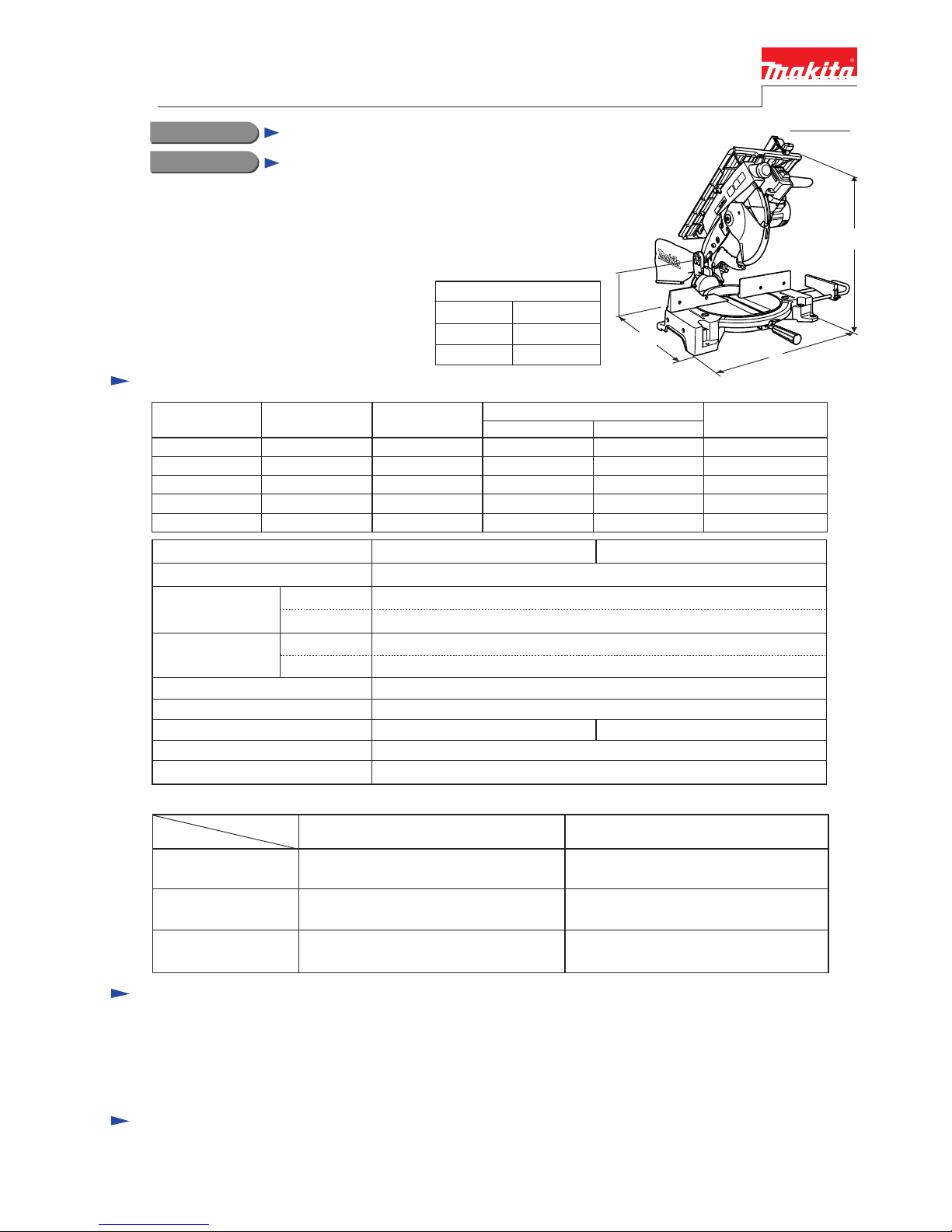
Dimensions: mm (")
Width (W)
Height (H)
Length (L)
476 (18-3/4)
530 (20-7/8)
535 (21)
LH1040, LH1040F
Table Top Miter Saw 260mm (10-1/4")
Models LH1040 and LH1040F have been
developed as multi-purpose miter saws.
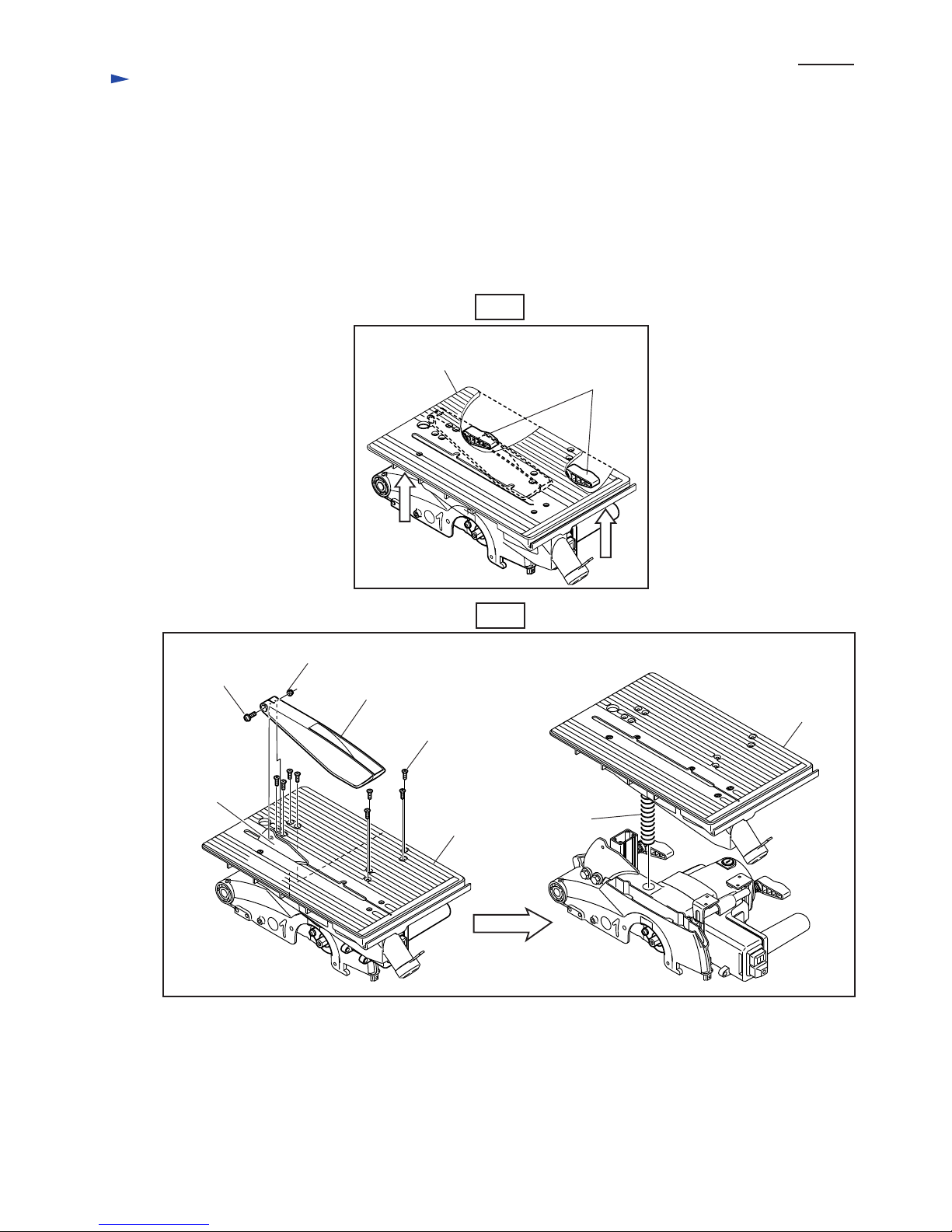
Installation of a table on Model LS1040
has enabled miter saw and table saw to be
packed in one tool for great versatility.
LH1040F features LED built-in job light
for accurate tracing of ink line in dark places.
Continuous Rating (W)
Voltage (V) Cycle (Hz) Input Output Max. Output(W)
120
110 15 1,650
1,650
2,30050 / 60
7.9 1,650 1,000 2,30050 / 60
7.5 1,650 1,000
1,000
1,000
2,30050 / 60
7.2 1,650 1,000 2,30050 / 60
15 2,30050 / 60
220
230
240
Current (A)
Model No.
No load speed: min-1 = rpm.
Cutting capacity as Miter Saw
LH1040
Double insulation
LH1040F
Diameter
Hole diameter
Protection against electric shock
Cord length: m (ft)
Net weight: kg (lbs)
LED job light
Miter angle
Bevel angle
Electric brake
Saw blade: mm (")
No Yes
Yes
4,800
255 - 260 (10 - 10-1/4 )
15.88 (5/8) 30.0 ( for European countries)
Table saw
Miter saw
Capacity: mm (")
(with 260 mm saw)
40 (1-9/16 )
See the table below.
2.5 ( 8.2 )
13.7 (30.2 )
90
°
45
° Left
69mm x 130mm (2-3/4" x 5-1/8")
93mm x 95mm (3-5/8" x 3-3/4")
35mm x 130mm (1-3/8" x 5-1/8")
53mm x 95mm (2-1/16" x 3-3/4")
35mm x 65mm (1-3/8" x 2-9/16")
49mm x 42mm (1-15/16" x 1-5/8")
35mm x 91mm (1-3/8" x 3-5/8")
49mm x 67mm (1-15/16" x 2-5/8")
69mm x 85mm (2-3/4" x 3-3/8")
93mm x 67mm (3-5/8" x 2-5/8")
69mm x 85mm (2-3/4" x 3-3/8")
93mm x 67mm (3-5/8" x 2-5/8")
45
° Left bevel
90
°
45
° Right
W
L
H
Standard equipment
Optional accessories
Note: The standard equipment listed above may differ from country to country.
TCT saw blade 260mm .......... 1 pc
Dust bag ................................. 1 pc
Holder set ............................... 1 pc
Sub plate ass'y ........................ 1 pc
Socket wrench 13 ....................... 1 pc
Ring 16 (adaptor for saw blades
with 25mm hole diameter) ......... 1 pc
Triangular rule ............................ 1 pc
Set plate ................................... 1 pc
Blade cover .............................. 1 pc
Push stick ................................. 1 pc
Guide rule rule ........................ 1 pc
Vertical vise
Horizontal vise
Holder set
Assorted TCT saw blades