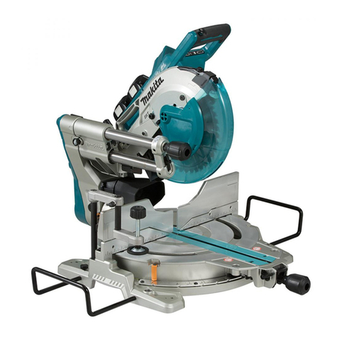
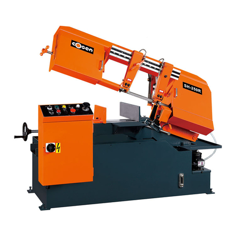
Makita M2300 User manual

M2300
EN Compound Miter Saw INSTRUCTION MANUAL 8
PL Ukośnica INSTRUKCJA OBSŁUGI 16
HU Kombinált gérvágó HASZNÁLATI KÉZIKÖNYV 25
SK Zložená píla na zrezávanie NÁVOD NA OBSLUHU 33
CS Pokosová pila NÁVOD K OBSLUZE 41
UK Комбінована торцювальна
пила
ІНСТРУКЦІЯ З
ЕКСПЛУАТАЦІЇ 49
RO Ferăstrău pentru tăieri oblice
combinate MANUAL DE INSTRUCŢIUNI 58
DE Kapp-und Gehrungssäge BETRIEBSANLEITUNG 66

1
Fig.1
1
Fig.2
1
2
3
Fig.3
1
Fig.4
1
Fig.5
1
Fig.6
1
Fig.7
1
Fig.8
2

1
Fig.9
2
1
3
130mm
Fig.10
1
2
Fig.11
1
Fig.12
1
Fig.13
1
2
Fig.14
1
Fig.15
1
2
Fig.16
3

1
Fig.17
1
2
Fig.18
12
3
4
Fig.19
1
23
4
5
6
Fig.20
1
Fig.21
1
Fig.22
1
Fig.23
12
Fig.24
4

1
2
4
3
Fig.25
Fig.26
1
Fig.27
Fig.28
123
Fig.29
(a) (b) (c) (d)
12
Fig.30
2
(a)
(b)
(a)
(b)
(b)
(a)
(b)
(a)
(a)
(b)
(c)
(d)
1
Fig.31
2
3
1
4
Fig.32
5

(a) (b) (c) (d)
12
Fig.33
1
2
3
4
5
Fig.34
≥ 10mm ≥ 460mm
11
25mm
100mm115mm 100mm115mm
Fig.35
1
2
3
Fig.36
1
Fig.37
Fig.38
11
Fig.39
1
Fig.40
6

1
Fig.41
1
2
3
Fig.42
1
Fig.43
1
2
Fig.44
Fig.45
1
2
Fig.46
7

8ENGLISH
ENGLISH (Original instructions)
SPECIFICATIONS
Model: M2300
Blade diameter 255 mm
Blade body thickness 1.6 mm - 2.4 mm
Hole diameter For all countries other than European countries 25.4 mm
For European countries 30 mm
No load speed 4,200 min-1
Dimensions (L x W x H) 610 mm x 485 mm x 515 mm
Net weight 14.7 kg
Safety class /II
Cutting capacities (H x W) with blade 255 mm in diameter
Bevel angle Miter angle
0° 45° (left and right)
0° 75 mm x 130 mm 75 mm x 90 mm
45° (left) 48 mm x 120 mm 48 mm x 90 mm
• Duetoourcontinuingprogramofresearchanddevelopment,thespecicationshereinaresubjecttochange
without notice.
• Specicationsmaydifferfromcountrytocountry.
• Weight according to EPTA-Procedure 01/2003
Symbols
The following show the symbols used for the equip-
ment. Be sure that you understand their meaning before
use.
Read instruction manual.
DOUBLE INSULATION
Toavoidinjuryfromyingdebris,keep
holding the saw head down, after making
cuts, until the blade has come to a com-
plete stop.
Donotplacehandorngersclosetothe
blade.
For your safety, remove the chips, small
pieces, etc. from the table top before
operation.
Always set SUB-FENCE to left position
when performing left bevel cuts. Failure to
dosomaycauseseriousinjurytooperator.
To loosen the bolt, turn it clockwise.
Only for EU countries
Do not dispose of electric equipment
together with household waste material! In
observance of the European Directive, on
Waste Electric and Electronic Equipment
and its implementation in accordance with
national law, electric equipment that have
reached the end of their life must be col-
lected separately and returned to an envi-
ronmentally compatible recycling facility.
Intended use
The tool is intended for accurate straight and miter
cutting in wood. With appropriate saw blades, aluminum
can also be sawed.
Power supply
The tool should be connected only to a power supply of
the same voltage as indicated on the nameplate, and
can only be operated on single-phase AC supply. They
are double-insulated and can, therefore, also be used
from sockets without earth wire.
Noise
The typical A-weighted noise level determined accord-
ing to EN61029:
Sound pressure level (LpA) : 92 dB(A)
Sound power level (LWA) : 105 dB (A)
Uncertainty (K) : 3 dB(A)
WARNING: Wear ear protection.

9ENGLISH
EC Declaration of Conformity
For European countries only
Makita declares that the following Machine(s):
Designation of Machine: Compound Miter Saw
Model No./ Type: M2300
Conforms to the following European Directives:
2006/42/EC
They are manufactured in accordance with the following
standard or standardized documents: EN61029
Thetechnicalleinaccordancewith2006/42/ECis
available from:
Makita, Jan-Baptist Vinkstraat 2, 3070, Belgium
1.1.2016
Yasushi Fukaya
Director
Makita, Jan-Baptist Vinkstraat 2, 3070, Belgium
General power tool safety warnings
WARNING: Read all safety warnings and
all instructions. Failure to follow the warnings and
instructionsmayresultinelectricshock,reand/or
seriousinjury.
Save all warnings and instruc-
tions for future reference.
The term "power tool" in the warnings refers to your
mains-operated (corded) power tool or battery-operated
(cordless) power tool.
MITER SAW SAFETY WARNINGS
1. Keep hands out of path of saw blade. Avoid
contact with any coasting blade. It can still
cause severe injury.
2. Check the saw blade carefully for cracks or
deformation before operation.
Replace damaged blades immediately.
3. Replace the kerf board when worn.
4. Use only saw blades specied by the manufac-
turer which conform to EN847-1.
5. Do not use saw blades manufactured from
high speed steel.
6. Wear eye protection.
7. Wear hearing protection to reduce the risk of
hearing loss.
8. Wear gloves for handling saw blade (saw
blades shall be carried in a holder wherever
practicable) and rough material.
9. Connect miter saws to a dust collecting device
when sawing.
10. Select saw blades in relation to the material to
be cut.
11. Do not use the saw to cut other than wood,
aluminum or similar materials.
12. Always secure all moving portions before car-
rying the tool. When lifting or carrying the tool,
do not use the guard as a carrying handle.
13. Do not operate saw without guards in place.
Check blade guard for proper closing before
each use. Do not operate saw if blade guard
does not move freely and close instantly.
Never clamp or tie the blade guard into the
open position.
14. Keep the oor area free of loose material e.g.
chips and cut-offs.
15. Use only saw blades that are marked with a
maximum speed equal to or higher than the no
load speed marked on the tool.
16. When the tool is tted with a laser or LED, do
not replace the laser or LED with a different
type. Ask an authorized service center for repair.
17. Never remove any cut-offs or other parts of the
workpiece from the cutting area whilst the tool
is running with an unguarded saw blade.
18. Do not perform any operation freehand. The
workpiecemustbesecuredrmlyagainstthe
turn base and guide fence with the vise during all
operations. Never use your hand to secure the
workpiece.
19. Ensure that the tool is stable before each cut.
20. Fix the tool to a work bench, if needed.
21. Support long workpieces with appropriate
additional supports.
22. Never cut so small workpiece which cannot be
securely held by the vise. Improperly held work-
piece may cause kickback and serious personal
injury.
23. Never reach around saw blade.
24. Turn off tool and wait for saw blade to stop
before moving workpiece or changing
settings.
25. Unplug tool before changing blade or
servicing.
26. Stopper pin which locks the cutter head down
is for carrying and storage purposes only and
not for any cutting operations.
27. Do not use the tool in the presence of amma-
ble liquids or gases. The electrical operation of
thetoolcouldcreateanexplosionandrewhen
exposedtoammableliquidsorgases.
28. Use only anges specied for this tool.
29. Be careful not to damage the arbor, anges
(especially the installing surface) or bolt.
Damage to these parts could result in blade
breakage.
30. Make sure that the turn base is properly
secured so it will not move during operation.
31. For your safety, remove the chips, small
pieces, etc. from the table top before
operation.
32. Avoid cutting nails. Inspect for and remove all
nails from the workpiece before operation.
33. Make sure the shaft lock is released before the
switch is turned on.
34. Be sure that the blade does not contact the
turn base in the lowest position.
35.
Hold the handle rmly. Be aware that the saw moves
up or down slightly during start-up and stopping.
36. Make sure the blade is not contacting the
workpiece before the switch is turned on.

10 ENGLISH
37. Before using the tool on an actual workpiece,
let it run for a while. Watch for vibration or
wobbling that could indicate poor installation
or a poorly balanced blade.
38. Wait until the blade attains full speed before
cutting.
39. Stop operation immediately if you notice any-
thing abnormal.
40. Do not attempt to lock the trigger in the on
position.
41. Be alert at all times, especially during repeti-
tive, monotonous operations. Do not be lulled
into a false sense of security. Blades are
extremely unforgiving.
42. Always use accessories recommended in this
manual. Use of improper accessories such as
abrasive wheels may cause an injury.
43. Take care when slotting.
44. Some dust created from operation contains
chemicals known to cause cancer, birth
defects or other reproductive harm. Some
examples of these chemicals are:
• Lead from lead-based-painted material
and, arsenic and chromium from chemi-
cally-treated lumber.
• Your risk from these exposures varies,
depending on how often you do this
type of work. To reduce your exposure
to these chemicals: work in a well venti-
lated area and work with approved safety
equipment, such as those dust masks
that are specially designed to lter out
microscopic particles.
45. To reduce the emitted noise, always be sure
that the blade is sharp and clean.
46. The operator is adequately trained in the use,
adjustment and operation of the machine.
SAVE THESE INSTRUCTIONS.
WARNING: DO NOT let comfort or familiarity
with product (gained from repeated use) replace
strict adherence to safety rules for the subject
product. MISUSE or failure to follow the safety
rules stated in this instruction manual may cause
serious personal injury.
INSTALLATION
When the tool is shipped, the handle is locked in the
lowered position by the stopper pin. Loosen the bolt
with a wrench provided with the tool and move the saw
head to the right angle. Remove the bolt and secure the
saw head with the knob.
►Fig.1: 1. Wrench
►Fig.2: 1. Knob
Installing auxiliary plate
Installing the auxiliary plate using the hole in the tool's
base and secure it by tightening the screw.
►Fig.3: 1. Auxiliary plate 2. Screw 3. Base
Bench mounting
When the tool is shipped, the handle is locked in the
lowered position by the stopper pin. Release the stop-
per pin by lowering the handle slightly and pulling the
stopper pin.
►Fig.4: 1. Stopper pin
This tool should be bolted with four bolts to a level and
stable surface using the bolt holes provided in the tool's
base.Thiswillhelppreventtippingandpossibleinjury.
►Fig.5: 1. Bolt
FUNCTIONAL
DESCRIPTION
CAUTION: Always be sure that the tool is
switched off and unplugged before adjusting or
checking function on the tool.
Blade guard
►Fig.6: 1. Blade guard
When lowering the handle, the blade guard rises auto-
matically. The guard is spring loaded so it returns to
its original position when the cut is completed and the
handle is raised. NEVER DEFEAT OR REMOVE THE
BLADE GUARD OR THE SPRING WHICH ATTACHES
TO THE GUARD.
In the interest of your personal safety, always maintain
the blade guard in good condition. Any irregular opera-
tion of the blade guard should be corrected immediately.
Check to assure spring loaded return action of guard.
NEVER USE THE TOOL IF THE BLADE GUARD OR
SPRING IS DAMAGED, FAULTY OR REMOVED.
DOING SO IS HIGHLY DANGEROUS AND CAN
CAUSE SERIOUS PERSONAL INJURY.
If the see-through blade guard becomes dirty, or saw-
dust adheres to it in such a way that the blade and/or
workpiece is no longer easily visible, unplug the saw
and clean the guard carefully with a damp cloth. Do not
use solvents or any petroleum-based cleaners on the
plastic guard.
If the blade guard is especially dirty and vision through
the guard is impaired, use the supplied wrench to
loosen the hex bolt holding the center cover. Loosen
the hex bolt by turning it counterclockwise and raise
the blade guard and center cover. With the blade guard
so positioned, cleaning can be more completely and
efcientlyaccomplished.Whencleaningiscomplete,
reverse procedure above and secure bolt. Do not
remove spring holding blade guard. If guard becomes
discolored through age or UV light exposure, contact
a Makita service center for a new guard. DO NOT
DEFEAT OR REMOVE GUARD.
►Fig.7: 1. Blade guard

11 ENGLISH
Kerf board
This tool is provided with the kerf board in the turn base
to minimize tearing on the exit side of a cut. If the kerf
groove has not yet been cut in the kerf board by the
factory, you should cut the groove before actually using
the tool to cut a workpiece. Switch on the tool and lower
the blade gently to cut a groove in the kerf board.
►Fig.8: 1. Kerf board
Maintaining maximum cutting
capacity
Thistoolisfactoryadjustedtoprovidethemaximum
cutting capacity for a 255 mm saw blade.
When installing a new blade, always check the lower
limitpositionofthebladeandifnecessary,adjustitas
follows:
First, unplug the tool. Lower the handle completely. Use
thewrenchtoturntheadjustingboltuntiltheperiphery
of the blade extends slightly below the top surface of
the turn base at the point where the front face of the
guide fence meets the top surface of the turn base.
►Fig.9: 1.Adjustingbolt
With the tool unplugged, rotate the blade by hand while
holding the handle all the way down to be sure that
the blade does not contact any part of the lower base.
Re-adjustslightly,ifnecessary.
►Fig.10: 1. Top surface of turn base 2. Periphery of
blade 3. Guide fence
CAUTION: After installing a new blade,
always be sure that the blade does not contact
any part of the lower base when the handle is
lowered completely. Always do this with the tool
unplugged.
Adjusting the miter angle
►Fig.11: 1. Lock lever 2. Grip
Loosen the grip by turning counterclockwise. Turn the
turn base while pressing down the lock lever. When you
have moved the grip to the position where the pointer
points to the desired angle on the miter scale, securely
tighten the grip clockwise.
CAUTION: When turning the turn base, be
sure to raise the handle fully.
CAUTION: After changing the miter angle,
always secure the turn base by tightening the grip
rmly.
Adjusting the bevel angle
►Fig.12: 1. Knob
Toadjustthebevelangle,loosentheknobattherearof
the tool counterclockwise.
►Fig.13: 1. Pointer
Push the handle to the left to tilt the saw blade until the
pointer points to the desired angle on the bevel scale.
Thentightentheknobclockwisermlytosecurethe
arm.
CAUTION: When tilting the saw blade, be sure
to raise the handle fully.
CAUTION: After changing the bevel angle,
always secure the arm by tightening the knob
clockwise.
Switch action
WARNING: Before plugging in the tool,
always check to see that the switch trigger actu-
ates properly and returns to the "OFF" position
when released. Operating a tool with a switch that
does not actuate properly can lead to loss of control
andseriouspersonalinjury.
WARNING: NEVER use tool without a fully
operative switch trigger. Any tool with an inoper-
ative switch is HIGHLY DANGEROUS and must be
repaired before further usage or serious personal
injurymayoccur.
For European countries
►Fig.14: 1. Lever 2. Switch trigger
To start the tool, push the lever to the right and then pull
the switch trigger. Release the switch trigger to stop.
For all countries other than European
countries
►Fig.15: 1. Switch trigger
To start the tool, simply pull the switch trigger. Release
the switch trigger to stop.
ASSEMBLY
CAUTION: Always be sure that the tool is
switched off and unplugged before carrying out
any work on the tool.
Installing or removing saw blade
CAUTION: Always be sure that the tool is
switched off and unplugged before installing or
removing the blade.
CAUTION: Use only the Makita wrench pro-
vided to install or remove the blade. Failure to
do so may result in overtightening or insufcient
tightening of the hex bolt. This could cause an
injury.
When removing or installing the blade, keep the handle
in the raised position.
To remove the blade, use the wrench to loosen the hex
bolt holding the center cover by turning it counterclock-
wise. Raise the blade guard and center cover.
►Fig.16: 1. Wrench 2. Center cover
►Fig.17: 1. Hex bolt

12 ENGLISH
Press the shaft lock to lock the spindle and use the
wrench to loosen the hex bolt clockwise. Then remove
thehexbolt,outerangeandblade.
►Fig.18: 1. Hex bolt 2. Wrench
To install the blade, mount it carefully onto the spindle,
making sure that the direction of the arrow on the sur-
face of the blade matches the direction of the arrow on
the blade case.
►Fig.19: 1. Blade case 2. Arrow 3. Arrow 4. Saw
blade
Installtheouterangeandhexbolt,andthenusethe
wrench to tighten the hex bolt (left-handed) securely
counterclockwise while pressing the shaft lock.
►Fig.20: 1. Spindle 2. Flange 3. Saw blade 4. Flange
5. Hex bolt 6. Ring
CAUTION: The ring 25.4 mm or 30 mm in
outer diameter is factory-installed onto the spin-
dle. Before mounting the blade onto the spindle,
always be sure that the correct ring for the arbor
hole of the blade you intend to use is installed
onto the spindle.
Return the blade guard and center cover to its original
position. Then tighten the hex bolt clockwise to secure
the center cover. Lower the handle to make sure that
the blade guard moves properly. Make sure shaft lock
has released spindle before making cut.
Sub-fence
For European countries only
CAUTION: When performing left bevel cuts,
ip the sub-fence outward. Otherwise, it may con-
tact the blade or a part of the tool, and may result in
seriousinjurytotheoperator.
►Fig.21: 1. Sub-fence
This tool is equipped with the sub-fence. Usually posi-
tion the sub-fence inside. However, when performing
leftbevelcuts,ipitoutward.
Dust bag
►Fig.22: 1. Dust bag
►Fig.23: 1. Fastener
The use of the dust bag makes cutting operations clean
anddustcollectioneasy.Toattachthedustbag,tit
onto the dust nozzle.
When the dust bag is about half full, remove the dust
bag from the tool and pull the fastener out. Empty
the dust bag of its contents, tapping it lightly so as to
remove particles adhering to the insides which might
hamper further collection.
NOTE: If you connect a Makita vacuum cleaner to
yoursaw,moreefcientandcleaneroperationscan
be performed.
Securing workpiece
WARNING: It is extremely important to always
secure the workpiece properly and tightly with
the vise. Failure to do so can cause the tool to be
damaged and/or the workpiece to be destroyed.
PERSONAL INJURY MAY ALSO RESULT. Also,
after a cutting operation, DO NOT raise the blade
until the blade has come to a complete stop.
CAUTION: When cutting long workpieces,
use supports that are as high as the top surface
level of the turn base. Do not rely solely on the
vertical vise and/or horizontal vise to secure the
workpiece. Thin material tends to sag. Support
workpiece over its entire length to avoid blade
pinch and possible KICKBACK.
►Fig.24: 1. Support 2. Turn base
Vertical vise
►Fig.25: 1. Vise knob 2. Screw 3. Vise arm 4. Vise
rod
The vertical vise can be installed in two positions on
either the left or right side of the guide fence. Insert the
vise rod into the hole in the guide fence and tighten the
screw to secure the vise rod.
Position the vise arm according to the thickness and
shape of the workpiece and secure the vise arm by
tightening the screw. Make sure that no part of the tool
contacts the vise when lowering the handle all the way.
If some part contacts the vise, re-position the vise.
Presstheworkpieceatagainsttheguidefenceandthe
turn base. Position the workpiece at the desired cutting
positionandsecureitrmlybytighteningtheviseknob.
CAUTION: The workpiece must be secured
rmly against the turn base and guide fence with
the vise during all operations.
OPERATION
►Fig.26
CAUTION: Before use, be sure to release the
handle from the lowered position by pulling the
stopper pin.
CAUTION: Make sure the blade is not con-
tacting the workpiece, etc. before the switch is
turned on.
CAUTION: Do not apply excessive pressure
on the handle when cutting. Too much force may
result in overload of the motor and/or decreased cut-
tingefciency.Pressdownhandlewithonlyasmuch
force as necessary for smooth cutting and without
signicantdecreaseinbladespeed.
CAUTION: Gently press down the handle
to perform the cut. If the handle is pressed down
with force or if lateral force is applied, the blade may
vibrate and leave a mark (saw mark) in the workpiece
and the precision of the cut may be impaired.

13 ENGLISH
Press cutting
►Fig.27: 1. Vertical vise
Secure the workpiece with the vise. Switch on the tool
without the blade making any contact and wait until the
blade attains full speed before lowering. Then gently
lower the handle to the fully lowered position to cut the
workpiece. When the cut is completed, switch off the
tool and WAIT UNTIL THE BLADE HAS COME TO A
COMPLETE STOP before returning the blade to its fully
elevated position.
Miter cutting
Refertothepreviouslycovered"Adjustingthemiter
angle".
Bevel cut
►Fig.28
Loosen the knob and tilt the saw blade to set the bevel
angle(Refertothepreviouslycovered"Adjustingthe
bevelangle").Besuretoretightentheknobrmlyto
secure the selected bevel angle safely. Secure the
workpiece with a vise. Switch on the tool without the
blade making any contact and wait until the blade
attains full speed. Then gently lower the handle to the
fully lowered position while applying pressure in parallel
with the blade. When the cut is completed, switch off the
tool and WAIT UNTIL THE BLADE HAS COME TO A
COMPLETE STOP before returning the blade to its fully
elevated position.
CAUTION: Always be sure that the blade will
move down to bevel direction during a bevel cut.
Keep hands out of path of saw blade.
CAUTION: During a bevel cut, it may create
a condition whereby the piece cut off will come
to rest against the side of the blade. If the blade is
raised while the blade is still rotating, this piece may
be caught by the blade, causing fragments to be scat-
tered which is dangerous. The blade should be raised
ONLY after the blade has come to a complete stop.
CAUTION: When pressing the handle down,
apply pressure parallel to the blade. If the pressure
is not parallel to the blade during a cut, the angle of
the blade might be shifted and the precision of the cut
will be impaired.
CAUTION: (Only for tools with sub-fence)
Always set the sub-fence outside when perform-
ing left bevel cuts.
Compound cutting
Compound cutting is the process in which a bevel
angle is made at the same time in which a miter angle
is being cut on a workpiece. Compound cutting can be
performed at the angle shown in the table.
Bevel angle Miter angle
45° Left and Right 0° - 45°
When performing compound cutting, refer to “Press
cutting”, “Miter cutting” and “Bevel cut” explanations.
Cutting crown and cove moldings
Crown and cove moldings can be cut on a compound
mitersawwiththemoldingslaidatontheturnbase.
There are two common types of crown moldings and
one type of cove moldings; 52/38° wall angle crown
molding, 45° wall angle crown molding and 45° wall
angle cove molding.
►Fig.29: 1. 52/38° type crown molding 2. 45° type
crown molding 3. 45° type cove molding
Therearecrownandcovemoldingjointswhichare
madetot"Inside"90°corners((a)and(b)inthegure)
and"Outside"90°corners((c)and(d)inthegure.)
►Fig.30: 1. Inside corner 2. Outside corner
►Fig.31: 1. Inside corner 2. Outside corner
Measuring
Measurethewallwidth,andadjustthewidthofthe
workpiece according to it. Always make sure that width
of the workpiece's wall contact edge is the same as wall
length.
►Fig.32: 1. Workpiece 2. Wall width 3. Width of the
workpiece 4. Wall contact edge
Always use several pieces for test cuts to check the
saw angles.
When cutting crown and cove moldings, set the bevel
angle and miter angle as indicated in the table (A) and
position the moldings on the top surface of the saw
base as indicated in the table (B).
In the case of left bevel cut
►Fig.33: 1. Inside corner 2. Outside corner
Table (A)
–Molding
position
in the
gure
Bevel angle Miter angle
52/38°
type
45° type 52/38°
type
45° type
For
inside
corner
(a) Left
33.9°
Left 30° Right
31.6°
Right
35.3°
(b) Left
31.6°
Left
35.3°
For
outside
corner
(c)
(d) Right
31.6°
Right
35.3°
Table (B)
–Molding
position in
the gure
Molding
edge against
guide fence
Finished
piece
For inside
corner
(a) Ceiling
contact edge
should be
against guide
fence.
Finished
piece will be
on the Left
side of blade.
(b) Wall contact
edge should
be against
guide fence.
For outside
corner
(c) Finished
piece will be
on the Right
side of blade.(d) Ceiling
contact edge
should be
against guide
fence.

14 ENGLISH
Example:
In the case of cutting 52/38° type crown molding for
position(a)intheabovegure:
• Tilt and secure bevel angle setting to 33.9° LEFT.
• Adjustandsecuremiteranglesettingto31.6°
RIGHT.
• Lay crown molding with its broad back (hidden)
surface down on the turn base with its CEILING
CONTACT EDGE against the guide fence on the
saw.
• Thenishedpiecetobeusedwillalwaysbeon
the LEFT side of the blade after the cut has been
made.
Cutting aluminum extrusion
►Fig.34: 1. Vise 2. Spacer block 3. Guide fence
4. Aluminum extrusion 5. Spacer block
When securing aluminum extrusions, use spacer blocks
orpiecesofscrapasshownintheguretoprevent
deformation of the aluminum. Use a cutting lubricant
when cutting the aluminum extrusion to prevent build-up
of the aluminum material on the blade.
CAUTION: Never attempt to cut thick or round
aluminum extrusions. Thick aluminum extrusions
may come loose during operation and round alumi-
numextrusionscannotbesecuredrmlywiththis
tool.
Wood facing
WARNING: Use screws to attach the wood
facing to the guide fence. The screws should be
installed so that the screw heads are below the
surface of the wood facing so that they will not
interfere with the positioning of the material being
cut. Misalignment of the material being cut can case
unexpected movement during the cutting operation
which may result in a loss of control and serious
personalinjury.
CAUTION: Use the straight wood of even
thickness as the wood facing.
Use of wood facing helps to assure splinter-free cuts
in workpieces. Attach a wood facing to the guide fence
using the holes in the guide fence.
Seethegureconcerningthedimensionsforasug-
gested wood facing.
►Fig.35: 1. Holes
NOTICE: When the wood facing is attached, do
not turn the turn base with the handle lowered.
The blade and/or the wood facing will be damaged.
NOTE: The maximum cutting width will be smaller by
the width of wood facing.
Cutting repetitive lengths
When cutting several pieces of stock to the same
length, ranging from 240 mm to 380 mm, use the set
plate (optional accessory). Install the set plate on the
holder(optionalaccessory)asshowninthegure.
►Fig.36: 1. Set plate 2. Holder 3. Screw
Align the cutting line on your workpiece with either the
left or right side of the groove in the kerf board, and
whileholdingtheworkpiece,movethesetplateush
against the end of the workpiece. Then secure the set
plate with the screw.
When the set plate is not used, loosen the screw and
turn the set plate out of the way.
NOTE: Use of the holder-rod assembly (optional
accessory) allows cutting repetitive lengths up to
2,200 mm approximately.
Carrying tool
►Fig.37: 1. Stopper pin
Make sure that the tool is unplugged. Secure the blade
at 0° bevel angle and the turn base at left miter angle
fully. Lower the handle fully and lock it in the lowered
position by pushing in the stopper pin.
Carrythetoolbycarryinggripasshowninthegure.If
you remove the holders, dust bag, etc., you can carry
the tool more easily.
►Fig.38
CAUTION: Always secure all moving portions
before carrying the tool.
CAUTION: Stopper pin is for carrying and
storage purposes only and not for any cutting
operations.
MAINTENANCE
WARNING: Always be sure that the blade is
sharp and clean for the best and safest perfor-
mance. Attempting a cut with a dull and /or dirty blade
may cause kickback and result in a serious personal
injury.
CAUTION: Always be sure that the tool is
switched off and unplugged before attempting to
perform inspection or maintenance.
NOTICE: Never use gasoline, benzine, thinner,
alcohol or the like. Discoloration, deformation or
cracks may result.
Adjusting the cutting angle
Thistooliscarefullyadjustedandalignedatthefactory,
but rough handling may have affected the alignment. If
your tool is not aligned properly, perform the following:
Miter angle
►Fig.39: 1. Hex bolt
Loosen the grip which secures the turn base. Turn the
turn base so that the pointer points to 0° on the miter
scale. Tighten the grip and loosen the hex bolts secur-
ing the guide fence using the wrench. If the pointer
does not point to 0° on the miter scale, loosen the screw
which secures the pointer and move and secure the
pointer plate so that the pointer points to 0° on the miter
scale.

15 ENGLISH
Lower the handle fully and lock it in the lowered position
by pushing in the stopper pin. Square the side of the
blade with the face of the guide fence using a triangular
rule, try-square, etc. Then securely tighten the hex bolts
on the guide fence in the order from the right side.
►Fig.40: 1. Triangular rule
Bevel angle
0° bevel angle
►Fig.41: 1.0°bevelangleadjustingbolt
Lower the handle fully and lock it in the lowered position
by pushing in the stopper pin.
Loosen the knob at the rear of the tool.
Loosenthehexnutandturnthe0°bevelangleadjust-
ing bolt on the right side of the turn base two or three
revolutions clockwise to tilt the blade to the right.
Carefully square the side of the blade with the top sur-
face of the turn base using the triangular rule, try-square,
etc.byturningthe0°bevelangleadjustingboltcoun-
terclockwise. Then tighten the hex nut to secure the 0°
bevelangleadjustingboltandtightentheknobsecurely.
Make sure that the pointer on the arm points to 0° on the bevel
scale. If it does not point to 0° on the bevel scale, loosen the
screw which secures the pointer and move and secure the
pointer plate so that the pointer points to 0° on the bevel scale.
►Fig.42: 1. Triangular rule 2. Saw blade 3. Top sur-
face of turn base
►Fig.43: 1. Pointer
45° bevel angle
►Fig.44: 1.45°bevelangleadjustingbolt2. Pointer
Adjustthe45°bevelangleonlyafterperforming0°
bevelangleadjustment.
Toadjustleft45°bevelangle,loosentheknobandtilt
the blade to the left fully.
Make sure that the pointer on the arm points to 45° on
the bevel scale on the arm.
If the pointer does not point to 45°, turn the 45° bevel
angleadjustingboltontheleftsideofthearmuntilthe
pointer points to 45°.
Replacing carbon brushes
►Fig.45
Remove and check the carbon brushes regularly. Replace when
they wear down to 3 mm in length. Keep the carbon brushes
clean and free to slip in the holders. Both carbon brushes should
be replaced at the same time. Use only identical carbon brushes.
Use a screwdriver to remove the brush holder caps.
Take out the worn carbon brushes, insert the new ones
and secure the brush holder caps.
►Fig.46: 1. Brush holder cap 2. Screwdriver
After use
After use, wipe off chips and dust adhering to the tool
with a cloth or the like. Keep the blade guard clean
according to the directions in the previously covered
section titled "Blade guard". Lubricate the sliding por-
tions with machine oil to prevent rust.
To maintain product SAFETY and RELIABILITY,
repairs,anyothermaintenanceoradjustmentshould
be performed by Makita Authorized or Factory Service
Centers, always using Makita replacement parts.

16 POLSKI
POLSKI (Instrukcja oryginalna)
DANE TECHNICZNE
Model: M2300
Średnicatarczy 255 mm
Grubośćtarczytnącej 1,6–2,4 mm
Średnicaotworu Krajepozaeuropejskie 25,4 mm
Krajeeuropejskie 30 mm
Prędkośćbezobciążenia 4 200 min-1
Wymiary(dług.xszer.xwys.) 610 mm x 485 mm x 515 mm
Ciężarnetto 14,7 kg
Klasabezpieczeństwa /II
Maks. zakres cięcia (wys. x szer.) w przypadku tarczy o średnicy 255 mm
Kąt cięcia w pionie Kąt cięcia w poziomie
0° 45° (w lewo i w prawo)
0° 75 mm x 130 mm 75 mm x 90 mm
45° (w lewo) 48 mm x 120 mm 48 mm x 90 mm
• Wzwiązkuzestaleprowadzonymprzeznasząrmęprogramembadawczo-rozwojowymniniejszedanemogą
uleczmianombezwcześniejszegopowiadomienia.
• Danetechnicznemogąróżnićsięwzależnościodkraju.
• CiężarpodanyzgodniezprocedurąEPTA01/2003.
Symbole
Poniżejpokazanosymbolezastosowanenaurządze-
niu.Przedrozpoczęciemużytkowanianależyzapoznać
sięzichznaczeniem.
Przeczytaćinstrukcjęobsługi.
PODWÓJNA IZOLACJA
Abyuniknąćobrażeńpowodowanych
odpryskami,nienależypodnosićgłowicy
tnącejpozakończeniucięcia,ażdoczasu
całkowitegozatrzymaniasiętarczy.
Dłonieipalcenależytrzymaćzdalaod
tarczy.
Dlawłasnegobezpieczeństwaprzedprzy-
stąpieniemdopracyusunąćwióry,drobne
kawałkimateriałuitp.zpowierzchnistołu.
Podczascięciapodkątemwpioniewlewą
stronęPROWADNICAPOMOCNICZA
powinnabyćustawionawlewympoło-
żeniu.Niestosowaniesiędotejzasady
możespowodowaćpoważneobrażenia
operatora.
Abypoluzowaćśrubę,należyobracaćją
w prawo.
DotyczytylkopaństwUE
Niewyrzucaćurządzeńelektrycznychwraz
z odpadami z gospodarstwa domowego!
Zgodniezdyrektywąeuropejskąwsprawie
zużytegosprzętuelektrycznegoielektro-
nicznegoorazdostosowaniemjejdoprawa
krajowego,zużyteurządzeniaelektryczne
należyskładowaćosobnoiprzekazywać
dozakładurecyklingudziałającegozgod-
niezprzepisamidotyczącymiochrony
środowiska.
Przeznaczenie
Narzędzietojestprzeznaczonedowykonywaniaprecy-
zyjnychcięćprostychiukośnychwdrewnie.
Zasilanie
Narzędziewolnopodłączaćtylkodoźródełzasilaniao
napięciuzgodnymznapięciempodanymnatabliczce
znamionowej.Możnajezasilaćwyłączniejednofazo-
wymprądemprzemiennym.Narzędziemapodwójną
izolację,dlategoteżmożnajezasilaćzgniazdaelek-
trycznego bez uziemienia.
Hałas
TypowyrównoważnypoziomdźwiękuAokreślonyw
oparciuonormęEN61029:
Poziomciśnieniaakustycznego(LpA): 92 dB(A)
Poziommocyakustycznej(LWA): 105 dB (A)
Niepewność(K):3dB(A)
OSTRZEŻENIE: Nosić ochronniki słuchu.

17 POLSKI
Deklaracja zgodności WE
Dotyczy tylko krajów europejskich
FirmaMakitaoświadcza,żeponiższeurządzenie(-a):
Oznaczeniemaszyny:Ukośnica
Model nr/typ: M2300
Jestzgodnezwymogamiokreślonymiwnastępujących
dyrektywacheuropejskich:2006/42/EC
Jest/sąprodukowanezgodnieznastępującyminor-
mamilubdokumentaminormalizacyjnymi:EN61029
Dokumentacjatechnicznazgodnawwymaganiami
dyrektywy2006/42/ECjestdostępnaw:
Makita, Jan-Baptist Vinkstraat 2, 3070, Belgia
1.1.2016
Yasushi Fukaya
Dyrektor
Makita, Jan-Baptist Vinkstraat 2, 3070, Belgia
Ogólne zasady bezpiecznej
eksploatacji elektronarzędzi
OSTRZEŻENIE: Przeczytać wszystkie ostrze-
żenia bezpieczeństwa i wszystkie instrukcje.
Niezastosowaniesiędowspomnianychostrzeżeńi
instrukcjimożedoprowadzićdoporażeniaprądem
elektrycznym,pożarui/lubpoważnychobrażeńciała.
Wszystkie ostrzeżenia i instruk-
cje należy zachować do wykorzy-
stania w przyszłości.
Pojęcie„elektronarzędzie",występującewwymienio-
nychtuostrzeżeniach,odnosisiędoelektronarzędzia
zasilanegozsiecielektrycznej(zprzewodemzasilają-
cym)lubdoelektronarzędziaakumulatorowego(bez
przewoduzasilającego).
OSTRZEŻENIA DOTYCZĄCE
BEZPIECZEŃSTWA DLA UKOŚNICY
1.
Trzymać ręce z dala od drogi, po której porusza się tar-
cza tnąca. Nie dotykać obracającej się z rozpędu tarczy.
Grozi to w dalszym ciągu poważnymi obrażeniami ciała.
2. Przed przystąpieniem do pracy dokładnie
sprawdzić tarczę tnącą pod kątem pęknięć lub
odkształceń.
Niezwłocznie wymieniać uszkodzone tarcze.
3. Wymieniać płytę nacięcia po zauważeniu na
niej śladów zużycia.
4.
Należy stosować wyłącznie tarcze tnące zalecane
przez producenta, zgodne z normą EN847-1.
5. Nie używać tarcz tnących wykonanych ze stali
szybkotnącej.
6. Należy stosować środki ochrony wzroku.
7. Nosić ochronniki słuchu, aby zmniejszyć
ryzyko utraty słuchu.
8. Podczas przenoszenia tarcz tnących oraz
ostrych materiałów należy nosić rękawice
(tarcze tnące należy umieszczać w uchwycie
zawsze, gdy jest to możliwe).
9. Podczas cięcia podłączać piłę do urządzenia
zbierającego pył.
10. Dobierać odpowiednie tarcze tnące do obra-
bianego materiału.
11. Nie używać pilarki do cięcia materiałów innych
niż drewno, aluminium lub do nich podobnych.
12. Przed przenoszeniem narzędzia należy zablo-
kować wszystkie ruchome elementy. Podczas
podnoszenia lub przenoszenia narzędzia nie
używać jego osłony jako uchwytu.
13. Nie uruchamiać piły bez założonych osłon.
Każdorazowo przed użyciem sprawdzić,
czy osłona prawidłowo się zamyka. Nie uru-
chamiać piły, jeśli osłona nie przesuwa się
swobodnie lub zamyka się z opóźnieniem.
Nie wolno w żadnym wypadku przywiązywać
osłony tarczy ani w inny sposób unierucha-
miać jej w pozycji otwartej.
14. Dbać, aby na podłodze nie leżały luźne mate-
riały i odpady, takie jak wióry czy ścinki.
15. Stosować wyłącznie tarcze tnące z ozna-
czeniem prędkości maksymalnej równej lub
wyższej niż wartość prędkości bez obciążenia
oznaczonej na narzędziu.
16. W przypadku gdy narzędzie jest wyposażone
w laser lub diodę LED, nie stosować podczas
ich wymiany innego typu lasera ani diody LED.
Zgłosićsiędoautoryzowanegocentrumserwiso-
wego w celu naprawy.
17. Nigdy nie usuwać żadnych ścinków ani innych
części elementu obrabianego z obszaru cięcia,
gdy narzędzie pracuje z nieosłoniętą tarczą
tnącą.
18. Nie wykonywać żadnych operacji, trzymając
obrabiany element w ręce. Obrabiany element
podczaswszystkichoperacjimusibyćdobrze
zamocowanywpodstawieobrotowejiprowadnicy
zapomocązacisku.Nigdynietrzymaćobrabia-
negoelementuręką.
19. Upewnić się, że narzędzie jest stabilne przed
wykonaniem każdego cięcia.
20. W razie konieczności przymocować narzędzie
do stołu warsztatowego.
21. Podeprzeć dłuższe elementy obrabiane przy
użyciu odpowiednich podpór.
22.
Nigdy nie ciąć małych elementów, których nie
można prawidłowo zamocować w zacisku.
Nieprawidłowozamocowanyelementmożezostać
odrzuconyispowodowaćpoważneobrażeniaciała.
23. Nie zbliżać rąk do tarczy tnącej.
24. Przed usunięciem obrabianego elementu lub
zmianą ustawień wyłączyć narzędzie i pocze-
kać, aż tarcza tnąca zatrzyma się.
25. Przed przystąpieniem do wymiany tarczy
lub czynności serwisowych należy odłączyć
narzędzie od zasilania.
26. Kołek oporowy blokujący głowicę tnącą w
położeniu opuszczonym ma zastosowanie
wyłącznie przy przenoszeniu lub przechowy-
waniu urządzenia, nigdy podczas cięcia.
27. Nie używać narzędzia w pobliżu łatwopalnych
płynów lub gazów.Pracaukładuelektrycznego
narzędziawobecnościłatwopalnychpłynówlub
gazówmożespowodowaćwybuchipożar.

18 POLSKI
28. Używać wyłącznie kołnierzy przeznaczonych
do tego urządzenia.
29. Uważać, aby nie uszkodzić wałka, kołnierzy
(szczególnie powierzchni mocujących) ani
śruby. Uszkodzenie tych części może być
przyczyną pęknięcia tarczy.
30. Upewnić się, że podstawa obrotowa jest
dobrze przymocowana i nie będzie się przesu-
wać podczas pracy.
31. Dla własnego bezpieczeństwa przed przy-
stąpieniem do pracy usunąć wióry, drobne
kawałki materiału itp. z powierzchni stołu.
32. Należy unikać cięcia gwoździ. Przed przystą-
pieniem do pracy sprawdzić obrabiany ele-
ment i usunąć z niego wszystkie gwoździe.
33. Przed włączeniem przełącznika sprawdzić, czy
blokada wałka została zwolniona.
34. Upewnić się, że tarcza w swoim najniższym
położeniu nie dotyka podstawy obrotowej.
35. Trzymać pewnie uchwyt urządzenia. Pamiętać,
że piła przesuwa się nieznacznie w górę lub w
dół na początku i na końcu cięcia.
36. Przed włączeniem przełącznika upewnić się, że
tarcza nie dotyka obrabianego elementu.
37. Przed rozpoczęciem obróbki danego elementu
pozwolić, aby urządzenie popracowało przez
chwilę bez obciążenia. Zwracać uwagę na
ewentualne drgania lub bicie osiowe, które
mogą wskazywać na nieprawidłowe zamoco-
wanie lub niedokładne wyważenie tarczy.
38. Rozpocząć cięcie, gdy tarcza osiągnie pełną
prędkość.
39. Natychmiast przerwać pracę po zauważeniu
jakiejkolwiek nieprawidłowości.
40. Nie próbować blokować spustu przełącznika w
pozycji włączenia.
41. Zawsze zachować czujność, szczególnie
podczas wykonywania powtarzających się,
monotonnych czynności. Nie dać się zwieść
pozornemu poczuciu bezpieczeństwa. Tarcze
są niezwykle niebezpieczne.
42. Zawsze używać akcesoriów zalecanych w
niniejszej instrukcji obsługi. Używanie nie-
właściwych akcesoriów, np. tarczy ściernych,
może być przyczyną obrażeń ciała.
43. Podczas wycinania rowków zachować
ostrożność.
44. Pył powstający w czasie pracy może zawierać
substancje chemiczne powodujące nowo-
twory, wady wrodzone oraz inne zaburzenia
płodności. Oto przykłady takich substancji:
• Ołów pochodzący materiałów pomalo-
wanych farbami ołowiowymi oraz arsen i
chrom pochodzący z drewna poddanego
obróbce chemicznej.
• Stopień narażenia na te substancje zależy
od tego, jak często wykonywane są tego
typu prace. Aby zmniejszyć zagrożenie na
powyższe substancje chemiczne: należy
pracować w miejscach dobrze wentylo-
wanych i używać sprawdzonych zabez-
pieczeń, takich jak maski przeznaczone
do odltrowywania mikroskopijnych
cząstek.
45. Aby obniżyć poziom powstającego podczas
pracy hałasu, należy zawsze stosować ostre i
czyste tarcze.
46. Operator powinien przejść prawidłowe szko-
lenie w zakresie używania, regulacji i obsługi
urządzenia.
ZACHOWAĆ NINIEJSZE
INSTRUKCJE.
OSTRZEŻENIE: NIE WOLNO pozwolić,
aby wygoda lub rutyna (nabyta w wyniku wielo-
krotnego używania urządzenia) zastąpiły ścisłe
przestrzeganie zasad bezpieczeństwa obsługi.
NIEWŁAŚCIWE UŻYTKOWANIE narzędzia lub
niestosowanie się do zasad bezpieczeństwa
podanych w niniejszej instrukcji obsługi może
prowadzić do poważnych obrażeń ciała.
INSTALACJA
Wprzypadkunowegonarzędziauchwytjestzabloko-
wanywdolnympołożeniuzapomocąkołkaoporowego.
Kluczemdostarczonymztymnarzędziempoluzować
śrubęiustawićgłowicępodkątemprostym.Wykręcić
śrubęizamocowaćgłowicępokrętłem.
►Rys.1: 1. Klucz
►Rys.2: 1.Pokrętło
Zakładanie płytki pomocniczej
Zamontowaćpłytkępomocniczą,przykręcającjąśrubą
dootworuwpodstawienarzędzia.
►Rys.3: 1.Płytkapomocnicza2.Śruba3. Podstawa
Mocowanie do stołu roboczego
Wprzypadkunowegonarzędziauchwytjestzabloko-
wanywdolnympołożeniuzapomocąkołkaoporowego.
Abyzwolnićkołekoporowy,opuścićlekkouchwyti
pociągnąćzakołekoporowy.
►Rys.4: 1.Kołekoporowy
Narzędzienależyprzykręcićczteremaśrubamido
poziomejistabilnejpowierzchni,wykorzystującotwory
wjegopodstawie.Wtensposóbmożnauniknąćprze-
wróceniasięnarzędziaiewentualnychobrażeńciała.
►Rys.5: 1.Śruba

19 POLSKI
OPIS DZIAŁANIA
PRZESTROGA: Przed rozpoczęciem regulacji
lub sprawdzeniem działania narzędzia należy
upewnić się, że jest ono wyłączone i nie podłą-
czone do sieci.
Osłona tarczy
►Rys.6: 1.Osłonatarczy
Podczasopuszczaniauchwytuosłonatarczypod-
nosisięautomatycznie.Osłonajestwyposażonaw
sprężynę,dlategowracadopierwotnegopołożenia
pozakończeniucięciaipodniesieniuuchwytu.NIE
WOLNOBLOKOWAĆANIZDEJMOWAĆOSŁONY
TARCZYISPRĘŻYNYMOCUJĄCEJOSŁONĘ.
Zewzględówbezpieczeństwoosłonatarczymusibyć
zawszewdobrymstanie.Jakiekolwieknieprawidłowo-
ściwjejdziałaniunależynatychmiastusunąć.Upewnić
się,czysprężynowymechanizmpowrotnyosłonydziała
prawidłowo.NIEWOLNOUŻYTKOWAĆNARZĘDZIA,
JEŚLIOSŁONATARCZYLUBSPRĘŻYNASĄ
USZKODZONE, WADLIWE LUB WYMONTOWANE.
UŻYWANIENARZĘDZIAWTAKIMSTANIEJEST
BARDZONIEBEZPIECZNEIMOŻEBYĆPRZYCZYNĄ
POWAŻNYCHOBRAŻEŃCIAŁA.
Jeśliprzezroczystaosłonatarczyzabrudzisięalbo
pokryjepyłemwtakimstopniu,żetarczai/lubobrabiany
elementniesądobrzewidoczne,należyodłączyć
pilarkęistaranniewyczyścićosłonęwilgotnąście-
reczką.Doczyszczeniaplastikowejosłonyniewolno
stosowaćrozpuszczalnikówaniśrodkówczyszczących
na bazie benzyny.
Jeżeliosłonatarczyjestwyjątkowobrudnaiwidocz-
nośćprzezosłonępogorszysię,poluzowaćśrubę
sześciokątnąmocującąpokrywęśrodkowązapomocą
dostarczonegoklucza.Odkręcićśrubęsześciokątną
wlewoipodnieśćosłonętarczyipokrywęśrodkową.
Takiepołożenieosłonytarczypozwalanajejdokład-
niejszeisprawniejszewyczyszczenie.Pozakończeniu
czyszczenianależywykonaćpodanepowyżejczynno-
ściwodwrotnejkolejnościidokręcićśrubę.Niewolno
wymontowywaćsprężynyprzytrzymującejosłonętar-
czy.Jeśliosłonasięprzebarwiwrazzupływemczasu
lubpodwpływempromieniowaniaUV,należyskontak-
towaćsięzpunktemserwisowymnarzędziMakitaw
celuzamówienianowejosłony.NIEBLOKOWAĆANI
NIEZDEJMOWAĆOSŁONY.
►Rys.7: 1.Osłonatarczy
Płyta nacięcia
Narzędziejestwyposażonewpłytęnacięciazamo-
cowanąwpodstawieobrotowej,któraminimalizuje
wystrzępieniemateriałupostroniewyjściowejpodczas
cięcia.Jeśliroweknacięciawpłycienacięcianiezostał
fabrycznienacięty,należygowykonaćprzedprzystą-
pieniemdoużywaniaurządzenia.Włączyćnarzędzie
iopuścićdelikatnietarczę,abynaciąćrowekwpłycie
nacięcia.
►Rys.8: 1.Płytanacięcia
Zachowanie maksymalnego zakresu
cięcia
Narzędziejestfabryczniewyregulowanewtakisposób,
abyzapewnićmaksymalnyzakrescięciadlatarcz
tnącychośrednicy255mm.
Zakładającnowątarczę,zawszenależysprawdzićjej
dolnepołożeniegraniczneiwraziepotrzebywyregulo-
waćwnastępującysposób:
Najpierwnależyodłączyćnarzędzieodzasilania.
Opuścićcałkowicieuchwyt.Obracaćkluczemśrubę
regulacyjną,ażkrawędźtarczyznajdziesięnieznacznie
poniżejgórnejpowierzchnipodstawyobrotowejwpunk-
cie,wktórympłaszczyznaczołowaprowadnicystyka
sięzgórnąpowierzchniąpodstawyobrotowej.
►Rys.9: 1.Śrubaregulacyjna
Przynarzędziuodłączonymodzasilaniaobrócićręką
tarczę,przytrzymującuchwytwskrajnymdolnympoło-
żeniu,abyupewnićsię,żetarczaniedotykażadnej
częścidolnejpodstawy.Wraziepotrzebynależyskory-
gowaćnieznacznieustawienie.
►Rys.10: 1.Górnapowierzchniapodstawyobrotowej
2.Krawędźtarczy3. Prowadnica
PRZESTROGA: Po zamontowaniu nowej tarczy
należy sprawdzić, czy tarcza nie styka się z żadną
częścią dolnej podstawy, gdy uchwyt jest całkowi-
cie opuszczony. Czynność tę należy wykonywać
zawsze przy odłączonym zasilaniu narzędzia.
Regulacja kąta cięcia w poziomie
►Rys.11: 1.Dźwigniablokady2.Rączka
Poluzowaćrączkę,obracającjąwlewo.Obrócićpod-
stawęobrotową,naciskającjednocześniewdółdźwi-
gnięblokady.Poprzesunięciurączkidopołożenia,w
którymwskaźnikpokazujenapodziałcekątacięciaw
poziomieżądanykąt,mocnodokręćrączkęwprawo.
PRZESTROGA: Obracają podstawę obrotową
należy całkowicie podnieść uchwyt.
PRZESTROGA: Po zmianie kąta cięcia w pozio-
mie należy zawsze unieruchomić podstawę obro-
tową, dokręcając mocno rączkę.
Regulacja kąta cięcia w pionie
►Rys.12: 1.Pokrętło
Abyzmienićustawieniekątacięciawpionie,należy
poluzowaćpokrętłoztyłunarzędzia,obracającjąw
lewo.
►Rys.13: 1.Wskaźnik
Popchnąćuchwytwlewo,abyprzechylićtarczętnącą,
ażwskaźnikwskażeżądanykątnapodziałcekąta
cięciawpionie.Następniedokręcićmocnopokrętłow
prawąstronę,abyunieruchomićramię.
PRZESTROGA: Podczas przechylania tarczy
tnącej należy całkowicie podnieść uchwyt.
PRZESTROGA: Po zmianie ustawienia kąta cię-
cia w pionie należy zawsze unieruchomić ramię,
dokręcając dźwignię w prawo.

20 POLSKI
Działanie przełącznika
OSTRZEŻENIE: Przed podłączeniem narzę-
dzia do zasilania należy zawsze sprawdzić, czy
spust przełącznika działa prawidłowo oraz czy
wraca do położenia wyłączenia po zwolnieniu.
Obsługanarzędzia,wprzypadkunieprawidłowego
działaniaprzełącznika,możeprowadzićdoutraty
kontrolinadnarzędziemorazpoważnychobrażeń
ciała.
OSTRZEŻENIE: NIE WOLNO użytkować
narzędzia, w którym spust przełącznika działa
nieprawidłowo.Narzędziezniesprawnymprzełącz-
nikiemstanowiPOWAŻNEZAGROŻENIEinależy
jenaprawićprzedponownymużyciem;nieprzestrze-
ganietegozaleceniagrozipoważnymiobrażeniami
ciała.
Kraje europejskie
►Rys.14: 1.Dźwignia2.Spustprzełącznika
Abyuruchomićnarzędzie,popchnąćdźwignięwprawo,
anastępniepociągnąćzaspustprzełącznika.Wcelu
wyłączeniawystarczyzwolnićspustprzełącznika.
Kraje pozaeuropejskie
►Rys.15: 1.Spustprzełącznika
Wceluuruchomienianarzędziawystarczypociągnąć
spustprzełącznika.Wceluwyłączeniawystarczyzwol-
nićspustprzełącznika.
MONTAŻ
PRZESTROGA: Przed wykonywaniem jakich-
kolwiek prac przy narzędziu należy upewnić się,
że jest ono wyłączone i odłączone od zasilania.
Zakładanie i zdejmowanie tarczy
tnącej
PRZESTROGA: Przed przystąpieniem do
wymiany tarczy zawsze upewnić się, czy narzę-
dzie jest wyłączone i odłączone od zasilania.
PRZESTROGA: Do zakładania i zdejmowania
tarczy należy używać wyłącznie dostarczonego
klucza rmy Makita. Niezastosowanie się do tego
zalecenia może spowodować nadmierne lub
niedostateczne dokręcenie śruby sześciokątnej.
Może to spowodować obrażenia ciała.
Podczaszakładanialubzdejmowaniatarczyuchwyt
powinienbyćpodniesiony.
Abyzdjąćtarczę,odkręcićkluczemśrubęsześciokątną
wlewąstronę,przytrzymującąpokrywęśrodkową.
Podnieśćosłonętarczyipokrywęśrodkową.
►Rys.16: 1. Klucz 2.Pokrywaśrodkowa
►Rys.17: 1.Śrubasześciokątna
Nacisnąćblokadęwałka,abyzablokowaćwrzeciono,
anastępnieodkręcićwprawośrubęsześciokątnąza
pomocąklucza.Następniewyjąćśrubęsześciokątnąi
ściągnąćkołnierzzewnętrznyoraztarczę.
►Rys.18: 1.Śrubasześciokątna2. Klucz
Abyzamontowaćtarczę,należyjąostrożnieumieścić
nawrzecionie,upewniającsię,czykierunekstrzałkina
powierzchnitarczyjestzgodnyzkierunkiemstrzałkina
jejobudowie.
►Rys.19: 1. Obudowa tarczy 2.Strzałka3.Strzałka
4.Tarczatnąca
Założyćkołnierzzewnętrznyiśrubęsześciokątną,a
następniedokręćmocnośrubęsześciokątną(zlewym
gwintem)wlewąstronęzapomocąklucza,wciskając
jednocześnieblokadęwałka.
►Rys.20: 1. Wrzeciono 2.Kołnierz3. Tarcza
tnąca4.Kołnierz5.Śrubasześciokątna
6.Pierścień
PRZESTROGA: Na wrzecionie jest fabrycznie
zamontowany pierścień o średnicy zewnętrznej
25,4 mm lub 30 mm. Przed zamocowaniem tarczy
na wrzecionie należy zawsze upewnić się, czy na
wrzecionie został założony właściwy pierścień
dopasowany do otworu tarczy, która będzie
używana.
Ustawićosłonętarczyipokrywęśrodkowąwpier-
wotnympołożeniu.Następniedokręćwprawośrubę
sześciokątnąmocującąpokrywęśrodkową.Opuścić
uchwyt,abyupewnićsię,czyosłonatarczyporuszasię
prawidłowo.Przedrozpoczęciemcięcianależyspraw-
dzić,czyblokadawałkajestzwolniona.
Prowadnica pomocnicza
Dotyczy tylko krajów europejskich
PRZESTROGA: Przed przystąpieniem do
wykonywania cięć pod kątem w pionie z lewej
strony należy odwrócić prowadnicę pomocniczą
na zewnątrz. Wprzeciwnymrazieprowadnicamoże
stykaćsięztarcząlubczęściąnarzędzia,grożąc
operatorowipoważnymiobrażeniamiciała.
►Rys.21: 1. Prowadnica pomocnicza
Narzędziejestwyposażonewprowadnicępomocniczą.
Standardowoprowadnicapomocniczajestustawiona
dowewnątrz.Jednakżewprzypadkuwykonywaniacięć
pokkątemwpioniezlewejstronyprowadnicęnależy
odwrócićnazewnątrz.
Worek na pył
►Rys.22: 1.Woreknapył
►Rys.23: 1. Zamek
Stosowanieworkanapyłpozwalanaczystecięciei
ułatwiazbieraniepyłu.Woreknapyłzakładasięna
króciecodpylania.
Gdyworekzapełnisięwprzybliżeniuwpołowie,należy
zdjąćgoznarzędziairozpiąćzamek.Opróżnićworek
ilekkogowytrzepać,abyusunąćpyłprzylegającydo
powierzchniwewnętrznych,gdyżmożetopogarszać
skutecznośćodbieraniapyłu.
Other manuals for M2300
5
Table of contents
Languages:
Other Makita Saw manuals

Makita
Makita 2704N User manual

Makita
Makita DLS211 User manual

Makita
Makita RS001G User manual

Makita
Makita LS1019L User manual

Makita
Makita JR3050T User manual

Makita
Makita LS1221 User manual

Makita
Makita Maktec MT241 Manual

Makita
Makita MLT100 User manual

Makita
Makita LSSOODWA User manual

Makita
Makita LS1216 User manual

Makita
Makita DPB180 User manual

Makita
Makita LF1000 User manual

Makita
Makita DPB181 User manual

Makita
Makita 5603R User manual

Makita
Makita 5903R User manual

Makita
Makita 5037NB User manual

Makita
Makita LS004G User manual

Makita
Makita JR3050T User manual

Makita
Makita GSH05 User manual

Makita
Makita EA3500S User guide