Makita LS1040F User manual

GB
Compound Miter Saw Instruction Manual
F
Scie à coupe d’onglet mixte Manuel d’instructions
D
Gehrungs- und Kappsäge Betriebsanleitung
I
Sega a quartabuono composta Istruzioni per l’uso
NL
Gecombineerde verstekzaag Gebruiksaanwijzing
E
Sierra de inglete mixta Manual de instrucciones
P
Serra de esquadria composta Manual de instruções
DK
Afkorter-geringssav Brugsanvisning
GR
Σύνθετος πριονωτς δίσκος
Οδηγίες χρήσεως
LS1040F

2
8
9
10
11
12 13
14
15
12
34
56
78
2
1
36
45
7

3
21
19
22
20
32
910
11 12
13 14
15 16
17
16
18
23
24
25 26
27
28
29
30 31
33 34

4
54 55
56
57
17 18
19 20
21 22
23 24
48
47 50 49
51
52
53
40
39
41
45
46
42
44
43
35
37 38
36

5
67
68
65
66
76
75
74
73
77
25 26
27 28
29 30
31
58
60 59 64
61
62
63
69 70
72
71

6
32
33 34
35 36
37 38
78 78
110 111
86
84
85
87
88
89
90
83
82
81
79
80
90 mm
(3–9/16”)
25 mm
(1”)
90 mm
(3–9/16”)
107 mm
(4–7/32”)
107 mm
(4–7/32”) 90 mm
(3–9/16”)

7
91
93
92
94 97
95
96
99
98
101
100
104
102 103 102
106
105
108
109
39 40
41
42
43 44

8
Symbols
The followings show the symbols used for the equipment. Be sure that you understand their meaning before use.
Symboles
Nous donnons ci-dessous les symboles utilisés pour l’outil. Assurez-vous que vous en avez bien compris la significa-
tion avant d’utiliser l’outil.
Symbole
Die folgenden Symbole werden für die Maschine verwendet. Machen Sie sich vor der Benutzung unbedingt mit ihrer
Bedeutung vertraut.
Symboli
Per questo utensile vengono usati i simboli seguenti. Bisogna capire il loro significato prima di usare l’utensile.
Symbolen
Voor dit gereedschap worden de volgende symbolen gebruikt. Zorg ervoor dat u de betekenis van deze symbolen
begrijpt alvorens het gereedschap te gebruiken.
Símbolos
A continuación se muestran los símbolos utilizados con esta herramienta. Asegúrese de que entiende su significado
antes de usarla.
Símbolos
O seguinte mostra os símbolos utilizados para a ferramenta. Certifique-se de que compreende o seu significado antes
da utilização.
Symboler
Nedenstående symboler er anvendt i forbindelse med denne maskine. Vær sikker på, at De har forstået symbolernes
betydning, før maskinen anvendes.
Σύμβολα
Τα ακλουθα δείχνουν τα σύμβολα που χρησιμοποιούνται για το μηχάνημα. Βεβαιωθείτε τι καταλαβαίνετε
τη σημασία τους πριν απ τη χρήση.
• Read instruction manual. • Lea el manual de instrucciones.
• Lire le mode d’emploi. • Leia o manual de instruções.
• Bitte Bedienungsanleitung lesen. • Læs brugsanvisningen.
• Leggete il manuale di istruzioni. • Διαβάστε τις οδηγίες χρήσης.
• Lees de gebruiksaanwijzing.
• DOUBLE INSULATION • DOBLE AISLAMIENTO
• DOUBLE ISOLATION • DUPLO ISOLAMENTO
• DOPPELT SCHUTZISOLIERT • DOBBELT ISOLERET
• DOPPIO ISOLAMENTO •ΔΙΠΛΗΜΟΝΩΣΗ
• DUBBELE ISOLATIE
• To avoid injury from flying debris, keep holding the saw head down, after making cuts, until the blade
has come to a complete stop.
• Pour éviter les blessures causées par les objets projetés, maintenez la tête de la scie en position
basse une fois la coupe terminée, jusqu’à ce que la lame soit complètement arrêtée.
• Um Verletzungen durch herausgeschleuderte Teile zu vermeiden, halten Sie den Sägekopf nach
Ausführung von Schnitten abgesenkt, bis das Sägeblatt völlig zum Stillstand gekommen ist.
• Per evitare lesioni dalle schegge volanti, dopo aver eseguito il taglio tenere abbassata la testa sega
finché la lama non si è arrestata completamente.
• Om verwonding door weggeslingerd zaagafval te voorkomen, dient u na het voltooien van een snede
de zaagkop omlaag te houden totdat het zaagblad volledig tot stilstand is gekomen.
• Para evitar sufrir heridas a causa de restos que salen despedidos, siga sujetando la cabeza de la
sierra hacia abajo, al terminar los cortes, hasta que el disco se haya parado completamente.
• Para evitar danos causados por aparas que saltem, mantenha a cabeça da serra para baixo, depois
de terminar os cortes, até que a lâmina esteja completamente parada.
• For at undgå at komme til skade på grund af flyvende affald, skal man holde savhovedet nede efter
skæring, indtil savklingen står helt stille.
• Για να αποφύγετε τραυματισμ απ ιπτάμενα τεμαχίδια, κρατάτε το πρινι με το κεφάλι προς
τα κάτω, αφού κάνετε κοπές, μέχρι η λάμα να σταματήσει τελείως.

9
• Do not place hand or fingers close to the blade.
• Ne pas placer les mains ou les doigts près de la lame.
• Halten Sie Hände oder Finger vom Sägeblatt fern.
• Non avvicinare le mani o le dita alla lama.
• Kom met uw handen of vingers niet te dicht bij het zaagblad.
• No ponga la mano ni los dedos cerca del disco.
• Não coloque a sua mão ou dedos perto da lâmina.
• Hold hænder og fingre på god afstand af klingen.
• Μη βάζετε το χέρι ή τα δάκτυλα κοντά στην λάμα.
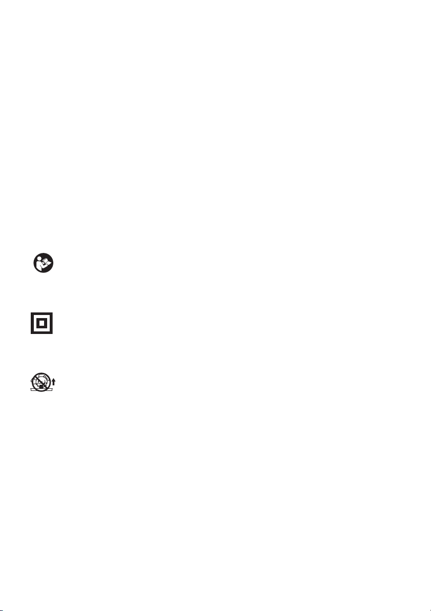
• For your safety, remove chips, small pieces, etc. from the table top before operation.
• Pour votre sécurité, retirez les copeaux et autres petites pièces présentes sur la table avant de com-
mencer le travail.
• Zur Sicherheit sollte die Tischplatte vor dem Betrieb von Spänen, Kleinteilen usw. gesäubert werden.
• Per la propria sicurezza, togliere i trucioli, frammenti, ecc., dalla superficie superiore del piano di
taglio prima di procedere.
• Verwijder voor uw eigen veiligheid zaagafval, stukjes hout e.d. van de werktafel alvorens te gaan
zagen.
• Por su propia seguridad, retire las virutas, trozos pequeños, etc., de encima de la mesa de trabajo
antes de iniciar la tarea.
• Para sua segurança, retire aparas, peças pequenas, etc., de cima da bancada antes da operação.
• Af sikkerhedsårsager skal spåner, små stykker etc. fjernes fra bordtoppen inden anvendelsen.
• Για την ασφάλειά σας, αφαιρέστε τα αποκοπίδια, μικρά κομμάτια, κλπ. απ το τραπέζι πριν
απ την λειτουργία.
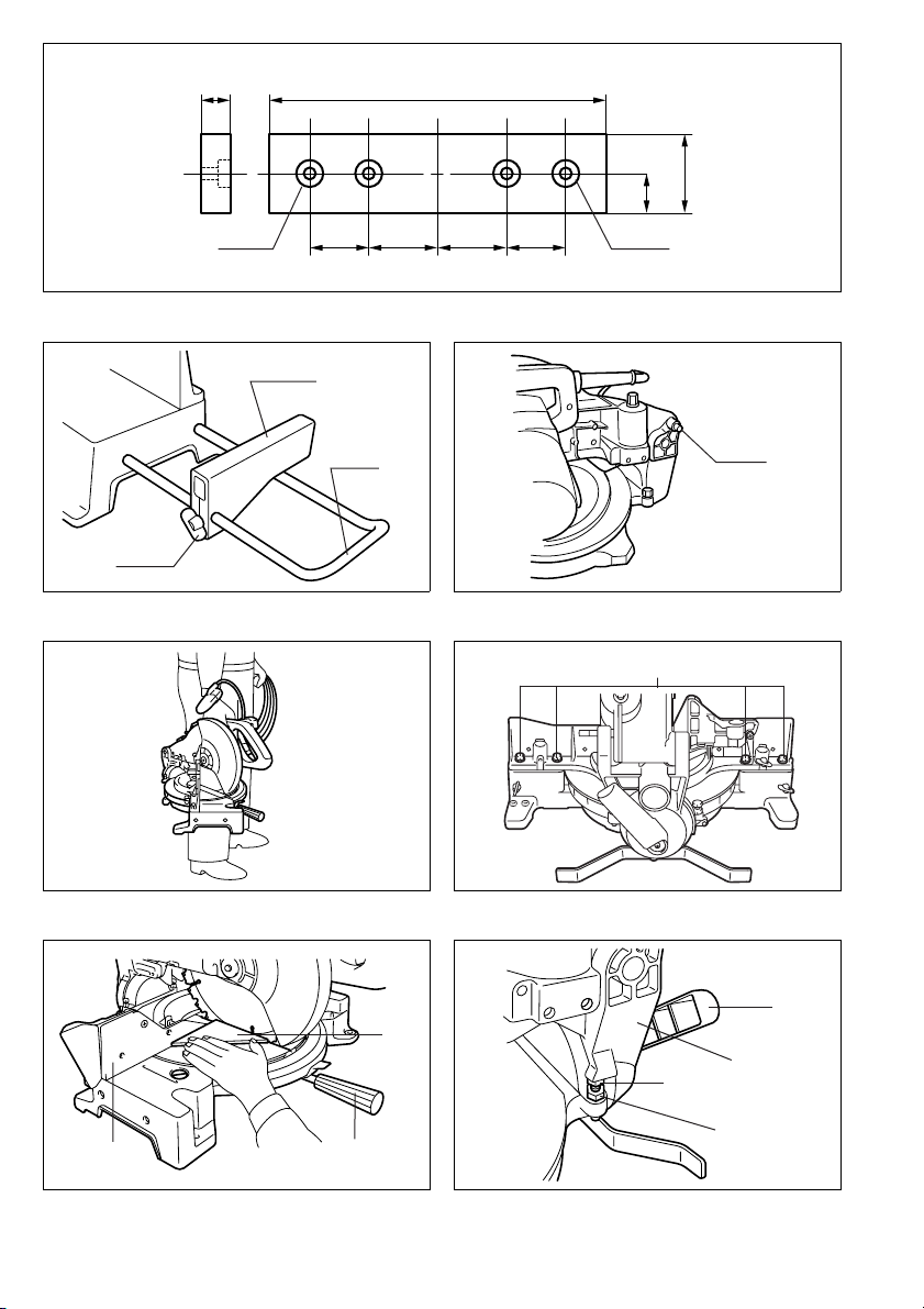
• Always set SUB-FENCE to left position when performing left bevel cuts. Failure to do so may cause
serious injury to operator.
• Lorsque vous effectuez des coupes en biseau sur la gauche, placez toujours la BUTÉE PARE-
ÉCLATS ROTATIVE à gauche. Sinon, il y a risque de blessure grave.
• Stellen Sie den ZUSATZANSCHLAG bei der Durchführung von Neigungsschnitten immer auf die
linke Position. Anderenfalls kann die Bedienungsperson ernsthaft verletzt werden.
• Posizionare sempre la guida pezzo secondaria a sinistra prima di eseguire i tagli a unghia. In caso
contrario, c’è pericolo di lesioni serie all’operatore.
• Zet de HULPGELEIDER altijd in de linkse positie wanneer u linkse schuine sneden wilt zagen. Als u
dit niet doet, kan de gebruiker ernstige verwonding oplopen.
• Ponga siempre la GUÍA AUXILIAR en la posición izquierda cuando realice cortes en bisel izquierdo.
De lo contrario, podrá sufrir graves heridas.
• Coloque sempre a GUIA AUXILIAR no lado esquerdo quando executa cortes de bisel à esquerda. Se
não o fizer pode ferir o operador.
• Anbing altid hjælpeanslaget (SUB-FENCE) i venstre position, når der laves skråsnit. Forsømmelse af
dette kan bevirke, at operatøren kommer alvorligt til skade.
• Πάντοτε ρυθμίζετε το SUB-FENCE (ΥΠΟ-ΦΡΑΚΤΗ) στην αριστερή θέση ταν εκτελείτε
αριστερές λοξές κοπές. Αμέλεια να το κάνετε μπορεί να προκαλέσει σοβαρ τραυματισμ
στον χρήστη.
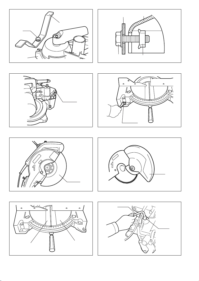
• To loosen the bolt, turn it clockwise.
• Pour desserrer le boulon, tournez-le vers la droite.
• Drehen Sie die Schraube zum Lösen im Uhrzeigersinn.
• Per allentare il bullone, girarlo in senso orario.
• Draai de bout rechtsom los.
• Para aflojar el perno, gírelo hacia la derecha.
• Para desapertar o perno, rode-o no sentido dos ponteiros do relógio.
• Bolten løsnes ved at den drejes i retningen med uret.
• Για να ξεσφίξετε τον κοχλία, περιστρέψτε δεξιστροφα.

10
• Only for EU countries
Do not dispose of electric equipment together with household waste material!
In observance of European Directive 2002/96/EC on waste electrical and electronic equipment and
its implementation in accordance with national law, electric equipment that have reached the end of
their life must be collected separately and returned to an environmentally compatible recycling facility.
• Pour les pays européens uniquement
Ne pas jeter les équipements électriques dans les ordures ménagères !
Conformément à la directive européenne 2002/96/EG relative aux déchets d’équipements électriques
ou électroniques (DEEE), et à sa transposition dans la législation nationale, les équipements élec-
triques doivent être collectés à part et être soumis à un recyclage respectueux de l’environnement.
• Nur für EU-Länder
Werfen Sie Elektrogeräte nicht in den Hausmüll!
Gemäß Europäischer Richtlinie 2002/96/EG über Elektro- und Elektronik-Altgeräte und Umsetzung in
nationales Recht müssen verbrauchte Elektrogeräte getrennt gesammelt und einer umweltgerechten
Wiederverwertung zugeführt werden.
• Solo per Paesi UE
Non gettare le apparecchiature elettriche tra i rifiuti domestici.
Secondo la Direttiva Europea 2002/96/CE sui rifiuti di apparecchiature elettriche ed elettroniche e la
sua attuazione in conformità alle norme nazionali, le apparecchiature elettriche esauste devono
essere raccolte separatamente, al fine di essere riciclate in modo eco-compatibile.
• Alleen voor EU-landen
Geef elektrische apparaten niet met het huisvuil mee!
Volgens de Europese richtlijn 2002/96/EG inzake oude elektrische en elektronische apparaten en de
toepassing daarvan binnen de nationale wetgeving, dient gebruikt elektrische apparaten gescheiden
te worden ingezameld en te worden afgevoerd naar een recycle bedrijf dat voldoet aan de geldende
milieu-eisen.
• Sólo para países de la Unión Europea
¡No deseche los aparatos eléctricos junto con los residuos domésticos!
De conformidad con la Directiva Europea 2002/96/CE sobre residuos de aparatos eléctricos y elec-
trónicos y su aplicación de acuerdo con la legislación nacional, los aparatos eléctricos cuya vida útil
haya llegado a su fin se deberán recoger por separado y trasladar a una planta de reciclaje que cum-
pla con las exigencias ecológicas.
• Apenas para países da UE
Não deite ferramentas eléctricas no lixo doméstico!
De acordo com a directiva europeia 2002/96/CE sobre ferramentas eléctricas e electrónicas usadas
e a sua aplicação para as leis nacionais, as ferramentas eléctricas usadas deven ser recolhidas em
separado e encaminhadas a uma instalação de reciclagem dos materiais ecológicos.
• Kun for EU-lande
Elværktøj må ikke bortskaffes som almindeligt affald!
I henhold til det europæiske direktiv 2002/96/EF om bortskaffelse af elektriske og elektroniske
produkter og gældende national lovgivning skal brugt elværktøj indsamles separat og returneres til
miljøgodkendt genindvinding.
• Μνο για τις χώρες της ΕΕ
Μη πετάτε τα είδη ηλεκτρικού εξοπλισμού μαζί με τα οικιακά απορρίμματα.
Σε τήρηση της Eυρωπαϊκής Oδηγίας 2002/96/ΕΚ, περί απορριμμάτων ειδών ηλεκτρικού και
ηλεκτρονικού εξοπλισμού και την εφαρμογή της σύμφωνα με την εθνική νομοθεσία, τα είδη
ηλεκτρικού εξοπλισμού που έχουν φθάσει στο τέλος της ζωής τους πρέπει να συλλέγονται
ξεχωριστά και να επιστρέφονται σε μιά περιβαλλοντικά συμβατή εγκατάσταση ανακύκλωσης.

11
ENGLISH (Original instructions)
Explanation of general view
1 Auxiliary plate
2 Hex bolt
3Base
4 Auxiliary plate
5Base
6 Hex bolt
7Nut
8 Stopper pin
9Bolt
10 Blade guard
11 Blade guard
12 Kerf board
13 Turn base
14 Socket wrench
15 Adjusting bolt
16 Top surface of turn base
17 Periphery of blade
18 Guide fence
19 Pointer
20 Lock lever
21 Grip
22 Miter scale
23 Lever
24 Lever
25 Bevel scale
26 Pointer
27 Lock-off button
28 Switch trigger
29 Lever
30 Lock-off button
31 Switch trigger
32 Light switch
33 Light
34 Light switch
35 Center cover
36 Socket wrench
37 Hex bolt
38 Blade guard
39 Socket wrench
40 Shaft lock
41 Spindle
42 Flange
43 Saw blade
44 Flange
45 Hex bolt
46 Ring
47 Blade case
48 Arrow
49 Saw blade
50 Arrow
51 Dust nozzle
52 Dust bag
53 Fastener
54 Support
55 Turn base
56 Sub-fence
57 Sub-fence
58 Vise arm
59 Vise rod
60 Guide fence
61 Holder
62 Holder assembly
63 Screw
64 Vise knob
65 Vise knob
66 Projection
67 Vise shaft
68 Base
69 Holder
70 Holder assembly
71 Holder assembly
72 Rod 12
73 Vise
74 Spacer block
75 Guide fence
76 Aluminum extrusion
77 Spacer block
78 Hole
79 Set plate
80 Holder
81 Screw
82 Stopper pin
83 Hex bolt
84 Triangular rule
85 Grip
86 Guide fence
87 Arm
88 Lever
89 0° adjusting bolt
90 Hex nut
91 Triangular rule
92 Saw blade
93 Top surface of turn base
94 Arm
95 Bevel scale
96 Pointer
97 Turn base
98 Lever
99 Arm
100 Pointer
101 45° bevel angle adjusting bolt
102 Pull out
103 Push
104 Lamp box
105 Screws
106 Fluorescent tube
107 Limit mark
108 Brush holder cap
109 Screwdriver
110 Over 10 mm (3/8”)
111 Over 460 mm (18–1/8”)
SPECIFICATIONS
Model LS1040F
Blade diameter ....................................................................................................................................255 mm – 260 mm
Hole diameter
For all countries other than European countries ...........................................................................25.4 mm and 25 mm
For European countries ......................................................................................................................................30 mm
Max. Miter angle............................................................................................................................... Left 45°, Right 52°
Max. Bevel angle ...............................................................................................................................................Left 45°
Max. cutting capacities (H x W) with blade 260mm in diameter
No load speed (min–1) ............................................................................................................................................ 4,600
Dimensions (L x W x H) .....................................................................................................530 mm x 476 mm x 532 mm
Net weight ............................................................................................................................................................ 12.6 kg
Safety class ............................................................................................................................................................. /II
Bevel angle Miter angle
0° 45° (left and right)
0° 93 mm x 95 mm
69 mm x 135 mm 93 mm x 67 mm
69 mm x 95 mm
45° (left) 53 mm x 95 mm
35 mm x 135 mm 49 mm x 67 mm
35 mm x 94 mm

12
• Due to our continuing program of research and devel-
opment, the specifications herein are subject to change
without notice.
• Specifications may differ from country to country.
• Weight according to EPTA-Procedure 01/2003
Intended use
The tool is intended for accurate straight and miter cut-
ting in wood. With appropriate saw blades, aluminum can
also be sawed.
Power supply
The tool should be connected only to a power supply of
the same voltage as indicated on the nameplate, and can
only be operated on single-phase AC supply. They are
double-insulated in accordance with European Standard
and can, therefore, also be used from sockets without
earth wire.
GEA010-1
General Power Tool Safety Warnings
WARNING Read all safety warnings and all
instructions. Failure to follow the warnings and
instructions may result in electric shock, fire and/or
serious injury.
Save all warnings and instructions for future refer-
ence.
ENB034-3
ADDITIONAL SAFETY RULES FOR TOOL
1. Wear eye protection.
2. Keep hands out of path of saw blade. Avoid con-
tact with any coasting blade. It can still cause
severe injury.
3. Do not operate saw without guards in place.
Check blade guard for proper closing before
each use. Do not operate saw if blade guard
does not move freely and close instantly. Never
clamp or tie the blade guard into the open posi-
tion.
4. Do not perform any operation freehand. The
workpiece must be secured firmly against the turn
base and guide fence with the vise during all opera-
tions. Never use your hand to secure the workpiece.
5. Never reach around saw blade.
6. Turn off tool and wait for saw blade to stop
before moving workpiece or changing settings.
7. Unplug tool before changing blade or servicing.
8. Always secure all moving portions before carry-
ing the tool.
9. Stopper pin which locks the cutter head down is
for carrying and storage purposes only and not
for any cutting operations.
10. Do not use the tool in the presence of flammable liq-
uids or gases.
11. Check the blade carefully for cracks or damage
before operation.
Replace cracked or damaged blade immediately.
12. Use only flanges specified for this tool.
13. Be careful not to damage the arbor, flanges (espe-
cially the installing surface) or bolt. Damage to these
parts could result in blade breakage.
14. Make sure that the turn base is properly secured so
it will not move during operation.
15. For your safety, remove the chips, small pieces, etc.
from the table top before operation.
16. Avoid cutting nails. Inspect for and remove all nails
from the workpiece before operation.
17. Make sure the shaft lock is released before the
switch is turned on.
18. Be sure that the blade does not contact the turn
base in the lowest position.
19. Hold the handle firmly. Be aware that the saw moves
up or down slightly during start-up and stopping.
20. Make sure the blade is not contacting the workpiece
before the switch is turned on.
21. Before using the tool on an actual workpiece, let it
run for a while. Watch for vibration or wobbling that
could indicate poor installation or a poorly balanced
blade.
22. Wait until the blade attains full speed before cutting.
23. Stop operation immediately if you notice anything
abnormal.
24. Do not attempt to lock the trigger in the on position.
25. Be alert at all times, especially during repetitive,
monotonous operations. Do not be lulled into a false
sense of security. Blades are extremely unforgiving.
26. Always use accessories recommended in this man-
ual. Use of improper accessories such as abrasive
wheels may cause an injury.
27. Do not use the saw to cut other than wood, alu-
minum or similar materials.
28. Connect miter saws to a dust collecting device
when sawing.
29. Select saw blades in relation to the material to
be cut.
30. Take care when slotting.
31. Replace the kerf board when worn.
32. Do not use saw blades manufactured from high
speed steel.
33. Some dust created from operation contains
chemicals known to cause cancer, birth defects
or other reproductive harm. Some examples of
these chemicals are:
• lead from lead-based-painted material and,
• arsenic and chromium from chemically-treated
lumber.
Your risk from these exposures varies, depend-
ing on how often you do this type of work. To
reduce your exposure to these chemicals: work
in a well ventilated area and work with approved
safety equipment, such as those dust masks
that are specially designed to filter out micro-
scopic particles.
34. To reduce the emitted noise, always be sure that
the blade is sharp and clean.
35. The operator is adequately trained in the use,
adjustment and operation of the machine.
36. Use correctly sharpened saw blades. Observe
the maximum speed marked on the saw blade.
37. Refrain from removing any cut-offs or other
parts of the workpiece from the cutting area
whilst the machine is running and the saw head
is not in the rest position.
SAVE THESE INSTRUCTIONS

13
INSTALLATION
Installing auxiliary plate (Fig. 1 & 2)
Install the auxiliary plate using the notch in the tool’s
base and secure it by tightening the hex bolt.
Bench mounting
When the tool is shipped, the handle is locked in the low-
ered position by the stopper pin. Release the stopper pin
by lowering the handle slightly and pulling the stopper
pin. (Fig. 3)
This tool should be bolted with two bolts to a level and
stable surface using the bolt holes provided in the tool’s
base. This will help prevent tipping and possible personal
injury. (Fig. 4)
FUNCTIONAL DESCRIPTION
CAUTION:
• Always be sure that the tool is switched off and
unplugged before adjusting or checking function on the
tool.
Blade guard (Fig. 5 & 6)
When lowering the handle, the blade guard rises auto-
matically. The guard is spring loaded so it returns to its
original position when the cut is completed and the han-
dle is raised. NEVER DEFEAT OR REMOVE THE
BLADE GUARD OR THE SPRING WHICH ATTACHES
TO THE GUARD.
In the interest of your personal safety, always maintain
the blade guard in good condition. Any irregular opera-
tion of the blade guard should be corrected immediately.
Check to assure spring loaded return action of guard.
NEVER USE THE TOOL IF THE BLADE GUARD OR
SPRING ARE DAMAGED, FAULTY OR REMOVED.
DOING SO IS HIGHLY DANGEROUS AND CAN CAUSE
SERIOUS PERSONAL INJURY.
If the see-through blade guard becomes dirty, or sawdust
adheres to it in such a way that the blade is no longer
easily visible, unplug the saw and clean the guard care-
fully with a damp cloth. Do not use solvents or any petro-
leum-based cleaners on the plastic guard.
If the blade guard is especially dirty and vision through
the guard is impaired, use the supplied socket wrench to
loosen the hex bolt holding the center cover. Loosen the
hex bolt by turning it counterclockwise and raise the
blade guard and center cover. With the blade guard so
positioned, cleaning can be more completely and effi-
ciently accomplished. When cleaning is complete,
reverse procedure above and secure bolt. Do not remove
spring holding blade guard. If guard becomes discolored
through age or UV light exposure, contact a Makita ser-
vice center for a new guard. DO NOT DEFEAT OR
REMOVE GUARD.
Kerf board (Fig. 7)
This tool is provided with the kerf board in the turn base
to minimize tearing on the exit side of a cut. If the kerf
groove has not yet been cut in the kerf board by the fac-
tory, you should cut the groove before actually using the
tool to cut a workpiece. Switch on the tool and lower the
blade gently to cut a groove in the kerf board.
Maintaining maximum cutting capacity (Fig. 8 & 9)
This tool is factory adjusted to provide the maximum cut-
ting capacity for a 260 mm saw blade.
When installing a new blade, always check the lower limit
position of the blade and if necessary, adjust it as follows:
First, unplug the tool. Lower the handle completely. Use
the socket wrench to turn the adjusting bolt until the
periphery of the blade extends slightly below the top sur-
face of the turn base at the point where the front face of
the guide fence meets the top surface of the turn base.
With the tool unplugged, rotate the blade by hand while
holding the handle all the way down to be sure that the
blade does not contact any part of the lower base. Re-
adjust slightly, if necessary.
CAUTION:
• After installing a new blade, always be sure that the
blade does not contact any part of the lower base when
the handle is lowered completely. Always do this with
the tool unplugged.
Adjusting the miter angle (Fig. 10)
Loosen the grip by turning counterclockwise. Turn the
turn base while pressing down the lock lever. When you
have moved the grip to the position where the pointer
points to the desired angle on the miter scale, securely
tighten the grip clockwise.
CAUTION:
• When turning the turn base, be sure to raise the handle
fully.
• After changing the miter angle, always secure the turn
base by tightening the grip firmly.
Adjusting the bevel angle (Fig. 11 & 12)
To adjust the bevel angle, loosen the lever at the rear of
the tool counterclockwise.
Push the handle to the left to tilt the saw blade until the
pointer points to the desired angle on the bevel scale.
Then tighten the lever clockwise firmly to secure the arm.
CAUTION:
• When tilting the saw blade, be sure to raise the handle
fully.
• After changing the bevel angle, always secure the arm
by tightening the lever clockwise.
Switch action
CAUTION:
• Before plugging in the tool, always check to see that
the switch trigger actuates properly and returns to the
“OFF” position when released.
• When not using the tool, remove the lock-off button and
store it in a secure place. This prevents unauthorized
operation.
• Do not pull the switch trigger hard without pressing in
the lock-off button. This can cause switch breakage.
For European countries (Fig. 13)
To prevent the switch trigger from being accidentally
pulled, a lock-off button is provided.
To start the tool, raise the lever, depress the lock-off but-
ton and pull the switch trigger. Release the switch trigger
to stop.

14
For all countries other than European countries
(Fig. 14)
To prevent the switch trigger from being accidentally
pulled, a lock-off button is provided.
To start the tool, depress the lock-off button and pull the
switch trigger. Release the switch trigger to stop.
WARNING:
• NEVER use tool without a fully operative switch trigger.
Any tool with an inoperative switch is HIGHLY DAN-
GEROUS and must be repaired before further usage.
• For your safety, this tool is equipped with a lock-off but-
ton which prevents the tool from unintended starting.
NEVER use the tool if it runs when you simply pull the
switch trigger without pressing the lock-off button.
Return tool to a Makita service center for proper repairs
BEFORE further usage.
• NEVER tape down or defeat purpose and function of
lock-off button.
Lighting up the lamps (Fig. 15 & 16)
CAUTION:
• This is not a rainproof light. Do not wash the light in
water or use it in a rain or a wet area. Such a conduct
can cause an electric shock and fume.
• Do not touch the lens of the light, as it is very hot while
it is lighted or shortly after it is turned off. This may
cause a burn to a human body.
• Do not apply impact to the light, which may cause dam-
age or shorted service time to it.
• Do not keep casting the beam of the light to your eyes.
This can cause your eyes to be hurt.
• Do not cover the light with clothes, carton, cardboard or
similar objects while it is lighted, which can cause a fire
or an ignition.
Push the upper position of the switch for turning on the
light and the lower position for off.
Move the light to shift an area of lighting.
NOTE:
• Use a dry cloth to wipe the dirt off the lens of lamp. Be
careful not to scratch the lens of light, or it may lower
the illumination.
ASSEMBLY
CAUTION:
• Always be sure that the tool is switched off and
unplugged before carrying out any work on the tool.
Installing or removing saw blade
CAUTION:
• Always be sure that the tool is switched off and
unplugged before installing or removing the blade.
• Use only the Makita socket wrench provided to install
or remove the blade. Failure to do so may result in
overtightening or insufficient tightening of the hex bolt.
This could cause a personal injury.
To remove the blade, use the socket wrench to loosen
the hex bolt holding the center cover by turning it coun-
terclockwise. Raise the blade guard and center cover.
(Fig. 17)
Press the shaft lock to lock the spindle and use the
socket wrench to loosen the hex bolt clockwise. Then
remove the hex bolt, outer flange and blade. (Fig. 18)
To install the blade, mount it carefully onto the spindle,
making sure that the direction of the arrow on the surface
of the blade matches the direction of the arrow on the
blade case. Install the outer flange and hex bolt, and then
use the socket wrench to tighten the hex bolt (left-
handed) securely counterclockwise while pressing the
shaft lock. (Fig. 19)
CAUTION:
For all countries other than European countries
• The silver ring 25.4 mm in outer diameter is factory-
installed onto the spindle. The black ring 25 mm in
outer diameter is included as standard equipment.
Before mounting the blade onto the spindle, always be
sure that the correct ring for the arbor hole of the blade
you intend to use is installed onto the spindle.
For European countries
• The ring 30 mm in outer diameter is factory-installed
onto the spindle.
Install the flange and hex bolt, and then use the socket
wrench to tighten the hex bolt securely counterclockwise
while pressing the shaft lock.
Return the blade guard and center cover to its original
position. Then tighten the hex bolt clockwise to secure
the center cover. Lower the handle to make sure that the
blade guard moves properly. Make sure shaft lock has
released spindle before making cut. (Fig. 20)
Dust bag (Fig. 21)
The use of the dust bag makes cutting operations clean
and dust collection easy. To attach the dust bag, fit it onto
the dust nozzle.
When the dust bag is about half full, remove the dust bag
from the tool and pull the fastener out. Empty the dust
bag of its contents, tapping it lightly so as to remove par-
ticles adhering to the insides which might hamper further
collection.
NOTE:
• If you connect a Makita vacuum cleaner to this tool,
more efficient and cleaner operations can be per-
formed.
Securing workpiece (Fig. 22)
WARNING:
• It is extremely important to always secure the work-
piece properly and tightly with the vise. Failure to do so
can cause the tool to be damaged and/or the work-
piece to be destroyed. PERSONAL INJURY MAY
ALSO RESULT. Also, after a cutting operation, DO
NOT raise the blade until the blade has come to a com-
plete stop.
CAUTION:
• When cutting long workpieces, use supports that are
as high as the top surface level of the turn base. Do not
rely solely on the vertical vise and/ or horizontal vise to
secure the workpiece.
Thin material tends to sag. Support workpiece over its
entire length to avoid blade pinch and possible KICK-
BACK.

15
Sub-fence (Fig. 23 & 24)
This tool is equipped with the sub-fence. It should be
positioned as shown in Fig. 23.
CAUTION:
• When performing left bevel cuts, flip the fence over to
the left position as shown in Fig. 24. Otherwise, it will
contact the blade or a part of the tool, causing possible
serious injury to the operator.
1. Vertical vise (Fig. 25)
The vertical vise can be installed in two positions on
either the left or right side of the guide fence or the holder
assembly (optional accessory). Insert the vise rod into
the hole in the guide fence or the holder assembly and
tighten the screw to secure the vise rod.
Position the vise arm according to the thickness and
shape of the workpiece and secure the vise arm by tight-
ening the screw. If the screw to secure the vise arm con-
tacts the guide fence, install the screw on the opposite
side of vise arm. Make sure that no part of the tool con-
tacts the vise when lowering the handle all the way. If
some part contacts the vise, re-position the vise.
Press the workpiece flat against the guide fence and the
turn base. Position the workpiece at the desired cutting
position and secure it firmly by tightening the vise knob.
CAUTION:
• The workpiece must be secured firmly against the turn
base and guide fence with the vise during all opera-
tions.
2. Horizontal vise (optional accessory) (Fig. 26)
The horizontal vise can be installed on either the left or
right side of the base. When performing 15° or greater
miter cuts, install the horizontal vise on the side opposite
the direction in which the turn table is to be turned. By
turning the vise knob counterclockwise, the screw is
released and the vise shaft can be moved rapidly in and
out. By turning the vise knob clockwise, the screw
remains secured. To grip the workpiece, turn the vise
knob gently clockwise until the projection reaches its top-
most position, then fasten securely. If the vise knob is
forced in or pulled out while being turned clockwise, the
projection may stop at an angle. In this case, turn the
vise knob back counterclockwise until the screw is
released, before turning again gently clockwise.
The maximum width of the workpiece which can be
secured by the horizontal vise is 130 mm.
CAUTION:
• Grip the workpiece only when the projection is at the
topmost position. Failure to do so may result in insuffi-
cient securing of the workpiece. This could cause the
workpiece to be thrown, cause damage to the blade or
cause the loss of control, which can result in PER-
SONAL INJURY.
3. Holders and holder assembly
(optional accessories) (Fig. 27)
The holders and the holder assembly can be installed on
either side as a convenient means of supporting work-
pieces horizontally. Install them as shown in Fig. 27.
Then tighten the screws firmly to secure the holders and
the holder assembly.
When cutting long workpieces, use the holder-rod
assembly (optional accessory). It consists of two holder
assemblies and two rods 12. (Fig. 28)
CAUTION:
• Always support long workpieces level with the top sur-
face of the turn base for accurate cuts and to prevent
dangerous loss of control of the tool.
OPERATION
CAUTION:
• Before use, be sure to release the handle from the low-
ered position by pulling the stopper pin.
• Make sure the blade is not contacting the workpiece,
etc. before the switch is turned on.
• Do not apply excessive pressure on the handle when
cutting. Too much force may result in overload of the
motor and/or decreased cutting efficiency. Push down
handle with only as much force as is necessary for
smooth cutting and without significant decrease in
blade speed.
• Gently press down the handle to perform the cut. If the
handle is pressed down with force or if lateral force is
applied, the blade will vibrate and leave a mark (saw
mark) in the workpiece and the precision of the cut will
be impaired.
1. Press cutting (Fig. 29)
Secure the workpiece with the vise. Switch on the tool
without the blade making any contact and wait until the
blade attains full speed before lowering. Then gently
lower the handle to the fully lowered position to cut the
workpiece. When the cut is completed, switch off the tool
and WAIT UNTIL THE BLADE HAS COME TO A COM-
PLETE STOP before returning the blade to its fully ele-
vated position.
2. Miter cutting
Refer to the previously covered “Adjusting the miter
angle”.
3. Bevel cut (Fig. 30)
Loosen the lever and tilt the saw blade to set the bevel
angle (Refer to the previously covered “Adjusting the
bevel angle”). Be sure to retighten the lever firmly to
secure the selected bevel angle safely. Secure the work-
piece with a vise. Switch on the tool without the blade
making any contact and wait until the blade attains full
speed. Then gently lower the handle to the fully lowered
position while applying pressure in parallel with the
blade. When the cut is completed, switch off the tool and
WAIT UNTIL THE BLADE HAS COME TO A COM-
PLETE STOP before returning the blade to its fully ele-
vated position.
CAUTION:
• Always be sure that the blade will move down to bevel
direction during a bevel cut. Keep hands out of path of
saw blade.
• During a bevel cut, it may create a condition whereby
the piece cut off will come to rest against the side of the
blade. If the blade is raised while the blade is still rotat-
ing, this piece may be caught by the blade, causing
fragments to be scattered which is dangerous. The
blade should be raised ONLY after the blade has come
to a complete stop.
• When pressing the handle down, apply pressure paral-
lel to the blade. If the pressure is not parallel to the
blade during a cut, the angle of the blade might be
shifted and the precision of the cut will be impaired.
• Always set the sub-fence to the left position when per-
forming left bevel cuts.

16
4. Compound cutting
Compound cutting is the process in which a bevel angle
is made at the same time in which a miter angle is being
cut on a workpiece. Compound cutting can be performed
at angle shown in the table.
When performing compound cutting, refer to “Press cut-
ting”, “Miter cutting” and “Bevel cut” explanations.
5. Cutting aluminum extrusion (Fig. 31)
When securing aluminum extrusions, use spacer blocks
or pieces of scrap as shown in Fig. 31 to prevent defor-
mation of the aluminum. Use a cutting lubricant when
cutting the aluminum extrusion to prevent buildup of the
aluminum material on the blade.
CAUTION:
• Never attempt to cut thick or round aluminum extru-
sions. Thick aluminum extrusions may come loose dur-
ing operation and round aluminum extrusions cannot
be secured firmly with this tool.
6. Wood facing (Fig. 32)
Use of wood facing helps to assure splinter-free cuts in
workpieces. Attach a wood facing to the guide fence
using the holes in the guide fence.
See Fig. 32 concerning the dimensions for a suggested
wood facing.
CAUTION:
• Use straight wood of even thickness as the wood fac-
ing.
• Use screws to attach the wood facing to the guide
fence. The screws should be installed so that the screw
heads are below the surface of the wood facing.
• When the wood facing is attached, do not turn the turn
base with the handle lowered. The blade and/or the
wood facing will be damaged.
7. Cutting repetitive lengths (Fig. 33)
When cutting several pieces of stock to the same length,
ranging from 240 mm to 400 mm, use of the set plate
(optional accessory) will facilitate more efficient opera-
tion. Install the set plate on the holder (optional acces-
sory) as shown in Fig. 33.
Align the cutting line on your workpiece with either the
left or right side of the groove in the kerf board, and while
holding the workpiece from moving, move the set plate
flush against the end of the workpiece. Then secure the
set plate with the screw. When the set plate is not used,
loosen the screw and turn the set plate out of the way.
NOTE:
• Use of the holder-rod assembly (optional accessory)
allows cutting repetitive lengths up to 2,200 mm (7.2 ft.)
approximately.
Carrying tool
Make sure that the tool is unplugged. Secure the blade at
0° bevel angle and the turn base at left miter angle fully.
Lower the handle fully and lock it in the lowered position
by pushing in the stopper pin. (Fig. 34)
Carry the tool by carrying grip as shown in Fig. 35. If you
remove the holders, dust bag, etc., you can carry the tool
more easily. (Fig. 35)
CAUTION:
• Always secure all moving portions before carrying the
tool.
• Stopper pin is for carrying and storage purposes only
and not for any cutting operations.
MAINTENANCE
CAUTION:
• Always be sure that the tool is switched off and
unplugged before attempting to perform inspection or
maintenance.
WARNING:
• Always be sure that the blade is sharp and clean for the
best and safest performance.
Adjusting the cutting angle
This tool is carefully adjusted and aligned at the factory,
but rough handling may have affected the alignment. If
your tool is not aligned properly, perform the following:
1. Miter angle (Fig. 36)
Loosen the grip which secures the turn base. Turn the
turn base so that the pointer points to 0° on the miter
scale. Tighten the grip and loosen the hex bolts securing
the guide fence using the socket wrench.
Lower the handle fully and lock it in the lowered position
by pushing in the stopper pin. Square the side of the
blade with the face of the guide fence using a triangular
rule, try-square, etc. Then securely tighten the hex bolts
on the guide fence in the order from the right side.
(Fig. 37)
2. Bevel angle
1) 0° bevel angle
Lower the handle fully and lock it in the lowered posi-
tion by pushing in the stopper pin. Loosen the lever at
the rear of the tool. Loosen the hex nut and turn the 0°
bevel angle adjusting bolt on the right side of the arm
two or three revolutions clockwise to tilt the blade to
the right. (Fig. 38)
Carefully square the side of the blade with the top sur-
face of the turn base using the triangular rule, try-
square, etc. by turning the 0° bevel angle adjusting
bolt counterclockwise. Then tighten the hex nut to
secure the 0° bevel angle adjusting bolt and tighten
the lever securely. (Fig. 39)
Make sure that the pointer on the turn base point to 0°
on the bevel scale on the arm. If it does not point to 0°,
loosen the screw which secures the pointer and adjust
the pointer so that it will point to 0°. (Fig. 40)
Bevel angle Miter angle
45° Left and Right 0 – 45°

17
2) 45° bevel angle
Adjust the 45° bevel angle only after performing 0°
bevel angle adjustment. To adjust left 45° bevel angle,
loosen the lever and tilt the blade to the left fully. Make
sure that the pointer on the arm points to 45° on the
bevel scale on the arm holder. If the pointer does not
point to 45°, turn the 45° bevel angle adjusting bolt on
the left side of the arm until the pointer points to 45°.
(Fig. 41)
Replacing fluorescent tube (Fig. 42)
CAUTION:
• Always be sure that the tool is switched off and
unplugged before replacing the fluorescent tube.
• Do not apply force, impact or scratch to a fluorescent
tube, which can cause a glass of the fluorescent tube to
be broken resulting in a injury to you or your bystand-
ers.
• Leave the florescent tube for a while immediately after
a use of it and then replace it. If not, you may burn
yourself.
Remove screws, which secure Lamp box for the light.
Pull out the Lamp box keeping pushing lightly the upper
position of it as illustrated on Fig. 42.
Pull out the fluorescent tube and then replace it with
Makita original new one.
Replacing carbon brushes (Fig. 43)
Remove and check the carbon brushes regularly.
Replace when they wear down to the limit mark. Keep
the carbon brushes clean and free to slip in the holders.
Both carbon brushes should be replaced at the same
time. Use only identical carbon brushes.
Use a screwdriver to remove the brush holder caps. Take
out the worn carbon brushes, insert the new ones and
secure the brush holder caps. (Fig. 44)
After use
• After use, wipe off chips and dust adhering to the tool
with a cloth or the like. Keep the blade guard clean
according to the directions in the previously covered
section titled “Blade guard”. Lubricate the sliding por-
tions with machine oil to prevent rust.
To maintain product SAFETY and RELIABILITY, repairs,
any other maintenance or adjustment should be per-
formed by Makita Authorized Service Centers, always
using Makita replacement parts.
ACCESSORIES
CAUTION:
• These accessories or attachments are recommended
for use with your Makita tool specified in this manual.
The use of any other accessories or attachments might
present a risk of injury to persons. Only use accessory
or attachment for its stated purpose.
If you need any assistance for more details regarding
these accessories, ask your local Makita service center.
• Steel & Carbide-tipped saw blade
• Auxiliary plate
• Vise assembly (Horizontal vise)
• Vertical vise
• Socket wrench 13
• Holder set
• Holder assembly
• Holder rod assembly
• Set plate
•Dustbag
• Triangular rule
• Lock-off button (2 pcs.)
• Fluorescent tube
ENG102-3
Noise
The typical A-weighted noise level determined according
to EN61029:
Sound pressure level (LpA): 93 dB (A)
Sound power level (LWA): 106 dB (A)
Uncertainty (K): 3 dB (A)
Wear ear protection
ENG238-1
Vibration
The vibration emission value determined according to
EN61029:
Vibration emission (
ah
)
: 2.5 m/s2or less
Uncertainty (K): 1.5 m/s2
ENG901-1
• The declared vibration emission value has been mea-
sured in accordance with the standard test method and
may be used for comparing one tool with another.
• The declared vibration emission value may also be
used in a preliminary assessment of exposure.
WARNING:
• The vibration emission during actual use of the power
tool can differ from the declared emission value
depending on the ways in which the tool is used.
• Be sure to identify safety measures to protect the oper-
ator that are based on an estimation of exposure in the
actual conditions of use (taking account of all parts of
the operating cycle such as the times when the tool is
switched off and when it is running idle in addition to
the trigger time).

18
ENH003-11
For European countries only
EC Declaration of Conformity
We Makita Corporation as the responsible
manufacturer declare that the following Makita
machine(s):
Designation of Machine: Compound Miter Saw
Model No./ Type: LS1040F
are of series production and
Conforms to the following European Directives:
98/37/EC until 28th December 2009 and then with
2006/42/EC from 29th December 2009
And are manufactured in accordance with the following
standards or standardised documents:
EN61029
The technical documentation is kept by our authorized
representative in Europe who is:
Makita International Europe Ltd.
Michigan Drive, Tongwell,
Milton Keynes, MK15 8JD, England
30th January 2009
Tomoyasu Kato
Director
Makita Corporation
3-11-8, Sumiyoshi-cho,
Anjo, Aichi, JAPAN

19
FRANÇAIS (Instructions originales)
Descriptif
1 Plaque auxiliaire
2 Boulon hexagonal
3Socle
4 Plaque auxiliaire
5Socle
6 Boulon hexagonal
7Ecrou
8 Broche d’arrêt
9Boulon
10 Protecteur de lame
11 Protecteur de lame
12 Plateau de découpe
13 Plateau tournant
14 Clé à douille
15 Boulon de réglage
16 Face supérieure du plateau
tournant
17 Périphérie de la lame
18 Guide
19 Index
20 Levier de verrouillage
21 Poignée
22 Secteur
23 Levier
24 Levier
25 Echelle
26 Index
27 Clé de sécurité
28 Gâchette
29 Levier
30 Clé de sécurité
31 Gâchette
32 Commutateur de lampe
33 Lampe
34 Commutateur de lampe
35 Capot central
36 Clé à douille
37 Boulon hexagonal
38 Protecteur de lame
39 Clé à douille
40 Blocage de l’arbre
41 Axe
42 Flasque
43 Lame de scie
44 Flasque
45 Boulon hexagonal
46 Bague
47 Carter de lame
48 Flèche
49 Lame de scie
50 Flèche
51 Raccord à poussières
52 Sac à poussière
53 Fermeture
54 Cale
55 Plateau tournant
56 Butée pare-éclats rotative
57 Butée pare-éclats rotative
58 Bras de l’étau
59 Tige de l’étau
60 Guide
61 Servante
62 Butée
63 Vis
64 Poignée de l’étau
65 Poignée de l’étau
66 Ergot
67 Tige de l’étau
68 Socle
69 Servante
70 Butée
71 Butée
72 Tige 12
73 Étau
74 Cale d’écartement
75 Guide
76 Profilé d’aluminium
77 Cale d’écartement
78 Orifice
79 Plaque de fixation
80 Servante
81 Vis
82 Broche d’arrêt
83 Boulon hexagonal
84 Règle triangulaire
85 Poignée
86 Guide
87 Bras
88 Levier
89 Boulon de réglage 0°
90 Ecrou hexagonal
91 Règle triangulaire
92 Lame de scie
93 Face supérieure du plateau
tournant
94 Bras
95 Echelle
96 Index
97 Plateau tournant
98 Levier
99 Bras
100 Index
101 Boulon de réglage de coupe en
biseau de 45°
102 Tirer
103 Pousser
104 Boîtier de la lampe
105 Vis
106 Tube fluorescent
107 Repère d’usure
108 Bouchon de porte-charbon
109 Tournevis
110 Plus de 10 mm (3/8”)
111 Plus de 460 mm (18–1/8”)
SPECIFICATIONS
Modèle LS1040F
Diamètre de la lame ........................................................................................................................... 255 mm à 260 mm
Diamètre de l’orifice
Pour tous les pays à l’exception de l’Europe ................................................................................... 25,4 mm et 25 mm
Pour l’Europe ...................................................................................................................................................... 30 mm
Angle d’onglet maximal ...........................................................................................................45° à gauche, 52° à droite
Angle de biseau maximal ............................................................................................................................45° à gauche
Capacités de coupe maximales (H x P) avec une lame d’un diamètre de 260 mm
Vitesse à vide (min–1).............................................................................................................................................. 4 600
Dimensions (L x l x H) .......................................................................................................530 mm x 476 mm x 532 mm
Poids net............................................................................................................................................................... 12,6 kg
Classe de sûreté...................................................................................................................................................... /II
Angle de biseau Angle d’onglet
0° 45° (gauche et droite)
0° 93 mm x 95 mm
69 mm x 135 mm 93 mm x 67 mm
69 mm x 95 mm
45° (gauche) 53 mm x 95 mm
35 mm x 135 mm 49 mm x 67 mm
35 mm x 94 mm

20
• Etant donné l’évolution constante de notre programme
de recherche et de développement, les spécifications
contenues dans ce manuel sont sujettes à modification
sans préavis.
• Les spécifications peuvent varier suivant les pays.
• Poids selon la procédure EPTA 01/2003
Utilisations
L’outil est conçu pour effectuer des coupes de bois rectili-
gnes et des coupes d’onglet, avec précision. Avec des
lames appropriées, il permet également de couper l’alu-
minium.
Alimentation
L’outil ne devra être raccordé qu’à une alimentation de la
même tension que celle qui figure sur la plaque signaléti-
que, et il ne pourra fonctionner que sur un courant sec-
teur monophasé. Réalisé avec une double isolation, il est
conforme à la réglementation européenne et peut de ce
fait être alimenté sans mise à la terre.
GEA010-1
Consignes de sécurité générales pour outils élec-
triques
MISE EN GARDE Veuillez lire toutes les mises en
garde et toutes les instructions. Il y a risque de choc
électrique, d’incendie et/ou de blessure grave si les
mises en garde et les instructions ne sont pas
respectées.
Conservez toutes les mises en garde et instructions
pour référence ultérieure.
ENB034-3
PRECAUTIONS SUPPLEMENTAIRES POUR
L’ O U T I L
1. Portez une protection oculaire.
2. Gardez bien les mains à l’écart de la lame. Évitez
tout contact avec une lame “en roue libre”. Vous
pourriez vous blesser gravement.
3. N’utilisez jamais la scie sans les protections en
place.
Vérifiez le bon fonctionnement du protecteur de
lame avant chaque utilisation. N’utilisez pas la
scie si le protecteur de lame ne se déplace pas
librement et ne recouvre pas la lame instantané-
ment. N’immobilisez jamais le protecteur de
lame en position ouverte.
4. Ne sciez jamais à la volée. Le matériau doit être
assuré fermement contre le plateau tournant et le
guide au moyen de l’étau durant tous les types de
sciage. Ne maintenez jamais la pièce avec la main.
5. Gardez bien les mains à l’écart de la lame.
6. Coupez le contact et attendez l’arrêt de la lame
avant de déplacer la pièce ou de modifier les
réglages.
7. Débranchez l’outil avant de procéder à un chan-
gement de lame ou à une réparation.
8. Avant de transporter l’outil, immobilisez d’abord
toutes ses pièces mobiles.
9. La broche d’arrêt qui verrouille en position
basse la tête de fraisage sert à des fins de trans-
port et de rangement uniquement et pas pour les
opérations de coupe.
10. Ne vous servez pas de votre outil en présence de
gaz ou de liquides inflammables.
11. Avant de scier, vérifiez attentivement que la lame
n’est ni endommagée, ni fendue. Si tel est le cas,
changez-la immédiatement.
12. N’utilisez que les flasques spécifiés pour cet outil.
13. Prenez garde d’endommager l’alésage, les flasques
(tout particulièrement leur surface d’installation) ou
le boulon. L’endommagement de ces pièces peut
causer une cassure de la lame.
14. Assurez-vous que le plateau tournant est bien
immobilisé, afin qu’il ne risque pas de se déplacer
pendant le sciage.
15. Pour votre sécurité, retirez copeaux ou autres frag-
ments de la surface du plateau avant la mise en
route.
16. Évitez les clous. Avant de travailler votre pièce, ins-
pectez-la et retirez-en tous les clous.
17. Assurez-vous que le blocage de l’arbre est relâché
avant de mettre le contact.
18. Assurez-vous que la lame ne touche pas le plateau
tournant quand elle est abaissée au maximum.
19. Tenez la poignée fermement. Ncoubliez pas que la
scie se déplace légèrement de haut en bas au
démarrage et à l’arrêt.
20. Assurez-vous que la lame ne touche pas la pièce à
scier avant de mettre le contact.
21. Avant de scier la pièce, faites tourner l’outil un ins-
tant à vide. Vérifiez que la lame ne présente ni
balourd ni shimmy qui pourraient résulter d’un mon-
tage incorrect ou d’une usure irrégulière.
22. Avant de scier, attendez que la lame ait atteint sa
pleine vitesse.
23. Arrêtez immédiatement le sciage si vous remarquez
quoi que ce soit d’anormal.
24. Ne tentez pas de maintenir la gâchette en position
ON.
25. Restez vigilant, surtout durant les sciages répétés et
monotones. Ne vous laissez jamais prendre par un
sentiment trompeur de sécurité. Les lames de scie
ne pardonnent pas.
26. N’utilisez que les accessoires recommandés dans
ce manuel. L’utilisation d’accessoires différents, dis-
ques à tronçonner notamment, peut entraîner une
blessure.
27. N’utilisez pas la scie pour couper autre chose
que de l’aluminium, du bois ou des matériaux
similaires.
28. Raccordez les scies à coupe d’onglet à un dispo-
sitif de ramassage de la poussière quand vous
effectuez un sciage.
29. Sélectionnez les lames en fonction du matériau
à couper.
30. Faites attention lorsque vous taillez des enco-
ches.
31. Remplacez le plateau de découpe quand il est
usé.
32. Ne pas utiliser de lames fabriquées en acier à
coupe rapide.
33. Les poussières dégagées lors de l’utilisation de
l’outil peuvent contenir certains produits chimi-
ques reconnus comme pouvant causer le can-
cer, des anomalies congénitales ou autres
problèmes de reproduction. Parmi ces produits
chimiques figurent notamment :
• le plomb que contient les matériaux recouverts
de peinture à base de plomb ;
• l’arsenic et le chrome que contient le bois de
construction traité chimiquement.
Other manuals for LS1040F
6
Table of contents
Languages:
Other Makita Saw manuals

Makita
Makita JR3000VT User manual

Makita
Makita 5704R User manual

Makita
Makita DLS600 User manual

Makita
Makita LF1000 User manual

Makita
Makita 2414NB User manual

Makita
Makita LB1200F User manual

Makita
Makita SR1800 User manual

Makita
Makita LS1211 User manual

Makita
Makita JR3050T User manual

Makita
Makita DCS553 User manual

Makita
Makita LS1018 User manual

Makita
Makita 5057KB User manual

Makita
Makita DLS714 User manual

Makita
Makita BJR141 User manual

Makita
Makita LS003G User manual

Makita
Makita 5007MG User manual

Makita
Makita BCS550 Quick start guide

Makita
Makita RJ01 User manual

Makita
Makita SP6000 User manual

Makita
Makita MLT100 User manual