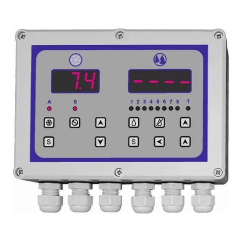
MAKOT MCH-07 v. 2 User manual

Strona 1z 26
PPH MAKOT
ul. Przewóz 34/304
30-716 Kraków | Poland
www.makot.pl
537 872 522 (Sales Department)
602 260 992 (Technical Department)
biuro@makot.pl (Sales Department)
1. DESCRIPTION.
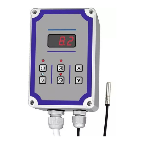
The MCH-07 v. 2 controller is a universal, combined controller intended for use in milking
devices and milk tanks. This controller allows you to cool the milk contained in the tank
and to carry out the milk tanks and milking devices washing process.
The controller is characterized by flexibility in adapting it to various requirements. It is
fully programmable at the installation stage, and at the same time protected against
possible interference by the user in the settings.
The controller consists of two complex segments:
cooling segment,
washing segment,
however, it is not possible, even accidentally, to activate the washing process during
the cooling process. The washing segment is activated only when the cooling is switched
off.
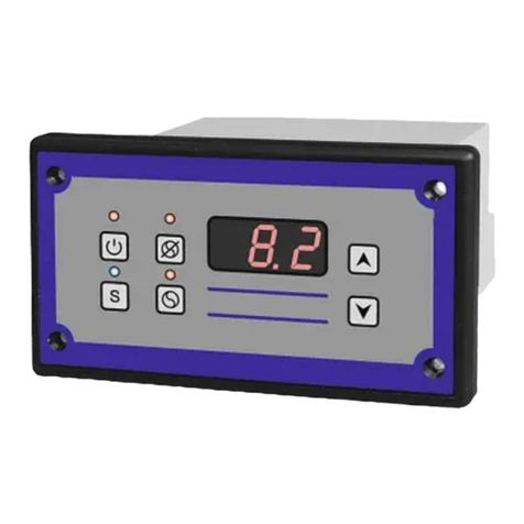
The MCH-07 v. 2 controller has a waterproof casing (protection class IP65), adapted
for built-up. On request there is also a version with a flange for panel mounting (variant
MCH-07.f). Power as well as control inputs and outputs are led through glands placed on
the lower part of the casing, however, on request, a version with glands placed on the
back of the casing is provided, which allows the controller to be installed in such a way
that the wires are hidden (variant MCH-07.b).
In the set with the controller there is a temperature sensor. In version MCH-07T v. 2
an additional temperature sensor is connected, which controls the heating of the water
temperature during the washing process.
The temperature sensors are located in the rubber cover (protection class IP68), ending
with stainless steel sleeve. The controller signals the failure of the temperature sensor.

Strona 2z 26
zasilanie
230V AC 50/60 HZ
stopień ochrony
IP65
znak bezpieczeństwa
CE
2. INSTALLING AND CONNECTING THE CONTROLLER.
In order to install the controller, unscrew the six screws and swivel the front of the
controller, paying attention to the cable connecting the upper PCB board with the
bottom board. After unfolding the casing, disconnect this cable. The cable is
disconnected by removing the connector plug located in the bottom plate.

Strona 3z 26
ATTENTION
Fixing the casing can be done only by screwing using the marked holes. It is forbidden
to drill the housing and fix the casing through such holes, because it causes loss
of tightness of the casing.
MCH-07T version
In the event that the relay no. 4 in the washing segment is set as the stirrer control, then
the control of the stirrer of the cooling segment and the washing segment can be
combined.

Strona 4z 26
Control of 230V AC power via relay no. 5.
3. COOLING SEGMENT.
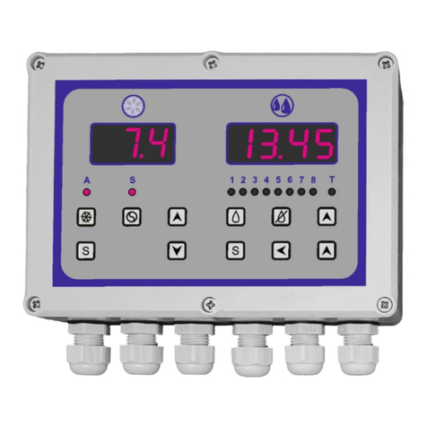
Activation of the cooling process by the user blocks the possibility of switching on the
washing process, which results in the total turning off of the washing segment display.
view of the controller with the cooling process on

Strona 5z 26
3.1. Technical data of the cooling segment.
temperature measuring range
from -40,0 OC to +99,0 OC
control temperature range
from -40,0 OC to +99,0 OC
(decreased by a set hysteresis)
measuring resolution of the temperature measurer
(resolution of control temperature settings)
1 OC in the range below -9,9 OC
0,1 OC in the range between -9,9 OC and +99,0 OC
control hysteresis
[programmable parameter]
from 1,0 OC to 20,0 OC
pre-cooling time
[programmable parameter]
from 1 h to 18 h
cooling delay time
[programmable parameter]
from 1 min. to 99 min.
stirrer working time
[programmable parameter]
from 1 min. to 60 min.
stirrer standstill time
[programmable parameter]
from 1 min. to 60 min.
stirrer manual work time
[programmable parameter]
continuous or from 1 min. to 60 min.
length of temperature sensors
5 m
type of temperature sensor
thermistor NTC
type of temperature meter
digital LED
load capacity of the relay contacts controlling the unit
30A 250V AC
load capacity of the relay contacts controlling the
stirrer
10A 250V AC
3.2. Controller functions in the cooling mode.
The cooling segment of the MCH-07 v. 2 controller is equipped with the functions
described below.
1. Function that allows controlling the operation of the unit according to two set
temperatures, e.g. pre-cooling temperature after milking and the temperature
of the target cooling temperature in the storage process.
2. Function of delaying the activation of the cooling process for the time needed
to finish the milking process.
3. The supervisory function of the unit operation, consisting in the possibility of setting
the maximum and minimum working time of the unit, as well as the minimum time
of standstill of the unit.
4. Function of the possibility of setting the automatic work of the stirrer in two variants:
cyclic work of the stirrer, independent of the operating condition of the unit;
the stirrer works continuously during the operation of the unit, and when
the unit is switched off, the stirrer switches to cyclical operation.
5. Function of manual switching on of the stirrer's work.
6. Function of saving maximum and minimum temperature values throughout
the controller's work cycle; this function is combined with the possibility

Strona 6z 26
of temporally delaying the recording of temperature data to the controller's memory
from the moment of its switching on.
7. Function of saving the maximum temperature value in the washing process.
8. Function of monitoring and signaling of the measuring sensor damage.
3.3. Programming for the cooling segment.
The controller is factory-programmed for standard operating conditions. In order to
change the factory default, enter the settings mode and make the required corrections.
The following figure illustrates the programming procedure:
3.4. Cooling segment operation by the installer.
Entering the settings can be made both when the cooling process is on or off. In the case
of entering the settings the process is on, the cooling will be interrupted and after
extiting from the settings, the cooling should be switched on again.
3.4.1. Table of settings for the cooling segment.
ATTENTION
The parameters from the table below, which are marked in gray, must not be
changed. The warranty granted by the manufacturer does not cover damage to the
controller due to the change of these parameters.

Strona 7z 26
DESCRIPTION
OF THE FUNCTION
SYMBOL
RANGE OF SETTINGS
FACTORY
SETTING
entry in the settings
UC
access code
12.0
limitation of the lower value
for the control temperature
range 1
b1
the possibility of setting the temperature
from -40 OC to +99 OC, every 1,0 OC
2.0 (OC)
limitation of the upper value
for the control temperature
range 1
b2
the possibility of setting the temperature
from -40 OC to +99 OC, every 1,0 OC
10.0 (OC)
control hysteresis
HI
the possibility of setting the temperature
from 1,0 OC to 20 OC, every 0,1 OC
2.0 (OC)
blockade of control
temperature changes
LF
0 –off (blockade inactive)
1 –on (blockade active)
0
delay of turning on cooling for
milking time
0d
0 –off
>0 –on: the possibility of setting the time
from 0 min. to 99 min., every 1 min.
0
milk pre-cooling time
FC
0 –off
>0 –on: the possibility of setting the time
from 0 h to 18 h, every 1 h
0
minimum working time of the
unit
CA
0 –off
>0 –on: the possibility of setting the time
from 0 min. to 60 min., every 1 min.
0
maximum working time of the
unit 2
CC
0 –off
>0 –on: the possibility of setting the time
from 0 h to 9 h, every 1 h
0
minimum standstill time
of the unit
CF
0 –off
>0 –on: the possibility of setting the time
from 0 min. to 60 min., every 1 min.
0
AS
changing the parameter value is not
recommended 3
3.0
AP
3.0
stirrer operating mode
F0
0 –work according to times set in
parameters E1 and E2, independent of the
operation of the unit
1 –continuous work during the unit
operation, and during the standstill of the
unit, the stirrer works according to times
set in parameters E1 and E2
1
standstill time of the stirrer
E1
the possibility of setting the time from 1 min.
to 60 min., every 1 min.
15 (min.)
working time of the stirrer
E2
the possibility of setting the time from 1 min.
to 60 min., every 1 min.
2 (min.)
stirrer manual operation
CP
0 –continuous work
>0 –the possibility of setting the time from 1
min. to 60 min., every 1 min.
5 (min.)
LP
changing the parameter value is not
recommended 3
14.0
EP
40
CL
1
delay in measuring the
maximum and minimum
temperatures after turning on
the cooling process
AA
the possibility of setting the time from 0 h to
18 h, every 1 h
2.0 (h)
return to factory settings
PP
0 –off
0

Strona 8z 26
1 –on
scaling the temperature
sensor 4
CU
the possibility of setting the temperautre
from -10,0 OC to +10,0 OC, every 0,1 OC
0.0
exit from the settings
EE
1Adjustments must be made so that the condition b1<b2 is always met. The values of parameters b1 and b2
they are not control temperature settings; these are the temperature values between which the control
temperature can be set (a section from the entire control temperature range of the controller).
2This function is active only when the minimum standstill time of the unit has been set (CF parameter).
3Changing the parameter value is not recommended, because it can lead to incorrect operation of the
controller, and even its damage.
4Set up during the production phase –do not change without a clear need.
3.4.2. Unit control function.
The unit is controlled in the cooling phase depending on the temperature in the cooling
chamber. The controller allows one or two settings to be controlled, depending on the
FC parameter settings (milk pre-cooling time –see section 3.4.1. Table of settings for the
cooling segment):
FC=0 –no pre-cooling. In this case, the settings made in parameter t1 (see section
3.5. Table of setting for the cooling segment available to the user) are the only
temperature for cooling the milk; the cooling signal diode is permanently on.
FC>0 –during the time set in this parameter, initial cooling takes place according to
the settings made in parameter t1; during the initial cooling the cooling signal diode
blinks. After the time set in the FC parameter has elapsed, the transition takes place
for cooling according to the temperature set in parameter t2; the cooling signal
diode is permanently on.
At any time, you can interrupt the initial cooling and go for cooling according to the
target temperature. This is done by pressing the button during pre-cooling;
the signal diode starts to changes its lighting to continuous.
The controller can control the cooling temperature in the range from -40 OC to +98 OC.
In order to limit the scope of the control so as to prevent the user of the cooling device
from setting the temperature outside this range, set the appropriate parameters in the
appropriate ranges: b1 –limiting the lower value for the control temperature range and
b2 –limiting the upper value for the control temperature range.
It is also important to set the control hysteresis correctly –parameter HI. The control
hysteresis determines the temperature difference at which the compressor is switched
off and then on, e.g. if the control temperature is set as 4OC, and the hysteresis on 2OC,
the compressor will stop after reaching 4OC, and its re-activation will occur after
the temperature increases to 4 + 2 = 6OC.
The controller allows setting the control hysteresis in the range from 1OC to 20OC.

Strona 9z 26
ATTENTION
The set hysteresis value automatically limits the extreme values of the control range
so that the operating range of the controller is not exceeded.
3.4.3. Delaying the activation of the cooling process.
This function makes it possible to switch on the controller by pressing the button
and the cooling process will be delayed. This delay will be equal to the set time
in parameter 0d (default 0d=0). This solution enables simultaneous activation of the
controller's operation with the start of the milking process.
If this function has been activated, after pressing the button , the display will show the
time to start the cooling process. This signaling, in order to more accurately distinguish
the displayed time, is additionally underlined by blinking alternately dots
at the display.
At any time, by pressing the button again you can interrupt the countdown of time,
and thus go to the cooling process.
3.4.4. The supervisory of the unit operation.
The controller is equipped with compressor safety functions, such as:
CF –minimum standstill time of the unit,
CA –minimum operating time of the unit,
CC –maximum working time of the unit.
Setting of these parameters can also affecton actual temperature fluctuations in the
cooling chamber. For example, if the compressor has a minimum operating time
of 5 minutes and the control temperature has been reached after 3 minutes,
the compressor will not be switched off earlier than after 5 minutes. The same applies
to the minimum standstill time of the unit. In this case, the temperature fluctuations
in the cooling chamber will be higher than it would appear from the set hysteresis
(parameter HI).
3.4.5. Automatic work of the stirrer.
Automatic stirrer operation can take place in two variants, depending on the settings
made:
F0=0 –cyclical operation of the stirrer, independent of the operation of the unit,
F0=1 –continuous operation of the stirrer during operation of the unit and cyclic
operation during the unit standstill.
The cyclic work of the stirrer takes place as follows: work –standstill –work –..., always
starting from work.
The working time of the stirrer is determined by parameter E1, and its standstill time is
determined by parameter E2.

Strona 10 z 26
3.4.6. Manual work of the stirrer.
In addition to the automatic work of the stirrer, the controller allows you to manually
switch on the stirrer at any time (when the stirrer is not working). Depending on the
settings made in the CP parameter, you can set two variants of manual work:
CP=0 –continuous stirrer operation from the moment of manual activation until
the manual switch-off,
CP>0 –work for a specified period of time; the value of the CP parameter (>0) means
the working time of the stirrer activated manually; the stirrer operation in this
variant can also be interrupted at any time by pressing the button .
3.4.7. Saving the maximum and minimum temperature values during the cooling
process.
The controller has a function of saving in its internal memory maximum and minimum
temperature values that occur throughout the controller's entire cycle. This function
makes it possible to check whether the contents of the tank are stored
in correct temperature conditions.
At the moment the cooling is switched on, after the programmed delay has elapsed
(parameter AA –see section 3.4.1. Table of settings for the cooling segment),
the minimum and maximum temperature values are saved in the controller memory.
The programmable delay time of enabling this function allows the fresh milk to be pre-
cooled and thus does not take into account the maximum temperature when the cooling
is started. The factory setting is 2 hours, however, this time should be selected according
to the actual operating conditions of the controller.
At any time, you can read the currently available maximum and minimum values. This is
done by briefly pressing the Sbutton and selecting the parameter H0 (maximum value)
or parameter L0 (minimum value).
ATTENTION
In the absence of entries of maximum and minimum temperature values in the
controller's memory the symbol --- appears on the display.
Clearing the memory of maximum and minimum temperature values is caused:
automatically after turning the cooling off and on again; switching off the cooling
itself does not erase the memory, it takes place only after switching it on again,
in the event of a power failure.
3.4.8. Saving the maximum temperature value during the washing process.
The maximum temperature that is present when the controller is not in cooling mode is
also written to the controller's internal memory. Because the washing process must be
carried out with the cooling off, the temperature then present is also the maximum
temperature in the washing process. However, if the washing process is not carried out

Strona 11 z 26
during inactive cooling, the stored temperature is the maximum value that occurred
at that time.
The deletion of data contained in the memory occurs automatically after starting the
cooling process. In the absence of data saved in the controller's memory after setting
the data reading parameter –HC, the display shows the symbol ---.
3.4.9. Monitoring and signaling of the measuring temperature sensor damage.
If the controller detects damage to the temperature sensor, the unit and the stirrer are
switched off. The letters ACU appear on the display.
ATTENTION
Sensor damage indication also occurs if the temperature range measured by the
controller is exceeded.
3.4.10. Returning to the factory settings.
If changes are made to the factory settings and the controller is not working properly
(at any stage of its use), first you need to resore the factory settings.
In order to do so: enter the settings select the parameter PP confirm set
parameter PP=1 confirm switch off the controller supply voltage switch on the
controller supply voltage again.
After performing the above-described activities, the controller will return to the factory
settings, therefore any changes made to the settings will be deleted.
After switching on the power again, the PP parameter will automatically set to 0.
3.4.11. Scaling the temperature sensor.
If there is a discrepancy in the controller’s temperature meter with the reference meter,
you can adjust the indications.
In order to do so: enter the settings select the CU parameter confirm; the display
will show 0.0 measure the milk temperature with the reference meter the
difference between the reference meter and the controller meter should be set with the
▲and ▼buttons, paying attention whether the value should be added or subtracted
(minus sign) confirm the change by pressing the button Sexit the settings.
ATTENTION
The change of the meter scaling should be done with caution, as in some cases it is
enough to move the measurement sensor to a different location or increase the
contact between the sensor and the measured medium. Particular attention should
be paid to all intermediate measurements, e.g. when measuring milk temperature by
measuring the tank wall temperature.

Strona 12 z 26
3.5. Table of settings for the cooling segment available for the direct user.
ATTENTION
The controller is equipped with a function that makes it impossible to change
the control temperature set by the installer. This function is activated by setting
parameter LF=1 (default LF=0).
DESCRIPTION OF THE FUNCTION
SYMBOL
FACTORY
SETTING
basic control temperature
t1
5.0
pre-cooling temperature
(the function is active at the FC>0 setting (see section 3.4.1. Table of settings
for the cooling segment)
t2
5.0
recalling from the controller memory the maximum temperature value
during the cooling process
H0
-
recalling from the controller memory the minimum temperature value
during the cooling process
L0
-
recalling from the controller memory the maximum temperature value
during the washing process
HC
-
exit the settings
EE
The following figure illustrates the procedure for handling the controller cooling segment
by a direct user.

Strona 13 z 26
3.6. Description of the cooling segment operation.
When the controller is connected to the main, the display shows the currently measured
temperature. In addition to displaying the temperature value, the controller does not
control any external elements.
Pressing the button causes the cooling control operation to start. This status is
indicated by diode placed above the display (blue). Depending on the programming
of the controller, this signaling is intermittently flashing (pre-cooling) or continuous.
The work of the unit is signaled by the diode located above the button. The unit then
works in an automatic cycle according to the settings made. The operation of the stirrer
is indicated by the diode located above the button .
Pressing the button causes manual operation of the stirrer, which is indicated by the
intermittent lighting of the diode located above this button.
Manual operation of the stirrer is possible in the following cases:
if cooling is switched on and the stirrer is not working,
if cooling is switched off,
if the washing process is on.
During the manual release of the stirrer, pressing the button again switches off the
manual working mode.
It is recommended to change the control temperature after switching off the cooling
process.
The temperature values saved can be read both when the cooling process is switched on
and off.

Strona 14 z 26
ATTENTION
Disconnecting the controller from the power supply erases the data contained in its
memory.
4. WASHING SEGMENT.
The washing segment in the MCH-07 v. 2 controller is activated only when cooling is
switched off; this activation is indicated by the appearance of the ----symbol on the
display.
The washing segment may vary depending on the version of the controller:
MCH-07 v. 2 –basic version,
MCH-07T v. 2 –aversion with the possibility of controlling water heating.
view of the controller with the washing process on

Strona 15 z 26
The controller has:
7 relay control outputs; relays with numbers 1, 2, 3, 4, 6, 7 have normally open
contacts that output L 230V AC signal, while relay no. 5 has contacts: input signal,
normally closed contact and normally open contact.
hydrostat connection input (hydrostat activation signal –L 230V),
input for connecting the temperature sensor (only version MCH-07T v.2).
4.1. Technical data of the washing segment.
number of programs
8
number of factory (default) programs
4
maximum number of steps in each program
50
minimum duration of one step
1 s.
maximum duration of one step
99 min.
range of the control temperature
[only MCH-07T v.2 version]
from 9,0 OC to 99,0 OC
resolution of control temperature settings
[only MCH-07T v.2 version]
0,5 OC
length of temperature sensor
[only MCH-07T v.2 version]
5 m
number of relay outputs
7
load capacity of the relay contacts
10A 250V AC
number of control inputs:
hydrostatic (MCH-07 v. 2),
hydrostatic and temperature sensor (MCH-07T v. 2)
1
2
type of display
LED
power supply
23 V AC 50Hz
4.2. Controller functions in washing mode.
The MCH-07 v. 2 controller has a number of functions of the washing segment described
below.

Strona 16 z 26
4.2.1. Washing programs.
Controller’s memory has capacity for 8 programs, with two programs for washing
the milking devices and two programs for washing the cooling devices pre-programmed.
The remaining 4 spots allow an installer to create programs adapted to the individual
needs of an user.
4.2.2. Modification and creation of programs.
The controller allows to modify factory programs according to the needs of the user.
It is also possible to create programs yourself (by the installer). Each program can have
a maximum of 50 steps with a duration of 1 sec. to 99 min. The programming method is
very simple and intuitive –it has been included in the graphic form in section 4.3.2.
Programming for the washing segment.
4.2.3. Protection in the event of a power failure.
Loss of power supply interrupts the execution of the activated washing program. When
the correct supply voltage returns, the program will start in the same place where it was
stopped. In the settings of this function (UAP parameter –see section 4.3.1. Table of
settings for the washing segment), it is possible to temporarily limit the possibility
of returning to the interrupted controller (in range from 1 h to 9 h).
4.2.4. Test mode.
This function allows moving successively to the next program steps without waiting for
the duration of the step to expire. The transition is made by pressing the appropriate
button. This function is only available to the installer.
4.2.5. Return to the factory settings.
In the event of making a mistake while setting the controller's work or finding an
incorrect operation of the controller (at any stage of its use), it is possible to return to
the factory settings (Pd0d parameter –see section 4.3.1. Table of settings for the
washing segment).
4.2.6. Manual activation of the vacuum pump or the stirrer.
The controller is equipped with a button enabling manual activation of the vacuum pump
or the stirrer, regardless of the button , but depending from UPP parameter setting –
see section 4.3.1. Table of settings for the washing segment.
4.2.7. Program start function.
The program is started by manually pressing the button located on the front of the
controller.

Strona 17 z 26
4.2.8. Pausing the program.
The controller allows to pause (hold) the program execution during its duration. This
function allows you to interrupt the program at any time and resume it, which happens
exactly in the same place, in which the program was paused.
4.2.9. Disabling the program.
The controller is equipped with a button that disables the program at any time, without
the possibility of resuming it at the switch-off point. Restarting the program will cause
launching the program from the very beginning.
4.2.10. Displaying the time remaining.
During the program execution, the controller displays the time remaining until the end
of the program.
ATTENTION
The time indicated on the display does not take into account the time of pouring
water.
4.2.11. The function of dependence on the completion of pouring water from the
hydrostatic signal.
The controller allows to program the end of the water dispensing proces from obtaining
a signal from a hydrostatic. This function is secured by setting the maximum time for
pouring water in the event of mechanical suspension of the hydrostatic.
4.2.12. Water heating control (only MCH-07T v. 2 version).
The MCH-07T v. 2 version has a built-in temperature regulator that allows you to control
the heating of water. This function requires the connection of a temperature sensor and
the setting of the temperature of the water heating –the factory setting is 45OC).
4.3. Washing segment use by the installer.
The controller is factory-programmed for standard operating conditions for the purpose
of washing: milk cooler (2 programs) and milking devices (2 programs). Nevertheless,
to ensure proper operation of the controller under specific conditions, appropriate
adjustments of the operating parameters can be made, including the selection of the
appropriate program. Deafault washing programs can be edited according to the user's
needs or you can create your own program.
After the controller has been installed, the correct operation of the entire washing
system can also be checked in an accelerated mode using the test mode.

Strona 18 z 26
4.3.1. Table of settings for the washing segment.
DESCRIPTION OF THE
FUNCTION
SYMBOL
RANGE OF SETTING
FACTORY
SETTING
entry in the settings
U000
access code
121
editing the programs
EdPr
the ability to edit factory programs
and create your own programs –
see section 4.3.2. Programming
for the washing segment
8 programs –
see section 4.3.3.
Factory programs
for washing
segment
setting the number of program
to be executed by the
controller
dPro
Pro1, Pro2, Pro3, Pro4, Pro 5,
Pro6, Pro7, Pro8
Pro1
setting the manual activation of
the vacuum pump or the stirrer
UPP
0 –off
1 –manual activation of the
vacuum pump
2 –manual activation of the stirrer
0
test mode
UEL
0 –off
1 –on; controller works in the test
mode
0
setting the heating option
[only MCH-07T v.2 version]
OHA
0 –off
1 –heating with active maximum
time
2 –heating without active
maximum time
2
setting the maximum loss
of power time, after which
the controller will return to the
interrupted operation
UAP
0 –off; resuming operation is not
time-limited
1 –the possibility of setting the
time from 1 h to 9 h; if the break is
longer, the controller will not
resume its operation
9 (h)
return to the factory settings
powrót do ustawień
fabrycznych przy następnym
uruchomieniu sterownika
Pd0d
0 –off
1 –on; return to the factory
settings, next time the controller is
started
0
exit from the settings
EE
4.3.2. Programming for the washing segment.
The controller is protected against accidental entry into the service settings mode,
assuming only those available to the installer or service technician. These safeguards
include:
the necessity o press and hold the Sbutton (enter settings) for approx. 15 sec.,
the necessity to enter the access code (see section 4.3.1. Table of settings for the
washing segment),
entering the access code in a few steps.
ATTENTION
Please do not share the access code with the direct users.

Strona 19 z 26
All changes in programming are made with the washing process switched off and at the
same time active washing segment (cooling is off).
4.3.2.1. Entering the settings.
The procedure for entering the access code to enter the settings and programming is
shown below –as graphics.
4.3.2.2. Selecting the function to be edited.
In section 4.3.1. Table of settings for the washing segment all available functions are
given with their description and possible values to be set. If you want to change any
parameter from the available settings, enter the settings (see section 4.3.2.1.), and then
select the specific function that will be changed.
The following is a graphical representation of the change in the factory setting of the
washing program number (program number 1 is preset).

Strona 20 z 26
4.3.2.3. Editing the programs.
The controller is equipped with: 4 washing programs (pre-programmed), which can be
freely edited by the installer as required, as well as 4 washing programs to be
programmed by the installer (they are empty as default). Each program can contain up
to 50 steps. Each step is assigned:
status of all 7 relay outputs,
hydrostatic input status,
duration of the step.
When programming or editing an existing program, the following buttons perform the
following functions:
–changing the value of a setting upwards, e.g. function, time,
temperature,
–relay activation
–changing the value of a setting downwards, e.g. function, time,
temperature
–relay deactivation
–moving left
–confirmation of entering the parameter
–confirmation of changes made
–exit from the settings after confirming the changes with the S button
–exit from the settings without making changes
This manual suits for next models
1
Other MAKOT Controllers manuals
Popular Controllers manuals by other brands
Speck pumpen
Speck pumpen BADU Logic 1 Installation and operating instructions
SMC Networks
SMC Networks ITV1000-52 Series Operator's manual
fakro
fakro ZWK1 user manual
AJAX Systems
AJAX Systems SpaceControl user manual
Crouzet
Crouzet MILLENIUM II+ Series installation manual
LAE electronic
LAE electronic AT1-5 user manual
